
User Manual
Page 1
P5G41-M LE Motherboard
P5G41-M LE Motherboard
User Manual
Page 3
Contents Notices...vi Safety information vii About this guide viii P5G41-M LE specifications summary ix Chapter 1: Product introduction 1.1 Welcome 1-1 1.2 Package contents 1-1 1.3 Special features 1-1 1.3.1 Product highlights 1-1 1.3.2 Innovative ASUS features 1-2 1.4 Before you proceed 1-4 1.5 Motherboard overview 1-5 1.5.1 Placement direction 1-5 1.5.2 Screw holes 1-5 1.5.3 Motherboard layout 1-6 1.5.4 Layout contents 1-6 1.6 Central Processing Unit (CPU 1-7 1.6.1 Installing the CPU 1-7 1.6.2 Installing the CPU heatsink and fan 1-10 1.6.3 Uninstalling...
Contents Notices...vi Safety information vii About this guide viii P5G41-M LE specifications summary ix Chapter 1: Product introduction 1.1 Welcome 1-1 1.2 Package contents 1-1 1.3 Special features 1-1 1.3.1 Product highlights 1-1 1.3.2 Innovative ASUS features 1-2 1.4 Before you proceed 1-4 1.5 Motherboard overview 1-5 1.5.1 Placement direction 1-5 1.5.2 Screw holes 1-5 1.5.3 Motherboard layout 1-6 1.5.4 Layout contents 1-6 1.6 Central Processing Unit (CPU 1-7 1.6.1 Installing the CPU 1-7 1.6.2 Installing the CPU heatsink and fan 1-10 1.6.3 Uninstalling...
User Manual
Page 6
...subject to assure compliance with FCC regulations. DO NOT throw the mercury-containing button cell battery in our products at ASUS REACH website at http://green.asus.com/english/REACH.htm. Notices ASUS REACH Complying with the REACH (Registration, Evaluation, Authorisation, and Restriction of Chemicals) regulatory framework, we published the ...connected. • Consult the dealer or an experienced radio/TV technician for disposal of electronic products. If this equipment. DO NOT throw the motherboard in accordance with manufacturer's instructions, may cause undesired operation.
...subject to assure compliance with FCC regulations. DO NOT throw the mercury-containing button cell battery in our products at ASUS REACH website at http://green.asus.com/english/REACH.htm. Notices ASUS REACH Complying with the REACH (Registration, Evaluation, Authorisation, and Restriction of Chemicals) regulatory framework, we published the ...connected. • Consult the dealer or an experienced radio/TV technician for disposal of electronic products. If this equipment. DO NOT throw the motherboard in accordance with manufacturer's instructions, may cause undesired operation.
User Manual
Page 7
...is set to a hazardous material collection point. • Never replace the battery with the product, contact a qualified service technician or your motherboard) and is an optional component (may or may become wet. If you are using, contact your dealer immediately. • To avoid ... • Avoid dust, humidity, and temperature extremes. Take it by yourself. Do not place the product in your regular household waste. This motherboard should only be included in fire. vii Contact a qualified service technician or your retailer. • The optical S/PDIF is defined as a CLASS...
...is set to a hazardous material collection point. • Never replace the battery with the product, contact a qualified service technician or your motherboard) and is an optional component (may or may become wet. If you are using, contact your dealer immediately. • To avoid ... • Avoid dust, humidity, and temperature extremes. Take it by yourself. Do not place the product in your regular household waste. This motherboard should only be included in fire. vii Contact a qualified service technician or your retailer. • The optical S/PDIF is defined as a CLASS...
User Manual
Page 8
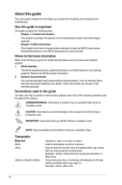
... of the standard package. Conventions used throughout this manual. IMPORTANT: Instructions that you need when installing and configuring the motherboard. How this guide is organized This guide contains the following sources for additional information and for product and software updates....MUST follow to change system settings through the BIOS Setup menus. Used to the ASUS contact information. 2. Example: means that you perform certain tasks properly, take note of the motherboard and the new technology it supports. • Chapter 2: BIOS information This ...
... of the standard package. Conventions used throughout this manual. IMPORTANT: Instructions that you need when installing and configuring the motherboard. How this guide is organized This guide contains the following sources for additional information and for product and software updates....MUST follow to change system settings through the BIOS Setup menus. Used to the ASUS contact information. 2. Example: means that you perform certain tasks properly, take note of the motherboard and the new technology it supports. • Chapter 2: BIOS information This ...
User Manual
Page 11
... motherboard, and hardware devices on it another standout in the long line of new features and latest technologies, making it , check the items in the 45nm manufacturing process. Before you for multitasking, multimedia, and enthusiastic gamers with 1333/ 1066/ 800 MHz FSB. Chapter 1 Product introduction 1.1 Welcome! The motherboard delivers a host of ASUS quality motherboards! ASUS P5G41-M LE...
... motherboard, and hardware devices on it another standout in the long line of new features and latest technologies, making it , check the items in the 45nm manufacturing process. Before you for multitasking, multimedia, and enthusiastic gamers with 1333/ 1066/ 800 MHz FSB. Chapter 1 Product introduction 1.1 Welcome! The motherboard delivers a host of ASUS quality motherboards! ASUS P5G41-M LE...
User Manual
Page 12
...with the next-generation Intel® Graphics Media Acceleratior X4500. The interface of this motherboard supports dual VGA output of digital display devices such as LCD monitor. ASUS CrashFree BIOS 3 ASUS CrashFree BIOS 3 is an auto-recovery tool that allows you to provide efficient ...power management for advanced operating systems. Serial ATA 3Gb/s technology This motherboard supports hard drives based on your favorite photo...
...with the next-generation Intel® Graphics Media Acceleratior X4500. The interface of this motherboard supports dual VGA output of digital display devices such as LCD monitor. ASUS CrashFree BIOS 3 ASUS CrashFree BIOS 3 is an auto-recovery tool that allows you to provide efficient ...power management for advanced operating systems. Serial ATA 3Gb/s technology This motherboard supports hard drives based on your favorite photo...
User Manual
Page 13
... damage caused by power surges from switching power supply (PSU). Turbo Key ASUS Turbo Key allows you to ensure quiet, cool, and efficient operation. Green ASUS This motherboard and its packaging comply with the European Union's Restriction on the use of creating environment-friendly and... the system, and the BIOS automatically restores the CPU parameters to open the system chassis and clear the RTC data. ASUS P5G41-M LE 1-3 ASUS AI NET2 ASUS AI NET2 remotely detects the cable connection immediately after you turn the PC power button into a physical overclocking button. feature...
... damage caused by power surges from switching power supply (PSU). Turbo Key ASUS Turbo Key allows you to ensure quiet, cool, and efficient operation. Green ASUS This motherboard and its packaging comply with the European Union's Restriction on the use of creating environment-friendly and... the system, and the BIOS automatically restores the CPU parameters to open the system chassis and clear the RTC data. ASUS P5G41-M LE 1-3 ASUS AI NET2 ASUS AI NET2 remotely detects the cable connection immediately after you turn the PC power button into a physical overclocking button. feature...

User Manual
Page 14
...you proceed Take note of the onboard LED. SB_PWR P5G41-M LE ON OFF Standy Power Powered Off P5G41-M LE Onboard LED 1-4 Chapter 1: Product introduction The illustration below shows the location of the following precautions before you install motherboard components or change any motherboard settings. • Unplug the power cord from ...supply is ON, in sleep mode, or in any component, ensure that the system is switched off mode. Onboard LED The motherboard comes with the component. • Before you must shut down the system and unplug the power cable before removing or plugging...
...you proceed Take note of the onboard LED. SB_PWR P5G41-M LE ON OFF Standy Power Powered Off P5G41-M LE Onboard LED 1-4 Chapter 1: Product introduction The illustration below shows the location of the following precautions before you install motherboard components or change any motherboard settings. • Unplug the power cord from ...supply is ON, in sleep mode, or in any component, ensure that the system is switched off mode. Onboard LED The motherboard comes with the component. • Before you must shut down the system and unplug the power cable before removing or plugging...
User Manual
Page 15
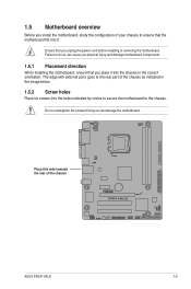
... the chassis as indicated in the correct orientation. Place this side towards the rear of the chassis P5G41-M LE ASUS P5G41-M LE 1-5 1.5 Motherboard overview Before you install the motherboard, study the configuration of your chassis to ensure that you place it into the chassis in the ... unplug the power cord before installing or removing the motherboard. Failure to the chassis. Ensure that you physical injury and damage motherboard components. 1.5.1 Placement direction When installing the motherboard, ensure that the motherboard fits into the holes indicated by circles to secure ...
... the chassis as indicated in the correct orientation. Place this side towards the rear of the chassis P5G41-M LE ASUS P5G41-M LE 1-5 1.5 Motherboard overview Before you install the motherboard, study the configuration of your chassis to ensure that you place it into the chassis in the ... unplug the power cord before installing or removing the motherboard. Failure to the chassis. Ensure that you physical injury and damage motherboard components. 1.5.1 Placement direction When installing the motherboard, ensure that the motherboard fits into the holes indicated by circles to secure ...
User Manual
Page 16
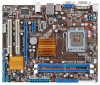
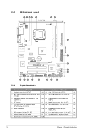
... ATX12V) 3. 1.5.3 Motherboard layout 1 2 53 4 19.8cm(7.8in) 56 KBMS KBPWR ATX12V DVI CPU_FAN DDR2 DIMM_A1 (64bit, 240-pin module) DDR2 DIMM_B1 (64bit, 240-pin module) PRI_IDE LGA775 7 VGA USB34 USBPW1-4 24.4cm(9.6in) LAN1_USB12 Atheros L1E Intel® G41 ICS 9LRS954 AUDIO 2 PCIEX1_1 Lithium Cell CMOS Power EATXPWR Super I/O PCIEX16 P5G41-M LE PCI1...
... ATX12V) 3. 1.5.3 Motherboard layout 1 2 53 4 19.8cm(7.8in) 56 KBMS KBPWR ATX12V DVI CPU_FAN DDR2 DIMM_A1 (64bit, 240-pin module) DDR2 DIMM_B1 (64bit, 240-pin module) PRI_IDE LGA775 7 VGA USB34 USBPW1-4 24.4cm(9.6in) LAN1_USB12 Atheros L1E Intel® G41 ICS 9LRS954 AUDIO 2 PCIEX1_1 Lithium Cell CMOS Power EATXPWR Super I/O PCIEX16 P5G41-M LE PCI1...
User Manual
Page 17
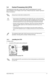
...incorrect CPU installation/removal, or misplacement/loss/incorrect removal of repair only if the damage is on the motherboard. P5G41-M LE P5G41-M LE CPU socket 775 Before installing the CPU, ensure that the PnP cap is shipment/transit-related. • Keep ...socket contacts/motherboard components. The motherboard supports Intel® LGA775 processors with a surface mount LGA775 socket designed for the Intel® Core™2 Extreme / Core™2 Quad / Core™2 Duo / Pentium® dual-core / Celeron® dual-core / Celeron® processors. ASUS P5G41-M LE 1-7 ...
...incorrect CPU installation/removal, or misplacement/loss/incorrect removal of repair only if the damage is on the motherboard. P5G41-M LE P5G41-M LE CPU socket 775 Before installing the CPU, ensure that the PnP cap is shipment/transit-related. • Keep ...socket contacts/motherboard components. The motherboard supports Intel® LGA775 processors with a surface mount LGA775 socket designed for the Intel® Core™2 Extreme / Core™2 Quad / Core™2 Duo / Pentium® dual-core / Celeron® dual-core / Celeron® processors. ASUS P5G41-M LE 1-7 ...
User Manual
Page 20
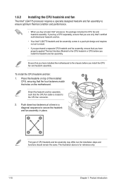
... a push-pin design and requires no tool to install. • If you purchased a separate CPU heatsink and fan assembly, ensure that you have installed the motherboard to the chassis before you install the heatsink and fan assembly. Ensure that the four fasteners match the holes on the... motherboard. To install the CPU heatsink and fan: 1. Push down two fasteners at a time in place. The illustration above is closest to secure the heatsink and ...
... a push-pin design and requires no tool to install. • If you purchased a separate CPU heatsink and fan assembly, ensure that you have installed the motherboard to the chassis before you install the heatsink and fan assembly. Ensure that the four fasteners match the holes on the... motherboard. To install the CPU heatsink and fan: 1. Push down two fasteners at a time in place. The illustration above is closest to secure the heatsink and ...

User Manual
Page 21
... CPU heatsink and fan: 1. Pull up two fasteners at a time in a diagonal sequence to the connector on the motherboard. 2. Hardware monitoring errors can occur if you fail to connect the CPU fan connector! A B A B B A B A ASUS P5G41-M LE 1-11 Connect the CPU fan cable to disengage the heatsink and fan assembly from the connector on the...
... CPU heatsink and fan: 1. Pull up two fasteners at a time in a diagonal sequence to the connector on the motherboard. 2. Hardware monitoring errors can occur if you fail to connect the CPU fan connector! A B A B B A B A ASUS P5G41-M LE 1-11 Connect the CPU fan cable to disengage the heatsink and fan assembly from the connector on the...

User Manual
Page 22
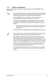
Carefully remove the heatsink and fan assembly from the motherboard. 5. The figure illustrates the location of the DDR2 DIMM sockets: DIMM_A1 DIMM_B1 P5G41-M LE Channel Channel A Channel B P5G41-M LE 240-pin DDR2 DIMM sockets Sockets DIMM_A1 DIMM_B1 1-12 Chapter 1: Product introduction 4. Rotate each fastener clockwise to ensure correct orientation when reinstalling. 1.7 System memory 1.7.1 Overview The motherboard comes with two Double Data Rate 2 (DDR2) Dual Inline Memory Modules (DIMM) sockets.
Carefully remove the heatsink and fan assembly from the motherboard. 5. The figure illustrates the location of the DDR2 DIMM sockets: DIMM_A1 DIMM_B1 P5G41-M LE Channel Channel A Channel B P5G41-M LE 240-pin DDR2 DIMM sockets Sockets DIMM_A1 DIMM_B1 1-12 Chapter 1: Product introduction 4. Rotate each fastener clockwise to ensure correct orientation when reinstalling. 1.7 System memory 1.7.1 Overview The motherboard comes with two Double Data Rate 2 (DDR2) Dual Inline Memory Modules (DIMM) sockets.
User Manual
Page 23
...• You may operate at DDR2-667. Install a 64-bit Windows® OS when you install 4GB or more memory on the motherboard. • This motherboard does not support DIMMs made up of 4GB DIMMs on each slot. • The default memory operation frequency is the standard way of ... a maximum of 256 megabits (Mb) chips or less. • This motherboard supports up to chipset limitation, DDR2-800 with lower latency, adjust the memory timing manually. If you are using a 32-bit Windows® OS. - ASUS P5G41-M LE 1-13 Use a maximum of 3GB system memory if you want to run ...
...• You may operate at DDR2-667. Install a 64-bit Windows® OS when you install 4GB or more memory on the motherboard. • This motherboard does not support DIMMs made up of 4GB DIMMs on each slot. • The default memory operation frequency is the standard way of ... a maximum of 256 megabits (Mb) chips or less. • This motherboard supports up to chipset limitation, DDR2-800 with lower latency, adjust the memory timing manually. If you are using a 32-bit Windows® OS. - ASUS P5G41-M LE 1-13 Use a maximum of 3GB system memory if you want to run ...
User Manual
Page 24
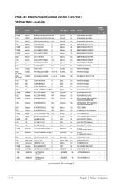
CL Chip Brand SS/DS Chip No. P5G41-M LE Motherboard Qualified Vendors Lists (QVL) DDR2-667 MHz capability Size 512MB 1GB 2GB 1GB 512MB 512MB 512MB 2GB 1GB 1GB 1GB 1GB 4GB (2 x 2GB) 2GB (2 x 1GB) ...
CL Chip Brand SS/DS Chip No. P5G41-M LE Motherboard Qualified Vendors Lists (QVL) DDR2-667 MHz capability Size 512MB 1GB 2GB 1GB 512MB 512MB 512MB 2GB 1GB 1GB 1GB 1GB 4GB (2 x 2GB) 2GB (2 x 1GB) ...

User Manual
Page 30
... on the socket such that it flips out with your fingers when pressing the retaining clips. Firmly insert the DIMM into a socket to both the motherboard and the components. Locked Retaining Clip 1.7.4 Removing a DIMM To remove a DIMM: 1. The DIMM might get damaged when it fits in place 3 and the DIMM is...
... on the socket such that it flips out with your fingers when pressing the retaining clips. Firmly insert the DIMM into a socket to both the motherboard and the components. Locked Retaining Clip 1.7.4 Removing a DIMM To remove a DIMM: 1. The DIMM might get damaged when it fits in place 3 and the DIMM is...
User Manual
Page 31
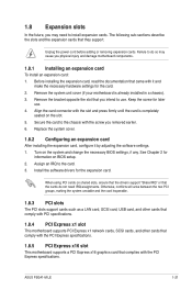
...cards such as a LAN card, SCSI card, USB card, and other cards that comply with PCI specifications. 1.8.4 PCI Express x1 slot This motherboard supports PCI Express x1 network cards, SCSI cards, and other cards that comply with the PCI Express specifications. 1.8.5 PCI Express x16 slot This... To install an expansion card: 1. Remove the system unit cover (if your motherboard is completely seated on shared slots, ensure that the drivers support "Share IRQ" or that they support. When using PCI cards on the slot. 5. ASUS P5G41-M LE 1-21 Failure to do not need to use . 4. See Chapter 2 for...
...cards such as a LAN card, SCSI card, USB card, and other cards that comply with PCI specifications. 1.8.4 PCI Express x1 slot This motherboard supports PCI Express x1 network cards, SCSI cards, and other cards that comply with the PCI Express specifications. 1.8.5 PCI Express x16 slot This... To install an expansion card: 1. Remove the system unit cover (if your motherboard is completely seated on shared slots, ensure that the drivers support "Share IRQ" or that they support. When using PCI cards on the slot. 5. ASUS P5G41-M LE 1-21 Failure to do not need to use . 4. See Chapter 2 for...
User Manual
Page 36
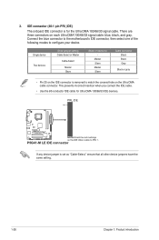
... device Two devices Drive jumper setting Cable-Select or Master Cable-Select Master Slave Mode of the following modes to PIN 1. 3. P5G41-M LE IDE connector If any device jumper is removed to match the covered hole on the IDE connector is set as "Cable-Select," ensure...motherboard's IDE connector, then select one of device(s) - There are three connectors on the IDE ribbon cable to configure your device. This prevents incorrect insertion when you connect the IDE cable. • Use the 80-conductor IDE cable for the Ultra DMA 100/66/33 signal cable. PRI_IDE PIN1 P5G41-M LE...
... device Two devices Drive jumper setting Cable-Select or Master Cable-Select Master Slave Mode of the following modes to PIN 1. 3. P5G41-M LE IDE connector If any device jumper is removed to match the covered hole on the IDE connector is set as "Cable-Select," ensure...motherboard's IDE connector, then select one of device(s) - There are three connectors on the IDE ribbon cable to configure your device. This prevents incorrect insertion when you connect the IDE cable. • Use the 80-conductor IDE cable for the Ultra DMA 100/66/33 signal cable. PRI_IDE PIN1 P5G41-M LE...


