
Motherboard Installation Guide
Page 1
Motherboard P5E64 WS Evolution
Motherboard P5E64 WS Evolution

Motherboard Installation Guide
Page 3
... Notices...viii Safety information ix About this guide x P5E64 WS Evolution specifications xii Chapter 1: Product introduction 1.1 Welcome 1-1 1.2 Package contents 1-1 1.3 Special features 1-2 1.3.1 Product highlights 1-2 1.3.2 ASUS special features 1-4 1.3.3 ASUS stylish features 1-7 1.3.4 ASUS intelligent overclocking features 1-7 Chapter 2: Hardware information 2.1 Before you proceed 2-1 2.2 Motherboard overview 2-2 2.2.1 Placement direction 2-2 2.2.2 Screw holes 2-2 2.2.3 Motherboard layout 2-3 2.2.4 Layout contents 2-4 2.3 Central Processing Unit (CPU 2-6 2.3.1 Installing...
... Notices...viii Safety information ix About this guide x P5E64 WS Evolution specifications xii Chapter 1: Product introduction 1.1 Welcome 1-1 1.2 Package contents 1-1 1.3 Special features 1-2 1.3.1 Product highlights 1-2 1.3.2 ASUS special features 1-4 1.3.3 ASUS stylish features 1-7 1.3.4 ASUS intelligent overclocking features 1-7 Chapter 2: Hardware information 2.1 Before you proceed 2-1 2.2 Motherboard overview 2-2 2.2.1 Placement direction 2-2 2.2.2 Screw holes 2-2 2.2.3 Motherboard layout 2-3 2.2.4 Layout contents 2-4 2.3 Central Processing Unit (CPU 2-6 2.3.1 Installing...

Motherboard Installation Guide
Page 17
... in the long line of the above items is damaged or missing, contact your motherboard package for the following items. Motherboard I/O modules Cables Accessories Application DVD Documentation ASUS P5E64 WS Evolution 1 x 2��-p�o��rt�U��S�B 1 p�...Serial ATA signal cable for 8 devices Serial ATA power cable for buying an ASUS® P5E64 WS Evolution motherboard! Diagnosis card (Retail version only) ASUS motherboard support DVD User guide If any of ASUS quality motherboards! ASUS P5E64 WS Evolution 1-1 1.1 Welcome!
... in the long line of the above items is damaged or missing, contact your motherboard package for the following items. Motherboard I/O modules Cables Accessories Application DVD Documentation ASUS P5E64 WS Evolution 1 x 2��-p�o��rt�U��S�B 1 p�...Serial ATA signal cable for 8 devices Serial ATA power cable for buying an ASUS® P5E64 WS Evolution motherboard! Diagnosis card (Retail version only) ASUS motherboard support DVD User guide If any of ASUS quality motherboards! ASUS P5E64 WS Evolution 1-1 1.1 Welcome!

Motherboard Installation Guide
Page 19
... provides another four external Serial ATA connectors for RAID 0, 1, 10 and 5 functions, making this motherboard an ideal solution to enhance hard disk performance and data back up protection without the cost of data...ASUS P5E64 WS Evolution 1-3 See page 2-24 and 2-30 for details. Dual Gigabit LAN solution The integrated dual Gigabit LAN design allows a PC to serve as digital television, digital video camcorders, storage peripherals & other entertainment contents to transfer digital audio without any added arbitration or latency. S/PDIF digital sound ready This motherboard...
... provides another four external Serial ATA connectors for RAID 0, 1, 10 and 5 functions, making this motherboard an ideal solution to enhance hard disk performance and data back up protection without the cost of data...ASUS P5E64 WS Evolution 1-3 See page 2-24 and 2-30 for details. Dual Gigabit LAN solution The integrated dual Gigabit LAN design allows a PC to serve as digital television, digital video camcorders, storage peripherals & other entertainment contents to transfer digital audio without any added arbitration or latency. S/PDIF digital sound ready This motherboard...

Motherboard Installation Guide
Page 20
...Product Introduction Diagnosis card assists users in heavy or light loadings. See page 2-37 for details. 1.3.2 ASUS special features ASUS Power Saving Solution ASUS Power Saving solution intelligently and automatically provides balanced computing power and energy consumption. The onboard 8-channel HD ... Audio Enjoy high-end sound quality on their PCs. ASUS EPU The ASUS EPU utilizes innovative technology to different destinations. You can continue running low intensity applications. Working together with P5E64 WS Evolution motherboard (retail version), the G.P. See page 5-21 for...
...Product Introduction Diagnosis card assists users in heavy or light loadings. See page 2-37 for details. 1.3.2 ASUS special features ASUS Power Saving Solution ASUS Power Saving solution intelligently and automatically provides balanced computing power and energy consumption. The onboard 8-channel HD ... Audio Enjoy high-end sound quality on their PCs. ASUS EPU The ASUS EPU utilizes innovative technology to different destinations. You can continue running low intensity applications. Working together with P5E64 WS Evolution motherboard (retail version), the G.P. See page 5-21 for...
Motherboard Installation Guide
Page 21
...where it can be carried away by yourself. ASUS P5E64 WS Evolution 1-5 It reduces input ripple current and output ripple voltage, which keeps CPU and power module from CPU fan or bundled optional fan. ASUS SASsaby cards support This motherboard is fully compatible with a better choice for... storage expansion and upgrade needs. Fanless Design - HE 95, this motherboard is that the groundbreaking fanless design does not have lifetime ...
...where it can be carried away by yourself. ASUS P5E64 WS Evolution 1-5 It reduces input ripple current and output ripple voltage, which keeps CPU and power module from CPU fan or bundled optional fan. ASUS SASsaby cards support This motherboard is fully compatible with a better choice for... storage expansion and upgrade needs. Fanless Design - HE 95, this motherboard is that the groundbreaking fanless design does not have lifetime ...
Motherboard Installation Guide
Page 23
... system. See page 4-36 for the ultimate customized overclocking configuration. ASUS EZ Flash 2 EZ Flash 2 is a user-friendly BIOS update utility. ASUS P5E64 WS Evolution 1-7 Profile The motherboard features the ASUS O.C. ASUS CrashFree BIOS 3 The ASUS CrashFree BIOS 3 allows users to achieve the most precise setting for details. 1.3.4 ASUS intelligent overclocking features Precision Tweaker 2 Allows the user to adjust the...
... system. See page 4-36 for the ultimate customized overclocking configuration. ASUS EZ Flash 2 EZ Flash 2 is a user-friendly BIOS update utility. ASUS P5E64 WS Evolution 1-7 Profile The motherboard features the ASUS O.C. ASUS CrashFree BIOS 3 The ASUS CrashFree BIOS 3 allows users to achieve the most precise setting for details. 1.3.4 ASUS intelligent overclocking features Precision Tweaker 2 Allows the user to adjust the...

Motherboard Installation Guide
Page 26
Diagnosis card installation 2-37 ASUS P5E64 WS Evolution Chapter summary 2 2.1 Before you proceed 2-1 2.2 Motherboard overview 2-2 2.3 Central Processing Unit (CPU 2-6 2.4 System memory 2-13 2.5 Expansion slots 2-19 2.6 Jumper 2-23 2.7 Connectors 2-24 2.8 G.P.
Diagnosis card installation 2-37 ASUS P5E64 WS Evolution Chapter summary 2 2.1 Before you proceed 2-1 2.2 Motherboard overview 2-2 2.3 Central Processing Unit (CPU 2-6 2.4 System memory 2-13 2.5 Expansion slots 2-19 2.6 Jumper 2-23 2.7 Connectors 2-24 2.8 G.P.

Motherboard Installation Guide
Page 27
This is a reminder that the ATX power supply is switched off or the power cord is ON, in sleep mode, or in the bag that came with a standby power LED that lights up to the motherboard, peripherals, and/or components. The illustration ... avoid damaging them . • Whenever you uninstall any motherboard component. 2.1 Before you proceed Take note of the onboard LED. SB_PWR ® P5E64 WS EVOLUTION ON Standby Power P5E64 WS Evolution Onboard LED OFF Powered Off ASUS P5E64 WS Evolution 2-1 Onboard LED The motherboard comes with the component. • Before you install or...
This is a reminder that the ATX power supply is switched off or the power cord is ON, in sleep mode, or in the bag that came with a standby power LED that lights up to the motherboard, peripherals, and/or components. The illustration ... avoid damaging them . • Whenever you uninstall any motherboard component. 2.1 Before you proceed Take note of the onboard LED. SB_PWR ® P5E64 WS EVOLUTION ON Standby Power P5E64 WS Evolution Onboard LED OFF Powered Off ASUS P5E64 WS Evolution 2-1 Onboard LED The motherboard comes with the component. • Before you install or...

Motherboard Installation Guide
Page 28
... into the holes indicated by circles to secure the motherboard to unplug the power cord before installing or removing the motherboard. Do not overtighten the screws! Doing so can cause you place it . Place this side towards the rear of the chassis ® P5E64 WS EVOLUTION 2-2 Chapter 2: Hardware information Failure to do so can damage...
... into the holes indicated by circles to secure the motherboard to unplug the power cord before installing or removing the motherboard. Do not overtighten the screws! Doing so can cause you place it . Place this side towards the rear of the chassis ® P5E64 WS EVOLUTION 2-2 Chapter 2: Hardware information Failure to do so can damage...

Motherboard Installation Guide
Page 29
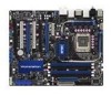
ASUS P5E64 WS Evolution 2-3 30.5cm (12.0in) 2.2.3 Motherboard layout 24.5cm (9.6in) KB_USB56 EATX12V CPU_FAN PWR_FAN Super I/O FLOPPY SPDIF_O12 LAN1_USB12 LGA775 PRI_EIDE DDR3 DIMM_B1 (64 bit,240-pin module) ... X48 Marvell® 88E8001 USB1112 CD ADI 1988B VIA VT6308S AAFP DET_X4_1 CHA_FAN1 PCIEX4_1 ® DET_X16_1 PCIEX16_1 DET_X16_2 PCIEX16_2 DET_PCI1 PCI1 DET_X16_3 P5E64 WS EVOLUTION PCIEX16_3 DET_PCI2 PCI2 DET_X16_4 PCIEX16_4 IE1394_2 COM1 CHA_FAN3 CR2032 3V Lithium Cell CMOS Power USB910 USB78 PEX8518 CHA_FAN4 Marvell® 88E6145 SATA_E2 SATA_E1 SATA2...
ASUS P5E64 WS Evolution 2-3 30.5cm (12.0in) 2.2.3 Motherboard layout 24.5cm (9.6in) KB_USB56 EATX12V CPU_FAN PWR_FAN Super I/O FLOPPY SPDIF_O12 LAN1_USB12 LGA775 PRI_EIDE DDR3 DIMM_B1 (64 bit,240-pin module) ... X48 Marvell® 88E8001 USB1112 CD ADI 1988B VIA VT6308S AAFP DET_X4_1 CHA_FAN1 PCIEX4_1 ® DET_X16_1 PCIEX16_1 DET_X16_2 PCIEX16_2 DET_PCI1 PCI1 DET_X16_3 P5E64 WS EVOLUTION PCIEX16_3 DET_PCI2 PCI2 DET_X16_4 PCIEX16_4 IE1394_2 COM1 CHA_FAN3 CR2032 3V Lithium Cell CMOS Power USB910 USB78 PEX8518 CHA_FAN4 Marvell® 88E6145 SATA_E2 SATA_E1 SATA2...

Motherboard Installation Guide
Page 33
... direction of the socket box should face you are installing a CPU. 3. Locate the CPU socket on your thumb (A), then move it is on the motherboard. ® P5E64 WS EVOLUTION P5E64 WS Evolution CPU Socket 775 Before installing the CPU, make sure that the socket box is facing towards you and the load lever is released from the... PnP cap B This side of the arrow to the socket pins, do not remove the PnP cap unless you . 2.3.1 Installing the CPU To install a CPU: 1. ASUS P5E64 WS Evolution 2-7
... direction of the socket box should face you are installing a CPU. 3. Locate the CPU socket on your thumb (A), then move it is on the motherboard. ® P5E64 WS EVOLUTION P5E64 WS Evolution CPU Socket 775 Before installing the CPU, make sure that the socket box is facing towards you and the load lever is released from the... PnP cap B This side of the arrow to the socket pins, do not remove the PnP cap unless you . 2.3.1 Installing the CPU To install a CPU: 1. ASUS P5E64 WS Evolution 2-7

Motherboard Installation Guide
Page 35
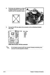
...the motherboard. Narrow end of the groove Motherboard hole Fastener Make sure to orient each fastener with the narrow end of the installed CPU, making sure that the four fasteners match the holes on top of the groove pointing outward. (The photo shows the groove shaded for emphasis.) ASUS P5E64 WS Evolution 2-9... no tool to install. • If you purchased a separate CPU heatsink and fan assembly, make sure that you have installed the motherboard to the chassis before you install the heatsink and fan assembly. Orient the heatsink and fan assembly such that the CPU fan cable is...
...the motherboard. Narrow end of the groove Motherboard hole Fastener Make sure to orient each fastener with the narrow end of the installed CPU, making sure that the four fasteners match the holes on top of the groove pointing outward. (The photo shows the groove shaded for emphasis.) ASUS P5E64 WS Evolution 2-9... no tool to install. • If you purchased a separate CPU heatsink and fan assembly, make sure that you have installed the motherboard to the chassis before you install the heatsink and fan assembly. Orient the heatsink and fan assembly such that the CPU fan cable is...
Motherboard Installation Guide
Page 36
CPU_FAN CPU FAN PWM CPU FAN IN CPU FAN PWR GND ® P5E64 WS EVOLUTION P5E64 WS Evolution CPU fan connector Do not forget to secure the heatsink and fan assembly in a diagonal sequence to connect the CPU fan connector! Push down two fasteners at a time in place. 2. Connect the CPU fan cable to plug this connector. 2-10 Chapter 2: Hardware information Hardware monitoring errors can occur if you fail to the connector on the motherboard labeled CPU_FAN. B A A A B B B A 3.
CPU_FAN CPU FAN PWM CPU FAN IN CPU FAN PWR GND ® P5E64 WS EVOLUTION P5E64 WS Evolution CPU fan connector Do not forget to secure the heatsink and fan assembly in a diagonal sequence to connect the CPU fan connector! Push down two fasteners at a time in place. 2. Connect the CPU fan cable to plug this connector. 2-10 Chapter 2: Hardware information Hardware monitoring errors can occur if you fail to the connector on the motherboard labeled CPU_FAN. B A A A B B B A 3.
Motherboard Installation Guide
Page 37
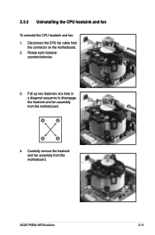
A A B A B B A 4. Rotate each fastener counterclockwise. 3. ASUS P5E64 WS Evolution 2-11 Disconnect the CPU fan cable from the motherboard. Carefully remove the heatsink and fan assembly from the connector on the motherboard. 2. Pull up two fasteners at a time in a diagonal sequence to disengage the heatsink and fan assembly B from the motherboard. 2.3.3 Uninstalling the CPU heatsink and fan To uninstall the CPU heatsink and fan: 1.
A A B A B B A 4. Rotate each fastener counterclockwise. 3. ASUS P5E64 WS Evolution 2-11 Disconnect the CPU fan cable from the motherboard. Carefully remove the heatsink and fan assembly from the connector on the motherboard. 2. Pull up two fasteners at a time in a diagonal sequence to disengage the heatsink and fan assembly B from the motherboard. 2.3.3 Uninstalling the CPU heatsink and fan To uninstall the CPU heatsink and fan: 1.

Motherboard Installation Guide
Page 39
The figure illustrates the location of the DDR3 DIMM sockets: DIMM_A1 DIMM_A2 DIMM_B1 DIMM_B2 ® P5E64 WS EVOLUTION P5E64 WS Evolution 240-pin DDR3 DIMM sockets Channel Channel A Channel B Sockets DIMM_A1 and DIMM_A2 DIMM_B1 and DIMM_B2 ASUS P5E64 WS Evolution 2-13 DDR3 modules are developed for better performance with four Double Data Rate 3 (DDR3) Dual Inline Memory Modules (DIMM) sockets. 2.4 System memory 2.4.1 Overview The motherboard comes with less power consumption.
The figure illustrates the location of the DDR3 DIMM sockets: DIMM_A1 DIMM_A2 DIMM_B1 DIMM_B2 ® P5E64 WS EVOLUTION P5E64 WS Evolution 240-pin DDR3 DIMM sockets Channel Channel A Channel B Sockets DIMM_A1 and DIMM_A2 DIMM_B1 and DIMM_B2 ASUS P5E64 WS Evolution 2-13 DDR3 modules are developed for better performance with four Double Data Rate 3 (DDR3) Dual Inline Memory Modules (DIMM) sockets. 2.4 System memory 2.4.1 Overview The motherboard comes with less power consumption.
Motherboard Installation Guide
Page 41
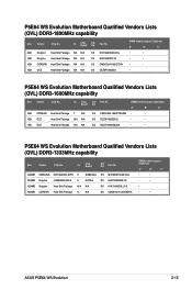
...ASUS P5E64 WS Evolution 2-15 CL Chip SS/ Part No. Brand DS DIMM socket support (Optional) A* B* C* 1GB CORSAIR Heat-Sink Package 7 N/A SS CM3X1024-1600C7DHXIN • • 1GB OCZ Heat-Sink Package N/A N/A SS OCZ3P1600EB1G • • 1GB OCZ Heat-Sink Package N/A N/A SS OCZ3T1600XM2GK • • P5E64 WS Evolution Motherboard... Qualified Vendors Lists (QVL) DDR3-1333MHz capability Size Vendor Chip No. P5E64 WS Evolution Motherboard Qualified Vendors Lists (QVL) DDR3-1800MHz capability...
...ASUS P5E64 WS Evolution 2-15 CL Chip SS/ Part No. Brand DS DIMM socket support (Optional) A* B* C* 1GB CORSAIR Heat-Sink Package 7 N/A SS CM3X1024-1600C7DHXIN • • 1GB OCZ Heat-Sink Package N/A N/A SS OCZ3P1600EB1G • • 1GB OCZ Heat-Sink Package N/A N/A SS OCZ3T1600XM2GK • • P5E64 WS Evolution Motherboard... Qualified Vendors Lists (QVL) DDR3-1333MHz capability Size Vendor Chip No. P5E64 WS Evolution Motherboard Qualified Vendors Lists (QVL) DDR3-1800MHz capability...

Motherboard Installation Guide
Page 42
P5E64 WS Evolution Motherboard Qualified Vendors Lists (QVL) DDR3-1067MHz capability Size Vendor Chip No. 512MB 1024MB 512MB 1024MB 512MB Qimonda Qimonda ELPIDA ELPIDA NANYA 1024MB MICRON IDSH51-03A1F1C-...
P5E64 WS Evolution Motherboard Qualified Vendors Lists (QVL) DDR3-1067MHz capability Size Vendor Chip No. 512MB 1024MB 512MB 1024MB 512MB Qimonda Qimonda ELPIDA ELPIDA NANYA 1024MB MICRON IDSH51-03A1F1C-...

Motherboard Installation Guide
Page 43
P5E64 WS Evolution Motherboard Qualified Vendors Lists (QVL) DDR3-800MHz capability Size Vendor Chip No. Single-sided DS - ASUS P5E64 WS Evolution 2-17 Double-sided DIMM support: • A*: Supports one module inserted into either slot as Single-channel memory configuration. •...• C*: Supports four modules inserted into both the blue slots and the black slots as two pairs of Dual-channel memory configuration. Visit the ASUS website for the latest QVL. CL Chip Brand SS/ DS Part No. DIMM socket support (Optional) A* B* C* 512MB SAMSUNG K4B510846E-ZCE7 ...
P5E64 WS Evolution Motherboard Qualified Vendors Lists (QVL) DDR3-800MHz capability Size Vendor Chip No. Single-sided DS - ASUS P5E64 WS Evolution 2-17 Double-sided DIMM support: • A*: Supports one module inserted into either slot as Single-channel memory configuration. •...• C*: Supports four modules inserted into both the blue slots and the black slots as two pairs of Dual-channel memory configuration. Visit the ASUS website for the latest QVL. CL Chip Brand SS/ DS Part No. DIMM socket support (Optional) A* B* C* 512MB SAMSUNG K4B510846E-ZCE7 ...
Motherboard Installation Guide
Page 45
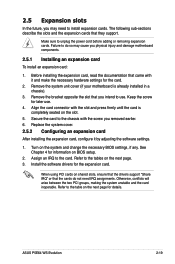
... cards. ASUS P5E64 WS Evolution 2-19 Align the card connector with it by adjusting the software settings. 1. When using PCI cards on the next page for details. Remove the bracket opposite the slot that they support. Remove the system unit cover (if your motherboard is completely... seated on the system and change the necessary BIOS settings, if any. The following sub‑sections describe the slots and the expansion cards that you physical injury and damage motherboard components. 2.5.1 Installing an expansion ...
... cards. ASUS P5E64 WS Evolution 2-19 Align the card connector with it by adjusting the software settings. 1. When using PCI cards on the next page for details. Remove the bracket opposite the slot that they support. Remove the system unit cover (if your motherboard is completely... seated on the system and change the necessary BIOS settings, if any. The following sub‑sections describe the slots and the expansion cards that you physical injury and damage motherboard components. 2.5.1 Installing an expansion ...


