
User Manual
Page 1
Motherboard
Motherboard

User Manual
Page 1
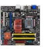
P5E-VM SE Motherboard
P5E-VM SE Motherboard
User Manual
Page 3
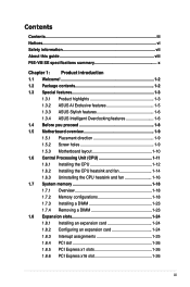
Contents Contents...iii Notices...vi Safety information vii About this guide viii P5E-VM SE specifications summary x Chapter 1: Product introduction 1.1 Welcome 1-2 1.2 Package contents 1-2 1.3 Special features 1-3 1.3.1 Product highlights 1-3 1.3.2 ASUS AI Exclusive features 1-5 1.3.3 ASUS Stylish features 1-6 1.3.4 ASUS Intelligent Overclocking features 1-6 1.4 Before you proceed 1-8 1.5 Motherboard overview 1-9 1.5.1 Placement direction 1-9 1.5.2 Screw holes 1-9 1.5.3 Motherboard layout 1-10 1.6 Central Processing Unit (CPU 1-11 1.6.1 Installing the CPU 1-12...
Contents Contents...iii Notices...vi Safety information vii About this guide viii P5E-VM SE specifications summary x Chapter 1: Product introduction 1.1 Welcome 1-2 1.2 Package contents 1-2 1.3 Special features 1-3 1.3.1 Product highlights 1-3 1.3.2 ASUS AI Exclusive features 1-5 1.3.3 ASUS Stylish features 1-6 1.3.4 ASUS Intelligent Overclocking features 1-6 1.4 Before you proceed 1-8 1.5 Motherboard overview 1-9 1.5.1 Placement direction 1-9 1.5.2 Screw holes 1-9 1.5.3 Motherboard layout 1-10 1.6 Central Processing Unit (CPU 1-11 1.6.1 Installing the CPU 1-12...

User Manual
Page 7
...product in any damage, contact your dealer immediately. • To avoid short circuits, keep paper clips, screws, and staples away from the motherboard, ensure that came with the product, contact a qualified service technician or your area. Check local regulations for the devices are unplugged before ... technician or your power supply is broken, do not try to the correct voltage in municipal waste. Operation safety • Before installing the motherboard and adding devices on a stable surface. • If you detect any area where it may become wet. • Place the product ...
...product in any damage, contact your dealer immediately. • To avoid short circuits, keep paper clips, screws, and staples away from the motherboard, ensure that came with the product, contact a qualified service technician or your area. Check local regulations for the devices are unplugged before ... technician or your power supply is broken, do not try to the correct voltage in municipal waste. Operation safety • Before installing the motherboard and adding devices on a stable surface. • If you detect any area where it may become wet. • Place the product ...
User Manual
Page 8
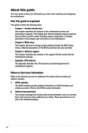
Optional documentation Your product package may have to change system settings through the BIOS Setup menus. ASUS websites The ASUS website provides updated information on the motherboard. • Chapter 2: BIOS setup This chapter tells how to perform when installing system components. These documents ..., such as warranty flyers, that the motherboard supports. Detailed descriptions of the BIOS parameters are not part of the motherboard and the new technology it supports. Where to find more information Refer to the ASUS contact information. 2. viii This chapter also...
Optional documentation Your product package may have to change system settings through the BIOS Setup menus. ASUS websites The ASUS website provides updated information on the motherboard. • Chapter 2: BIOS setup This chapter tells how to perform when installing system components. These documents ..., such as warranty flyers, that the motherboard supports. Detailed descriptions of the BIOS parameters are not part of the motherboard and the new technology it supports. Where to find more information Refer to the ASUS contact information. 2. viii This chapter also...

User Manual
Page 10
... with Intel® 05B/05A/06 processors Supports Intel® 45nm multi-core CPUs * This motherboard supports FSB 1333/1066/800 MHz Intel® G35 / ICH9 with max. P5E-VM SE specifications summary CPU Chipset System bus Memory VGA Expansion slots Storage LAN Audio IEEE 1394 USB LGA775 ...socket for up to 2 PATA devices Atheros L1 PCI-E Gigabit LAN controller PCIe Gb LAN controller Realtek® ALC883 8-channel High-Definition Audio CODEC - ASUS Noise...
... with Intel® 05B/05A/06 processors Supports Intel® 45nm multi-core CPUs * This motherboard supports FSB 1333/1066/800 MHz Intel® G35 / ICH9 with max. P5E-VM SE specifications summary CPU Chipset System bus Memory VGA Expansion slots Storage LAN Audio IEEE 1394 USB LGA775 ...socket for up to 2 PATA devices Atheros L1 PCI-E Gigabit LAN controller PCIe Gb LAN controller Realtek® ALC883 8-channel High-Definition Audio CODEC - ASUS Noise...
User Manual
Page 13
It includes description of the motherboard and the new technology it supports. Chapter 1: 1Product introduction This chapter describes the features of the jumpers and connectors on the motherboard. This chapter also lists the hardware setup procedures that you have to perform when installing system components.
It includes description of the motherboard and the new technology it supports. Chapter 1: 1Product introduction This chapter describes the features of the jumpers and connectors on the motherboard. This chapter also lists the hardware setup procedures that you have to perform when installing system components.
User Manual
Page 14
Retail version only) ASUS motherboard support CD ASUS Superb Software Library CD User guide If any of ASUS quality motherboards! Before you for the following items. Motherboard Cables Accessories Application CD Documentation ASUS P5E-VM SE 1 x Serial ATA signal cable 1 x Serial ATA power cable 1 x Ultra DMA 133/100/66 cable 1 x Floppy disk drive cable I/O shield 1 x ASUS Q-Connector Kit (USB, system panel; 1.1 Welcome...
Retail version only) ASUS motherboard support CD ASUS Superb Software Library CD User guide If any of ASUS quality motherboards! Before you for the following items. Motherboard Cables Accessories Application CD Documentation ASUS P5E-VM SE 1 x Serial ATA signal cable 1 x Serial ATA power cable 1 x Ultra DMA 133/100/66 cable 1 x Floppy disk drive cable I/O shield 1 x ASUS Q-Connector Kit (USB, system panel; 1.1 Welcome...
User Manual
Page 15
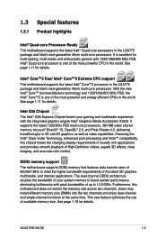
...channel DDR2 architecture doubles the bandwidth of your gaming and multimedia experience with the integrated graphics engine Intel® Graphics Media Accelerator X3500. ASUS P5E-VM SE 1-3 With the new Intel® Core™ microarchitecture technology and 1333/1066/800 MHz FSB, the Intel® Core™2 ...-core processors. See page 1-18 for details. Intel® Core™2 Duo/ Intel® Core™2 Extreme CPU support This motherboard supports the latest Intel® Core™2 processor in 3D and 2D graphics as well as video capabilities. Featuring the Intel® ...
...channel DDR2 architecture doubles the bandwidth of your gaming and multimedia experience with the integrated graphics engine Intel® Graphics Media Accelerator X3500. ASUS P5E-VM SE 1-3 With the new Intel® Core™ microarchitecture technology and 1333/1066/800 MHz FSB, the Intel® Core™2 ...-core processors. See page 1-18 for details. Intel® Core™2 Duo/ Intel® Core™2 Extreme CPU support This motherboard supports the latest Intel® Core™2 processor in 3D and 2D graphics as well as video capabilities. Featuring the Intel® ...
User Manual
Page 16
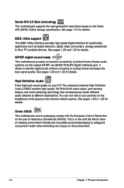
... network games. It allows to transfer digital audio without converting to your PC! See pages 1-29 and 1-32 for details. Green ASUS This motherboard and its packaging comply with the ASUS vision of Hazardous Substances (RoHS). IEEE 1394a support The IEEE 1394a interface provides high speed digital interface for audio/video appliances such...
... network games. It allows to transfer digital audio without converting to your PC! See pages 1-29 and 1-32 for details. Green ASUS This motherboard and its packaging comply with the ASUS vision of Hazardous Substances (RoHS). IEEE 1394a support The IEEE 1394a interface provides high speed digital interface for audio/video appliances such...
User Manual
Page 17
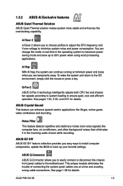
...system loading to the OS environment, simply click the mouse or press a key. See pages 1-34, 2-30, and 2-31 for details. ASUS P5E-VM SE 1-5 ASUS Q-Connector ASUS Q-Connector allows you easy ways to install computer components, update the BIOS or back up to maximum power saving mode and save up your ... panel cables one at minimum power and noise when you to choose profiles to adjust the CPU frequency and Vcore voltage to the motherboard. ASUS Crystal Sound This feature can change the mode in real-time in the incoming audio stream while recording. You can enhance speech-centric...
...system loading to the OS environment, simply click the mouse or press a key. See pages 1-34, 2-30, and 2-31 for details. ASUS P5E-VM SE 1-5 ASUS Q-Connector ASUS Q-Connector allows you easy ways to install computer components, update the BIOS or back up to maximum power saving mode and save up your ... panel cables one at minimum power and noise when you to choose profiles to adjust the CPU frequency and Vcore voltage to the motherboard. ASUS Crystal Sound This feature can change the mode in real-time in the incoming audio stream while recording. You can enhance speech-centric...
User Manual
Page 19
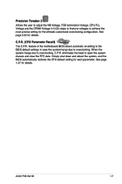
... overclocking. See page 2-20 for details. When the system hangs due to open the system chassis and clear the RTC data. ASUS P5E-VM SE 1-7 See page 1-27 for details. feature of the motherboard BIOS allows automatic re-setting to the BIOS default settings in 0.02v steps to finetune voltages to achieve the most precise...
... overclocking. See page 2-20 for details. When the system hangs due to open the system chassis and clear the RTC data. ASUS P5E-VM SE 1-7 See page 1-27 for details. feature of the motherboard BIOS allows automatic re-setting to the BIOS default settings in 0.02v steps to finetune voltages to achieve the most precise...
User Manual
Page 20
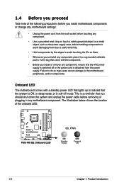
...in sleep mode, or in any component, place it on a grounded antistatic pad or in the bag that lights up to the motherboard, peripherals, and/or components. The illustration below shows the location of the following precautions before handling components to avoid damaging them due ...on them. • Whenever you uninstall any motherboard component. Failure to do so may cause severe damage to indicate that the ATX power supply is switched off mode. 1.4 Before you proceed Take note of the onboard LED. ® P5E-VM SE P5E-VM SE Onboard LED SB_PWR ON Standby Power OFF Powered ...
...in sleep mode, or in any component, place it on a grounded antistatic pad or in the bag that lights up to the motherboard, peripherals, and/or components. The illustration below shows the location of the following precautions before handling components to avoid damaging them due ...on them. • Whenever you uninstall any motherboard component. Failure to do so may cause severe damage to indicate that the ATX power supply is switched off mode. 1.4 Before you proceed Take note of the onboard LED. ® P5E-VM SE P5E-VM SE Onboard LED SB_PWR ON Standby Power OFF Powered ...
User Manual
Page 21
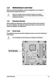
... the correct orientation. Doing so can cause you physical injury and damage motherboard components. 1.5.1 Placement direction When installing the motherboard, make sure that you install the motherboard, study the configuration of the chassis ® P5E-VM SE ASUS P5E-VM SE 1-9 Failure to do so can damage the motherboard. Make sure to the chassis. Place this side towards the rear of...
... the correct orientation. Doing so can cause you physical injury and damage motherboard components. 1.5.1 Placement direction When installing the motherboard, make sure that you install the motherboard, study the configuration of the chassis ® P5E-VM SE ASUS P5E-VM SE 1-9 Failure to do so can damage the motherboard. Make sure to the chassis. Place this side towards the rear of...
User Manual
Page 23
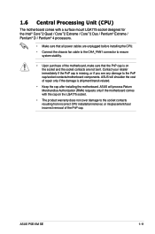
... contacts/motherboard components. ASUS will process Return Merchandise Authorization (RMA) requests only if the motherboard comes with a surface mount LGA775 socket designed for the Intel® Core™2 Quad / Core™2 Extreme / Core™2 Duo / Pentium® Extreme / Pentium® D / Pentium® 4 processors. • Make sure that all power cables are not bent. ASUS P5E-VM SE...
... contacts/motherboard components. ASUS will process Return Merchandise Authorization (RMA) requests only if the motherboard comes with a surface mount LGA775 socket designed for the Intel® Core™2 Quad / Core™2 Extreme / Core™2 Duo / Pentium® Extreme / Pentium® D / Pentium® 4 processors. • Make sure that all power cables are not bent. ASUS P5E-VM SE...
User Manual
Page 24
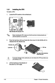
... face you are installing a CPU. 3. Retention tab A Load lever PnP cap B This side of the arrow to the left (B) until it is on the motherboard. ® P5E-VM SE P5E-VM SE CPU Socket 775 Before installing the CPU, make sure that the cam box is facing towards you and the load lever is released from the...
... face you are installing a CPU. 3. Retention tab A Load lever PnP cap B This side of the arrow to the left (B) until it is on the motherboard. ® P5E-VM SE P5E-VM SE CPU Socket 775 Before installing the CPU, make sure that the cam box is facing towards you and the load lever is released from the...
User Manual
Page 25
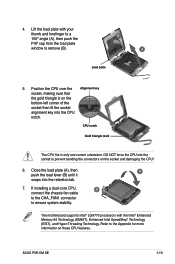
... CPU! 6. If installing a dual-core CPU, B connect the chassis fan cable to the CHA_FAN1 connector to remove (B). ASUS P5E-VM SE 1-13 4. CPU notch Gold triangle mark The CPU fits in only one correct orientation. The motherboard supports Intel® LGA775 processors with your thumb and forefinger to a 100º angle (A), then push the PnP...
... CPU! 6. If installing a dual-core CPU, B connect the chassis fan cable to the CHA_FAN1 connector to remove (B). ASUS P5E-VM SE 1-13 4. CPU notch Gold triangle mark The CPU fits in only one correct orientation. The motherboard supports Intel® LGA775 processors with your thumb and forefinger to a 100º angle (A), then push the PnP...
User Manual
Page 26
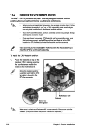
Place the heatsink on the motherboard. If you buy a boxed Intel® processor, the package includes the CPU fan and heatsink assembly. Orient ...before you install the CPU fan and heatsink assembly. To install the CPU heatsink and fan: 1. Narrow end of the groove Motherboard hole Fastener Make sure to orient each fastener with the narrow end of the installed CPU, making sure that the CPU fan.... • If you purchased a separate CPU heatsink and fan assembly, make sure that you have installed the motherboard to the chassis before you install the heatsink and fan assembly.
Place the heatsink on the motherboard. If you buy a boxed Intel® processor, the package includes the CPU fan and heatsink assembly. Orient ...before you install the CPU fan and heatsink assembly. To install the CPU heatsink and fan: 1. Narrow end of the groove Motherboard hole Fastener Make sure to orient each fastener with the narrow end of the installed CPU, making sure that the CPU fan.... • If you purchased a separate CPU heatsink and fan assembly, make sure that you have installed the motherboard to the chassis before you install the heatsink and fan assembly.
User Manual
Page 27
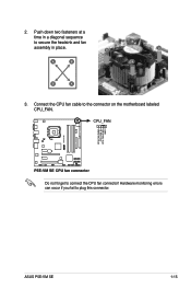
A A A B B B A 3. Hardware monitoring errors can occur if you fail to connect the CPU fan connector! CPU_FAN ® P5E-VM SE CPU FAN PWM CPU FAN IN CPU FAN PWR GND P5E-VM SE CPU fan connector Do not forget to plug this connector. ASUS P5E-VM SE 1-15 Connect the CPU fan cable to secure the heatsink and fan B assembly in a diagonal sequence to the connector on the motherboard labeled CPU_FAN. 2. Push down two fasteners at a time in place.
A A A B B B A 3. Hardware monitoring errors can occur if you fail to connect the CPU fan connector! CPU_FAN ® P5E-VM SE CPU FAN PWM CPU FAN IN CPU FAN PWR GND P5E-VM SE CPU fan connector Do not forget to plug this connector. ASUS P5E-VM SE 1-15 Connect the CPU fan cable to secure the heatsink and fan B assembly in a diagonal sequence to the connector on the motherboard labeled CPU_FAN. 2. Push down two fasteners at a time in place.
User Manual
Page 28
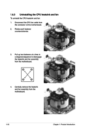
A A B A B B A 4. Pull up two fasteners at a time in a diagonal sequence to disengage the heatsink and fan assembly B from the motherboard. 1-16 Chapter 1: Product Introduction Carefully remove the heatsink and fan assembly from the motherboard. 1.6.3 Uninstalling the CPU heatsink and fan To uninstall the CPU heatsink and fan: 1. Disconnect the CPU fan cable from the connector on the motherboard. 2. Rotate each fastener counterclockwise. 3.
A A B A B B A 4. Pull up two fasteners at a time in a diagonal sequence to disengage the heatsink and fan assembly B from the motherboard. 1-16 Chapter 1: Product Introduction Carefully remove the heatsink and fan assembly from the motherboard. 1.6.3 Uninstalling the CPU heatsink and fan To uninstall the CPU heatsink and fan: 1. Disconnect the CPU fan cable from the connector on the motherboard. 2. Rotate each fastener counterclockwise. 3.


