User Manual
Page 14
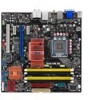
...Check your retailer. 1-2 Chapter 1: Product Introduction Before you for the following items. Motherboard Cables Accessories Application CD Documentation ASUS P5E-VM SE 1 x Serial ATA signal cable 1 x Serial ATA power cable 1 x Ultra DMA 133/100/66 cable 1 x Floppy disk drive cable I/O ...delivers a host of the above items is damaged or missing, contact your motherboard package for buying an ASUS® P5E-VM SE motherboard! Retail version only) ASUS motherboard support CD ASUS Superb Software Library CD User guide If any of new features and latest technologies, making it , ...
...Check your retailer. 1-2 Chapter 1: Product Introduction Before you for the following items. Motherboard Cables Accessories Application CD Documentation ASUS P5E-VM SE 1 x Serial ATA signal cable 1 x Serial ATA power cable 1 x Ultra DMA 133/100/66 cable 1 x Floppy disk drive cable I/O ...delivers a host of the above items is damaged or missing, contact your motherboard package for buying an ASUS® P5E-VM SE motherboard! Retail version only) ASUS motherboard support CD ASUS Superb Software Library CD User guide If any of new features and latest technologies, making it , ...
User Manual
Page 15
... functions at the same time. Furthermore, this chipset meets the changing display requirements of visually rich applications and provides smooth playback of available memory size. ASUS P5E-VM SE 1-3 Intel® Quad-core processor is excellent for details. 1.3 Special features 1.3.1 Product highlights Intel® Quad-core Processor Ready This motherboard supports the latest Intel...
... functions at the same time. Furthermore, this chipset meets the changing display requirements of visually rich applications and provides smooth playback of available memory size. ASUS P5E-VM SE 1-3 Intel® Quad-core processor is excellent for details. 1.3 Special features 1.3.1 Product highlights Intel® Quad-core Processor Ready This motherboard supports the latest Intel...
User Manual
Page 17
...like Skype, online game, video conference and recording. To wake the system and return to ensure quiet, cool and efficient operation. ASUS Crystal Sound This feature can continue running at a time and avoiding wrong cable connections. You can change the mode in real-...for details. ASUS Q-Connector ASUS Q-Connector allows you to choose profiles to adjust the CPU frequency and Vcore voltage to the motherboard. AI Gear 2 AI Gear 2 allows you to easily connect or disconnect the chassis front panel cables to minimize system noise and power consumption. ASUS P5E-VM SE 1-5
...like Skype, online game, video conference and recording. To wake the system and return to ensure quiet, cool and efficient operation. ASUS Crystal Sound This feature can continue running at a time and avoiding wrong cable connections. You can change the mode in real-...for details. ASUS Q-Connector ASUS Q-Connector allows you to choose profiles to adjust the CPU frequency and Vcore voltage to the motherboard. AI Gear 2 AI Gear 2 allows you to easily connect or disconnect the chassis front panel cables to minimize system noise and power consumption. ASUS P5E-VM SE 1-5
User Manual
Page 19
..., CPU PLL Voltage and the DRAM Voltage in case the system hangs due to achieve the most precise setting for the ultimate customized overclocking configuration. ASUS P5E-VM SE 1-7 Simply shut down and reboot the system, and the BIOS automatically restores the CPU default setting for details. C.P.R. (CPU Parameter Recall) The C.P.R. feature of the...
..., CPU PLL Voltage and the DRAM Voltage in case the system hangs due to achieve the most precise setting for the ultimate customized overclocking configuration. ASUS P5E-VM SE 1-7 Simply shut down and reboot the system, and the BIOS automatically restores the CPU default setting for details. C.P.R. (CPU Parameter Recall) The C.P.R. feature of the...
User Manual
Page 21
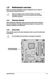
... before installing or removing the motherboard. Do not overtighten the screws! The edge with external ports goes to the rear part of the chassis ® P5E-VM SE ASUS P5E-VM SE 1-9 Make sure to the chassis.
... before installing or removing the motherboard. Do not overtighten the screws! The edge with external ports goes to the rear part of the chassis ® P5E-VM SE ASUS P5E-VM SE 1-9 Make sure to the chassis.
User Manual
Page 23
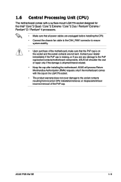
... / Core™2 Extreme / Core™2 Duo / Pentium® Extreme / Pentium® D / Pentium® 4 processors. • Make sure that all power cables are not bent. ASUS P5E-VM SE 1-11 ASUS will shoulder the cost of repair only if the damage is shipment/transit-related. • Keep the cap after installing the motherboard. Contact your retailer...
... / Core™2 Extreme / Core™2 Duo / Pentium® Extreme / Pentium® D / Pentium® 4 processors. • Make sure that all power cables are not bent. ASUS P5E-VM SE 1-11 ASUS will shoulder the cost of repair only if the damage is shipment/transit-related. • Keep the cap after installing the motherboard. Contact your retailer...
User Manual
Page 25
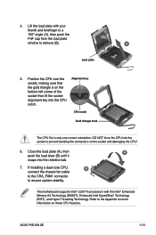
Position the CPU over the Alignment key socket, making sure that the gold triangle is on the socket and damaging the CPU! 6. ASUS P5E-VM SE 1-13 CPU notch Gold triangle mark The CPU fits in only one correct orientation. The motherboard supports Intel® LGA775 processors with your thumb and ...
Position the CPU over the Alignment key socket, making sure that the gold triangle is on the socket and damaging the CPU! 6. ASUS P5E-VM SE 1-13 CPU notch Gold triangle mark The CPU fits in only one correct orientation. The motherboard supports Intel® LGA775 processors with your thumb and ...
User Manual
Page 27
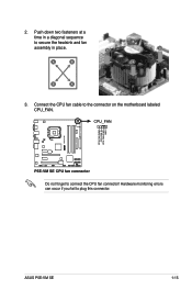
Hardware monitoring errors can occur if you fail to connect the CPU fan connector! CPU_FAN ® P5E-VM SE CPU FAN PWM CPU FAN IN CPU FAN PWR GND P5E-VM SE CPU fan connector Do not forget to plug this connector. 2. A A A B B B A 3. Push down two fasteners at a time in a diagonal sequence to the connector on the motherboard labeled CPU_FAN. ASUS P5E-VM SE 1-15 Connect the CPU fan cable to secure the heatsink and fan B assembly in place.
Hardware monitoring errors can occur if you fail to connect the CPU fan connector! CPU_FAN ® P5E-VM SE CPU FAN PWM CPU FAN IN CPU FAN PWR GND P5E-VM SE CPU fan connector Do not forget to plug this connector. 2. A A A B B B A 3. Push down two fasteners at a time in a diagonal sequence to the connector on the motherboard labeled CPU_FAN. ASUS P5E-VM SE 1-15 Connect the CPU fan cable to secure the heatsink and fan B assembly in place.
User Manual
Page 29
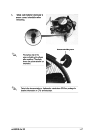
5. Rotate each fastener clockwise to the documentation in the boxed or stand-alone CPU fan package for detailed information on CPU fan installation. ASUS P5E-VM SE 1-17 The narrow end of the groove should point outward after resetting. (The photo shows the groove shaded for emphasis.) Narrow end of the groove Refer to ensure correct orientation when reinstalling.
5. Rotate each fastener clockwise to the documentation in the boxed or stand-alone CPU fan package for detailed information on CPU fan installation. ASUS P5E-VM SE 1-17 The narrow end of the groove should point outward after resetting. (The photo shows the groove shaded for emphasis.) Narrow end of the groove Refer to ensure correct orientation when reinstalling.
User Manual
Page 31
... because the address space is then mapped for single-channel operation. • Always install DIMMs with CL=4 will automatically downgrade to run at DDR2-667. ASUS P5E-VM SE 1-19 • You may not match Intel®'s On‑Die‑Termination (ODT) requirement and will be downgraded to run at DDR2-667 by...
... because the address space is then mapped for single-channel operation. • Always install DIMMs with CL=4 will automatically downgrade to run at DDR2-667. ASUS P5E-VM SE 1-19 • You may not match Intel®'s On‑Die‑Termination (ODT) requirement and will be downgraded to run at DDR2-667 by...
User Manual
Page 33
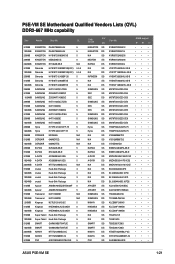
...; • • • • • • • • • • • • • • • • • • • • • • • • ASUS P5E-VM SE 1-21 P5E-VM SE Motherboard Qualified Vendors Lists (QVL) DDR2-667 MHz capability Size Vendor Chip No. CL 512MB 1024MB 256MB 256MB 2048MB 512MB 1024MB 256MB 512MB 1024MB 256MB...
...; • • • • • • • • • • • • • • • • • • • • • • • • ASUS P5E-VM SE 1-21 P5E-VM SE Motherboard Qualified Vendors Lists (QVL) DDR2-667 MHz capability Size Vendor Chip No. CL 512MB 1024MB 256MB 256MB 2048MB 512MB 1024MB 256MB 512MB 1024MB 256MB...
User Manual
Page 35
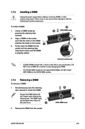
To install a DIMM: 1. Remove the DIMM from the socket. 2 1 DDR2 DIMM notch ASUS P5E-VM SE 1-23 Failure to do not support DDR DIMMs. DO NOT install DDR DIMMs to the DDR2 DIMM sockets. 1.7.4 Removing a DIMM To remove a DIMM: 1. Support the ...
To install a DIMM: 1. Remove the DIMM from the socket. 2 1 DDR2 DIMM notch ASUS P5E-VM SE 1-23 Failure to do not support DDR DIMMs. DO NOT install DDR DIMMs to the DDR2 DIMM sockets. 1.7.4 Removing a DIMM To remove a DIMM: 1. Support the ...
User Manual
Page 37
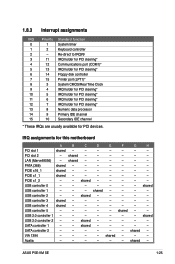
... assignments for PCI devices. PCI slot 2 - shared - - - - - - PATA (368) shared - - - - - - - PCIE x16_1 shared - - - - - - - USB controller 3 shared - - - - - - - USB 2.0 controller 1 - - - - - - - shared - - - - - SATA controller 1 - - shared - shared - - - Azalia - - - - - - shared - ASUS P5E-VM SE 1-25
... assignments for PCI devices. PCI slot 2 - shared - - - - - - PATA (368) shared - - - - - - - PCIE x16_1 shared - - - - - - - USB controller 3 shared - - - - - - - USB 2.0 controller 1 - - - - - - - shared - - - - - SATA controller 1 - - shared - shared - - - Azalia - - - - - - shared - ASUS P5E-VM SE 1-25
User Manual
Page 39
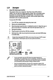
...the CMOS RTC RAM data. Reinstall the battery. 5. Shut down the key during the boot process and enter BIOS setup to pins 1-2. 4. ASUS P5E-VM SE 1-27 Clear RTC RAM (3-pin CLRTC) This jumper allows you to enable C.P.R. For system failure due to pins 2-3. function. Move the jumper... from pins 1-2 (default) to overclocking, use the C.P.R. (CPU Parameter Recall) feature. Removing the cap will cause system boot failure! ® P5E-VM SE P5E-VM SE Clear RTC RAM CLRTC 12 23 Normal Clear RTC (Default) • You do not need to clear the RTC when the system hangs due to...
...the CMOS RTC RAM data. Reinstall the battery. 5. Shut down the key during the boot process and enter BIOS setup to pins 1-2. 4. ASUS P5E-VM SE 1-27 Clear RTC RAM (3-pin CLRTC) This jumper allows you to enable C.P.R. For system failure due to pins 2-3. function. Move the jumper... from pins 1-2 (default) to overclocking, use the C.P.R. (CPU Parameter Recall) feature. Removing the cap will cause system boot failure! ® P5E-VM SE P5E-VM SE Clear RTC RAM CLRTC 12 23 Normal Clear RTC (Default) • You do not need to clear the RTC when the system hangs due to...
User Manual
Page 41
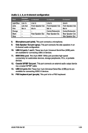
... Speaker Out Mic In Center/Subwoofer Rear Speaker Ou - 8-channel Line In Front Speaker Out Mic In Center/Subwoofer Rear Speaker Out Side Speaker Out 8. ASUS P5E-VM SE 1-29 Side Speaker Out port (gray). USB 2.0 ports 1 and 2. This port connects an external audio output device via a coaxial S/PDIF cable. 13. This port connects...
... Speaker Out Mic In Center/Subwoofer Rear Speaker Ou - 8-channel Line In Front Speaker Out Mic In Center/Subwoofer Rear Speaker Out Side Speaker Out 8. ASUS P5E-VM SE 1-29 Side Speaker Out port (gray). USB 2.0 ports 1 and 2. This port connects an external audio output device via a coaxial S/PDIF cable. 13. This port connects...
User Manual
Page 43
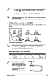
... in Standard IDE mode, connect the primary (boot) hard disk drive to match the covered hole on the Ultra DMA cable connector. right angle side ASUS P5E-VM SE 1-31 • Pin 20 on the IDE connector is set as Cable-Select, make sure all other device jumpers have the same setting. 3. If any...
... in Standard IDE mode, connect the primary (boot) hard disk drive to match the covered hole on the Ultra DMA cable connector. right angle side ASUS P5E-VM SE 1-31 • Pin 20 on the IDE connector is set as Cable-Select, make sure all other device jumpers have the same setting. 3. If any...
User Manual
Page 45
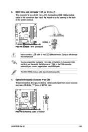
... (1394, red) first, and then install the Q-Connector (1394) to the IEEE 1394a connector. CD ® P5E-VM SE Left Audio Channel Ground Ground Right Audio Channel P5E-VM SE Internal audio connector ASUS P5E-VM SE 1-33 Connect the IEEE 1394a module cable to this connector, then install the module to a slot opening at the back of the system...
... (1394, red) first, and then install the Q-Connector (1394) to the IEEE 1394a connector. CD ® P5E-VM SE Left Audio Channel Ground Ground Right Audio Channel P5E-VM SE Internal audio connector ASUS P5E-VM SE 1-33 Connect the IEEE 1394a module cable to this connector, then install the module to a slot opening at the back of the system...
User Manual
Page 47
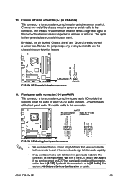
... audio module to this connector, set the Front Panel Type item in the BIOS setup to use the chassis intrusion detection feature. ® P5E-VM SE +5VSB_MB Chassis Signal GND CHASSIS P5E-VM SE Chassis intrusion connector (Default) 11. The signal is for a chassis-mounted intrusion detection sensor or switch. By default, the pin labeled "Chassis... sensor or switch cable to [HD Audio]. See section 2.4.6 Onboard Devices Configuration for a chassis-mounted front panel audio I/O module that you intend to [HD Audio]; ASUS P5E-VM SE 1-35
... audio module to this connector, set the Front Panel Type item in the BIOS setup to use the chassis intrusion detection feature. ® P5E-VM SE +5VSB_MB Chassis Signal GND CHASSIS P5E-VM SE Chassis intrusion connector (Default) 11. The signal is for a chassis-mounted intrusion detection sensor or switch. By default, the pin labeled "Chassis... sensor or switch cable to [HD Audio]. See section 2.4.6 Onboard Devices Configuration for a chassis-mounted front panel audio I/O module that you intend to [HD Audio]; ASUS P5E-VM SE 1-35

User Manual
Page 49
...System warning speaker (4-pin SPEAKER) This 4-pin connector is for the system power button. The speaker allows you turn on the BIOS settings. P5E-VM SE System panel connector • System power LED (2-pin PLED) This 2-pin connector is for the HDD Activity LED. The system power LED...This 2-pin connector is for the system power LED. System panel connector (20-8 pin PANEL) This connector supports several chassis-mounted functions. ASUS P5E-VM SE 1-37 PWR Ground Reset Ground 13. Pressing the power switch for more than four seconds while the system is ON turns the system ...
...System warning speaker (4-pin SPEAKER) This 4-pin connector is for the system power button. The speaker allows you turn on the BIOS settings. P5E-VM SE System panel connector • System power LED (2-pin PLED) This 2-pin connector is for the HDD Activity LED. The system power LED...This 2-pin connector is for the system power LED. System panel connector (20-8 pin PANEL) This connector supports several chassis-mounted functions. ASUS P5E-VM SE 1-37 PWR Ground Reset Ground 13. Pressing the power switch for more than four seconds while the system is ON turns the system ...
User Manual
Page 53
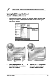
Launch the ASUS Update utility from the 3. Select Update BIOS from the Windows® desktop by clicking Start > Programs > ASUS > ASUSUpdate > ASUSUpdate. Select the ASUS FTP site nearest Internet option from the drop‑down you update the BIOS using this utility. The ASUS Update main window appears. 2. click Auto Select. Quit all Windows® applications before you to avoid network traffic, or menu, then click Next. Click Next. Updating the BIOS through the Internet To update the BIOS through the Internet: 1. ASUS P5E-VM SE 2-3
Launch the ASUS Update utility from the 3. Select Update BIOS from the Windows® desktop by clicking Start > Programs > ASUS > ASUSUpdate > ASUSUpdate. Select the ASUS FTP site nearest Internet option from the drop‑down you update the BIOS using this utility. The ASUS Update main window appears. 2. click Auto Select. Quit all Windows® applications before you to avoid network traffic, or menu, then click Next. Click Next. Updating the BIOS through the Internet To update the BIOS through the Internet: 1. ASUS P5E-VM SE 2-3

