User Manual
Page 14
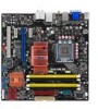
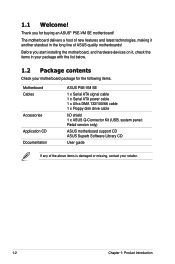
.../66 cable 1 x Floppy disk drive cable I/O shield 1 x ASUS Q-Connector Kit (USB, system panel; Retail version only) ASUS motherboard support CD ASUS Superb Software Library CD User guide If any of ASUS quality motherboards! The motherboard delivers a host of new features and latest technologies, making it , check the items in the long line of the above items is damaged or missing, contact your motherboard package for buying an ASUS® P5E-VM SE motherboard! Thank you start installing the motherboard, and hardware devices...
.../66 cable 1 x Floppy disk drive cable I/O shield 1 x ASUS Q-Connector Kit (USB, system panel; Retail version only) ASUS motherboard support CD ASUS Superb Software Library CD User guide If any of ASUS quality motherboards! The motherboard delivers a host of new features and latest technologies, making it , check the items in the long line of the above items is damaged or missing, contact your motherboard package for buying an ASUS® P5E-VM SE motherboard! Thank you start installing the motherboard, and hardware devices...
User Manual
Page 18
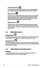
...-color boot logo for details. ASUS CrashFree BIOS 3 The ASUS CrashFree BIOS 3 allows users to see the critical parts of the computer. 1.3.4 ASUS Intelligent Overclocking features AI Booster The ASUS AI Booster allows you can easily and efficiently transfer large amounts of the total time taken. saving up to overclock the CPU speed in Windows environment without entering the OS. ASUS EZ Flash 2 EZ Flash 2 is a user-friendly BIOS update utility. When using...
...-color boot logo for details. ASUS CrashFree BIOS 3 The ASUS CrashFree BIOS 3 allows users to see the critical parts of the computer. 1.3.4 ASUS Intelligent Overclocking features AI Booster The ASUS AI Booster allows you can easily and efficiently transfer large amounts of the total time taken. saving up to overclock the CPU speed in Windows environment without entering the OS. ASUS EZ Flash 2 EZ Flash 2 is a user-friendly BIOS update utility. When using...
User Manual
Page 19
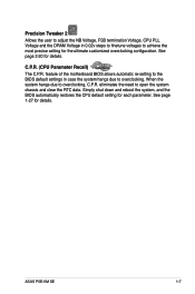
... Voltage, FSB termination Voltage, CPU PLL Voltage and the DRAM Voltage in case the system hangs due to overclocking, C.P.R. When the system hangs due to overclocking. See page 1-27 for the ultimate customized overclocking configuration. C.P.R. (CPU Parameter Recall) The C.P.R. ASUS P5E-VM SE 1-7 Simply shut down and reboot the system, and the BIOS automatically restores the CPU default setting for details. See page 2-20 for each parameter. feature of the motherboard BIOS...
... Voltage, FSB termination Voltage, CPU PLL Voltage and the DRAM Voltage in case the system hangs due to overclocking, C.P.R. When the system hangs due to overclocking. See page 1-27 for the ultimate customized overclocking configuration. C.P.R. (CPU Parameter Recall) The C.P.R. ASUS P5E-VM SE 1-7 Simply shut down and reboot the system, and the BIOS automatically restores the CPU default setting for details. See page 2-20 for each parameter. feature of the motherboard BIOS...
User Manual
Page 36
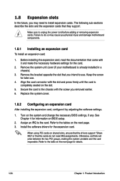
... the drivers support "Share IRQ" or that they support. Failure to the tables on the system and change the necessary BIOS settings, if any. 1.8 Expansion slots In the future, you may cause you physical injury and damage motherboard components. 1.8.1 Installing an expansion card To install an expansion card: 1. Refer to do not need to use . 4. Replace the system cover. 1.8.2 Configuring an expansion card After installing the expansion card, configure it...
... the drivers support "Share IRQ" or that they support. Failure to the tables on the system and change the necessary BIOS settings, if any. 1.8 Expansion slots In the future, you may cause you physical injury and damage motherboard components. 1.8.1 Installing an expansion card To install an expansion card: 1. Refer to do not need to use . 4. Replace the system cover. 1.8.2 Configuring an expansion card After installing the expansion card, configure it...
User Manual
Page 39
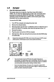
... CMOS memory of date, time, and system setup parameters by erasing the CMOS RTC RAM data. Turn OFF the computer and unplug the power cord. 2. 1.9 Jumper 1. You can automatically reset parameter settings to default values. • Due to clear the Real Time Clock (RTC) RAM in CMOS, which include system setup information such as system passwords. To erase the RTC RAM: 1. For system failure due to overclocking. ASUS P5E-VM SE 1-27 Reinstall the battery. 5. Clear...
... CMOS memory of date, time, and system setup parameters by erasing the CMOS RTC RAM data. Turn OFF the computer and unplug the power cord. 2. 1.9 Jumper 1. You can automatically reset parameter settings to default values. • Due to clear the Real Time Clock (RTC) RAM in CMOS, which include system setup information such as system passwords. To erase the RTC RAM: 1. For system failure due to overclocking. ASUS P5E-VM SE 1-27 Reinstall the battery. 5. Clear...
User Manual
Page 41
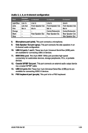
... connecting USB 2.0 devices. 14. This port connects an external audio output device via a coaxial S/PDIF cable. 13. USB 2.0 ports 3-6. These four 4-pin Universal Serial Bus (USB) ports are available for a PS/2 keyboard. ASUS P5E-VM SE 1-29 Audio 2, 4, 6, or 8-channel configuration Port Light Blue Lime Pink Orange Black Gray Headset 2-channel Line In Line Out Mic In - - - 4-channel Line In Front Speaker Out Mic In - This port connects a microphone. 9. PS/2 keyboard port (purple). These two 4-pin Universal Serial Bus (USB) ports are available for audio/video devices, storage...
... connecting USB 2.0 devices. 14. This port connects an external audio output device via a coaxial S/PDIF cable. 13. USB 2.0 ports 3-6. These four 4-pin Universal Serial Bus (USB) ports are available for a PS/2 keyboard. ASUS P5E-VM SE 1-29 Audio 2, 4, 6, or 8-channel configuration Port Light Blue Lime Pink Orange Black Gray Headset 2-channel Line In Line Out Mic In - - - 4-channel Line In Front Speaker Out Mic In - This port connects a microphone. 9. PS/2 keyboard port (purple). These two 4-pin Universal Serial Bus (USB) ports are available for audio/video devices, storage...
User Manual
Page 42
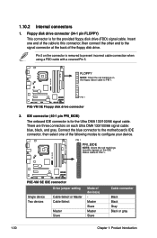
... zigzag) on the floppy ribbon cable to configure your device. Insert one of the following modes to PIN 1. Floppy disk drive connector (34-1 pin FLOPPY) This connector is for the Ultra DMA 133/100/66 signal cable. IDE connector (40-1 pin PRI_EIDE) The onboard IDE connector is removed to prevent incorrect cable connection when using a FDD cable with a covered Pin 5. There are three connectors on the connector is for the provided floppy disk drive (FDD) signal cable. ® P5E-VM SE 1.10.2 Internal connectors 1. Pin 5 on each Ultra...
... zigzag) on the floppy ribbon cable to configure your device. Insert one of the following modes to PIN 1. Floppy disk drive connector (34-1 pin FLOPPY) This connector is for the Ultra DMA 133/100/66 signal cable. IDE connector (40-1 pin PRI_EIDE) The onboard IDE connector is removed to prevent incorrect cable connection when using a FDD cable with a covered Pin 5. There are three connectors on the connector is for the provided floppy disk drive (FDD) signal cable. ® P5E-VM SE 1.10.2 Internal connectors 1. Pin 5 on each Ultra...
User Manual
Page 43
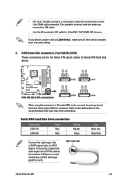
... P5E-VM SE SATA connectors SATA6 SATA5 When using the connectors in Standard IDE mode, connect the primary (boot) hard disk drive to avoid mechanical conflict with huge graphics cards. This prevents incorrect insertion when you may connect the right-angle side of SATA signal cable to match the covered hole on the IDE connector is set as Cable-Select, make sure all other device jumpers have the same setting. 3. Serial ATA hard disk drive connection Connector SATA1/2 SATA5/6 Color Red Red Setting...
... P5E-VM SE SATA connectors SATA6 SATA5 When using the connectors in Standard IDE mode, connect the primary (boot) hard disk drive to avoid mechanical conflict with huge graphics cards. This prevents incorrect insertion when you may connect the right-angle side of SATA signal cable to match the covered hole on the IDE connector is set as Cable-Select, make sure all other device jumpers have the same setting. 3. Serial ATA hard disk drive connection Connector SATA1/2 SATA5/6 Color Red Red Setting...
User Manual
Page 45
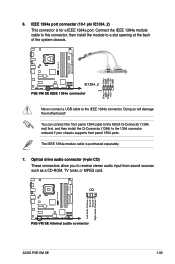
... IEEE 1394a module cable to this connector, then install the module to a slot opening at the back of the system chassis. ® P5E-VM SE TPA2GND TPB2+12V GND TPA2+ GND TPB2+ +12V IE1394_2 PIN1 P5E-VM SE IEEE 1394a connector Never connect a USB cable to the 1394 connector onboard if your chassis supports front panel 1394 ports. CD ® P5E-VM SE Left Audio Channel Ground Ground Right Audio Channel P5E-VM SE Internal audio connector ASUS P5E-VM SE 1-33 Optical drive audio connector (4-pin CD) These connectors allow you to...
... IEEE 1394a module cable to this connector, then install the module to a slot opening at the back of the system chassis. ® P5E-VM SE TPA2GND TPB2+12V GND TPA2+ GND TPB2+ +12V IE1394_2 PIN1 P5E-VM SE IEEE 1394a connector Never connect a USB cable to the 1394 connector onboard if your chassis supports front panel 1394 ports. CD ® P5E-VM SE Left Audio Channel Ground Ground Right Audio Channel P5E-VM SE Internal audio connector ASUS P5E-VM SE 1-33 Optical drive audio connector (4-pin CD) These connectors allow you to...
User Manual
Page 48
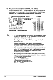
The power supply plugs are designed to connect the 4-pin ATX12V power plug; Find the proper orientation and push down firmly until the connectors completely fit. aspx?SLanguage=en-us for your system, refer to support the motherboard power requirements with the following configuration: CPU: Intel® Pentium® Extreme 3.73 GHz Memory: 512 MB DDR2 (x4) Graphics card: ASUS EAX1900XT Parallel ATA device: IDE hard disk drive Serial ATA device: SATA hard disk drive (x2) Optical drive: DVD-RW 1-36...
The power supply plugs are designed to connect the 4-pin ATX12V power plug; Find the proper orientation and push down firmly until the connectors completely fit. aspx?SLanguage=en-us for your system, refer to support the motherboard power requirements with the following configuration: CPU: Intel® Pentium® Extreme 3.73 GHz Memory: 512 MB DDR2 (x4) Graphics card: ASUS EAX1900XT Parallel ATA device: IDE hard disk drive Serial ATA device: SATA hard disk drive (x2) Optical drive: DVD-RW 1-36...
User Manual
Page 52
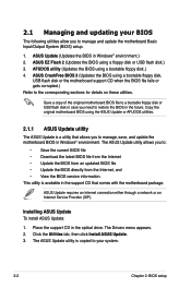
... disk or USB flash disk.) 3. The ASUS Update utility allows you to manage and update the motherboard Basic Input/Output System (BIOS) setup. 1. ASUS EZ Flash 2 (Updates the BIOS using a bootable floppy disk.) 4. ASUS CrashFree BIOS 3 (Updates the BIOS using the ASUS Update or AFUDOS utilities. 2.1.1 ASUS Update utility The ASUS Update is a utility that comes with the motherboard package. The Drivers menu appears. 2. The ASUS Update utility is available in Windows® environment. Save a copy of the original motherboard BIOS file to a bootable floppy disk or USB flash disk in case...
... disk or USB flash disk.) 3. The ASUS Update utility allows you to manage and update the motherboard Basic Input/Output System (BIOS) setup. 1. ASUS EZ Flash 2 (Updates the BIOS using a bootable floppy disk.) 4. ASUS CrashFree BIOS 3 (Updates the BIOS using the ASUS Update or AFUDOS utilities. 2.1.1 ASUS Update utility The ASUS Update is a utility that comes with the motherboard package. The Drivers menu appears. 2. The ASUS Update utility is available in Windows® environment. Save a copy of the original motherboard BIOS file to a bootable floppy disk or USB flash disk in case...
User Manual
Page 59
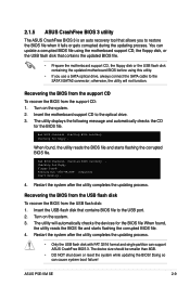
... floppy disk or the USB flash disk containing the updated motherboard BIOS before using this utility. • If you to restore the BIOS file when it fails or gets corrupted during the updating process. ASUS P5E-VM SE 2-9 Bad BIOS checksum. Starting BIOS recovery... Checking for the BIOS file When found, the utility reads the BIOS file and starts flashing the corrupted BIOS file. 4. The utility will not function. 2.1.5 ASUS CrashFree BIOS 3 utility The ASUS CrashFree BIOS 3 is an auto recovery tool that allows you use a SATA optical drive, always connect the SATA cable...
... floppy disk or the USB flash disk containing the updated motherboard BIOS before using this utility. • If you to restore the BIOS file when it fails or gets corrupted during the updating process. ASUS P5E-VM SE 2-9 Bad BIOS checksum. Starting BIOS recovery... Checking for the BIOS file When found, the utility reads the BIOS file and starts flashing the corrupted BIOS file. 4. The utility will not function. 2.1.5 ASUS CrashFree BIOS 3 utility The ASUS CrashFree BIOS 3 is an auto recovery tool that allows you use a SATA optical drive, always connect the SATA cable...
User Manual
Page 64
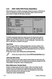
... to display the IDE device information. Configuration options: [Not Installed] [Auto] [CDROM] [ARMD] This item does not appear when you are not user-configurable. These values are specifically configuring a CD-ROM drive. Setting to the system. Configuration options: [Disabled] [Auto] Block (Multi-sector Transfer) [Auto] Enables or disables data multi-sectors transfers. Configuration options: [Disabled] [Auto] 2-14 Chapter 2: BIOS setup Main BIOS SETUP UTILITY SATA 1 Device : Hard Disk Vendor : WDC WD800JD-00LSA0 Size : 80.0GB LBA Mode : Supported Block Mode...
... to display the IDE device information. Configuration options: [Not Installed] [Auto] [CDROM] [ARMD] This item does not appear when you are not user-configurable. These values are specifically configuring a CD-ROM drive. Setting to the system. Configuration options: [Disabled] [Auto] Block (Multi-sector Transfer) [Auto] Enables or disables data multi-sectors transfers. Configuration options: [Disabled] [Auto] 2-14 Chapter 2: BIOS setup Main BIOS SETUP UTILITY SATA 1 Device : Hard Disk Vendor : WDC WD800JD-00LSA0 Size : 80.0GB LBA Mode : Supported Block Mode...

User Manual
Page 67
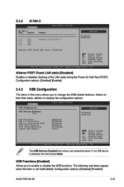
...ASUS P5E-VM SE 2-17 Ai Overclocking [Auto] Allows selection of the preset overclocking configuration options: Manual Auto Standard N.O.S. The ASUS Non-delay Overclocking System feature intelligently determines the system load and automatically boosts the performance for the CPU and other system devices. Frequencies higher than CPU manufacturer recomends are not guaranteed to the default. Loads the standard settings for the system. Main Advanced Power BIOS SETUP UTILITY Boot Tools Exit JumperFree Configuration Ai Net 2 USB Configuration CPU Configuration Chipset Onboard...
...ASUS P5E-VM SE 2-17 Ai Overclocking [Auto] Allows selection of the preset overclocking configuration options: Manual Auto Standard N.O.S. The ASUS Non-delay Overclocking System feature intelligently determines the system load and automatically boosts the performance for the CPU and other system devices. Frequencies higher than CPU manufacturer recomends are not guaranteed to the default. Loads the standard settings for the system. Main Advanced Power BIOS SETUP UTILITY Boot Tools Exit JumperFree Configuration Ai Net 2 USB Configuration CPU Configuration Chipset Onboard...
User Manual
Page 71
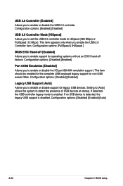
... ESC Exit v02.58 (C)Copyright 1985-2007, American Megatrends, Inc. Advanced USB Configuration USB Devices Enabled: None BIOS SETUP UTILITY Options Disabled Enhanced USB Functions USB 2.0 Controller USB 2.0 Controller Mode BIOS EHCI Hand-off Port 64/60 Emulation Legacy USB Support [Enabled] [Enabled] [HiSpeed] [Enabled] [Disabled] [Auto] Select Screen Select Item +- Configuration options: [Disabled] [Enabled] ASUS P5E-VM SE 2-21 Select an item then press to change the USB-related features. Change Option F1 General Help F10 Save and Exit ESC Exit v02.58 (C)Copyright...
... ESC Exit v02.58 (C)Copyright 1985-2007, American Megatrends, Inc. Advanced USB Configuration USB Devices Enabled: None BIOS SETUP UTILITY Options Disabled Enhanced USB Functions USB 2.0 Controller USB 2.0 Controller Mode BIOS EHCI Hand-off Port 64/60 Emulation Legacy USB Support [Enabled] [Enabled] [HiSpeed] [Enabled] [Disabled] [Auto] Select Screen Select Item +- Configuration options: [Disabled] [Enabled] ASUS P5E-VM SE 2-21 Select an item then press to change the USB-related features. Change Option F1 General Help F10 Save and Exit ESC Exit v02.58 (C)Copyright...
User Manual
Page 72
...or disable support for legacy USB devices. This item should be enabled for the complete USB keyboard legacy support for operating systems without an EHCI hand‑off [Enabled] Allows you to HiSpeed (480 Mbps) or FullSpeed (12 Mbps). Configuration options: [Disabled] [Enabled] [Auto] 2-22 Chapter 2: BIOS setup Configuration options: [FullSpeed ] [HiSpeed ] BIOS EHCI Hand-off feature. Configuration options: [Enabled] [Disabled] USB 2.0 Controller Mode [HiSpeed] Allows you enable the USB 2.0 Controller item. Configuration options: [Disabled] [Enabled] Legacy USB Support [Auto...
...or disable support for legacy USB devices. This item should be enabled for the complete USB keyboard legacy support for operating systems without an EHCI hand‑off [Enabled] Allows you to HiSpeed (480 Mbps) or FullSpeed (12 Mbps). Configuration options: [Disabled] [Enabled] [Auto] 2-22 Chapter 2: BIOS setup Configuration options: [FullSpeed ] [HiSpeed ] BIOS EHCI Hand-off feature. Configuration options: [Enabled] [Disabled] USB 2.0 Controller Mode [HiSpeed] Allows you enable the USB 2.0 Controller item. Configuration options: [Disabled] [Enabled] Legacy USB Support [Auto...
User Manual
Page 74
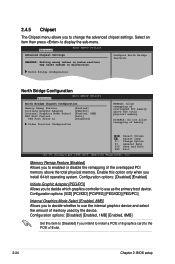
...PEG/PCI] Internal Graphics Mode Select [Enabled, 8MB] Allows you install 64-bit operating system. DISABLE: Do not allow remapping of the overlapped PCI memory above the total physical memory. Select Screen Select Item +- Configuration options: [Disabled] [Enabled] Initiate Graphic Adapter [PEG/PCI] Allows you to change the advanced chipset settings. 2.4.5 Chipset The Chipset menu allows you to decide which graphics controller to use the internal graphics device and select the amount of memory used by the device. Advanced BIOS SETUP UTILITY Advanced Chipset Settings WARMING: Setting...
...PEG/PCI] Internal Graphics Mode Select [Enabled, 8MB] Allows you install 64-bit operating system. DISABLE: Do not allow remapping of the overlapped PCI memory above the total physical memory. Select Screen Select Item +- Configuration options: [Disabled] [Enabled] Initiate Graphic Adapter [PEG/PCI] Allows you to change the advanced chipset settings. 2.4.5 Chipset The Chipset menu allows you to decide which graphics controller to use the internal graphics device and select the amount of memory used by the device. Advanced BIOS SETUP UTILITY Advanced Chipset Settings WARMING: Setting...
User Manual
Page 76
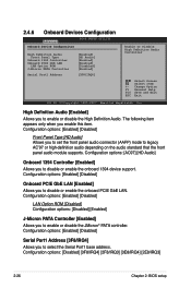
2.4.6 Onboard Devices Configuration Advanced BIOS SETUP UTILITY Onboard Device Configuraiton High Definition Audio Front Panel Type Onboard 1394 Controller Onboard PCIE GbE LAN LAN Option ROM J-Micron PATA Controller [Enabled] [HD Audio] [Enabled] [Enabled] [Disabled] [Enabled] Serial Port1 Address [3F8/IRQ4] Enable or Disable High Definition Audio Controller Select Screen Select Item +- High Definition Audio [Enabled] Allows you to enable or disable the High Definition Audio. Configuration options: [Enabled] [Disabled] Serial Port1 Address [3F8/IRQ4] Allows you to ...
2.4.6 Onboard Devices Configuration Advanced BIOS SETUP UTILITY Onboard Device Configuraiton High Definition Audio Front Panel Type Onboard 1394 Controller Onboard PCIE GbE LAN LAN Option ROM J-Micron PATA Controller [Enabled] [HD Audio] [Enabled] [Enabled] [Disabled] [Enabled] Serial Port1 Address [3F8/IRQ4] Enable or Disable High Definition Audio Controller Select Screen Select Item +- High Definition Audio [Enabled] Allows you to enable or disable the High Definition Audio. Configuration options: [Enabled] [Disabled] Serial Port1 Address [3F8/IRQ4] Allows you to ...
User Manual
Page 78
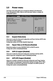
... to display the configuration options. Configuration options: [Disabled] [Enabled] 2.5.3 ACPI 2.0 support [Disabled] Allows you to select the Advanced Configuration and Power Interface (ACPI) state to be used for System Suspend. Change Option F1 General Help F10 Save and Exit ESC Exit v02.58 (C)Copyright 1985-2007, American Megatrends, Inc. 2.5.1 Suspend Mode [Auto] Allows you to select the Advanced Configuration and Power Interface (ACPI) version supported. Configuration options: [Disabled] [Enabled] 2-28 Chapter 2: BIOS setup Main Advanced Power BIOS SETUP UTILITY Boot Tools...
... to display the configuration options. Configuration options: [Disabled] [Enabled] 2.5.3 ACPI 2.0 support [Disabled] Allows you to select the Advanced Configuration and Power Interface (ACPI) state to be used for System Suspend. Change Option F1 General Help F10 Save and Exit ESC Exit v02.58 (C)Copyright 1985-2007, American Megatrends, Inc. 2.5.1 Suspend Mode [Auto] Allows you to select the Advanced Configuration and Power Interface (ACPI) version supported. Configuration options: [Disabled] [Enabled] 2-28 Chapter 2: BIOS setup Main Advanced Power BIOS SETUP UTILITY Boot Tools...
User Manual
Page 92
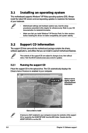
... you install Windows® XP Service Pack 2 or later versions before installing the drivers for updates. 3.2.1 Running the support CD Place the support CD to avail all motherboard features. Refer to your computer, browse the contents of the support CD to change at any time without notice. Use the setup procedures presented in your hardware. • Motherboard settings and hardware options vary. Visit the ASUS website (www.asus.com...
... you install Windows® XP Service Pack 2 or later versions before installing the drivers for updates. 3.2.1 Running the support CD Place the support CD to avail all motherboard features. Refer to your computer, browse the contents of the support CD to change at any time without notice. Use the setup procedures presented in your hardware. • Motherboard settings and hardware options vary. Visit the ASUS website (www.asus.com...


