
P4T533 User Manual
Page 9
...® ATA133 / RAID 0/1 IDE controller Intel® 8256ET ethernet controller (optional) ASUS JumperFree™ mode ASUS POST Reporter™ ASUS EZ Plug™ ASUS EZ Flash ASUS MyLogo2™ ASUS Q-Fan ASUS Multi-language BIOS S/PDIF In/Out Module bundled (optional) Power Loss Restart Adjustable CPU...DRAMs (RDRAMs) up to 2GB. memory. P4T533 specifications summary CPU Socket 478 for 2 additional USB ports CPU/Power/Chassis fan connectors 20-pin/4-pin ATX power connectors IDE LED/Power LED connectors Chassis intrusion and SMBus Front Panel/ SIR connectors GAME/MIDI connector S/PDIF ...
...® ATA133 / RAID 0/1 IDE controller Intel® 8256ET ethernet controller (optional) ASUS JumperFree™ mode ASUS POST Reporter™ ASUS EZ Plug™ ASUS EZ Flash ASUS MyLogo2™ ASUS Q-Fan ASUS Multi-language BIOS S/PDIF In/Out Module bundled (optional) Power Loss Restart Adjustable CPU...DRAMs (RDRAMs) up to 2GB. memory. P4T533 specifications summary CPU Socket 478 for 2 additional USB ports CPU/Power/Chassis fan connectors 20-pin/4-pin ATX power connectors IDE LED/Power LED connectors Chassis intrusion and SMBus Front Panel/ SIR connectors GAME/MIDI connector S/PDIF ...
P4T533 User Manual
Page 24
...) SMARTCON p. 41 Smart Card Reader connector (14-1 pin) (optional) 20) FP_LO_SWL, FP_LO_SWR p. 41 Line-out Selector Jumpers (Two 2 pin) 21) AFPANEL p. 42 ASUS iPanel / Infrared Connector (24-1 pin) 22) LINE_IN p. 43 Front Panel Audio Line In Header (5 pin) 23) AAPANEL p. 43 Front Panel Audio Connector (10-1 pin) 24) SPDIF p. 44 Digital Audio Connector (4-1 pin) (optional) 25) GAME p. 44 Game Header...
...) SMARTCON p. 41 Smart Card Reader connector (14-1 pin) (optional) 20) FP_LO_SWL, FP_LO_SWR p. 41 Line-out Selector Jumpers (Two 2 pin) 21) AFPANEL p. 42 ASUS iPanel / Infrared Connector (24-1 pin) 22) LINE_IN p. 43 Front Panel Audio Line In Header (5 pin) 23) AAPANEL p. 43 Front Panel Audio Connector (10-1 pin) 24) SPDIF p. 44 Digital Audio Connector (4-1 pin) (optional) 25) GAME p. 44 Game Header...
P4T533 User Manual
Page 55
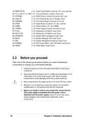
... interface software. P4T533 ® P4T533 Smartcard NC NC SCRREST NC SCRUI SCRRES# SMARTCARD 1 VCC NC SCRFET# SCRCLK NC GND NC2 20. Line-out Selector Jumpers (Two 2 pin FP_LO_SWL, FP_LO_SWR)...ASUS P4T533 motherboard user guide 41 Smart Card Reader Connector (14-1 pin SMARTCON) (Optional) This connector accommodates a Smart Card Reader that enables convenient transactions involving finance, health care, telephony, and travel services using this connector, enable the field: "Onboard Smart Card Reader" in section "4.4.2 I/O Device Configuration." If you connect the Intel Front Panel...
... interface software. P4T533 ® P4T533 Smartcard NC NC SCRREST NC SCRUI SCRRES# SMARTCARD 1 VCC NC SCRFET# SCRCLK NC GND NC2 20. Line-out Selector Jumpers (Two 2 pin FP_LO_SWL, FP_LO_SWR)...ASUS P4T533 motherboard user guide 41 Smart Card Reader Connector (14-1 pin SMARTCON) (Optional) This connector accommodates a Smart Card Reader that enables convenient transactions involving finance, health care, telephony, and travel services using this connector, enable the field: "Onboard Smart Card Reader" in section "4.4.2 I/O Device Configuration." If you connect the Intel Front Panel...
P4T533 User Manual
Page 60
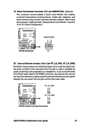
... , and the LED blinks when the system is no incoming data signal. System Management Interrupt Lead (2 pin SMI) This connector permits switching to this 2-pin connector. 32. The LED lights up when the system power is on the BIOS or OS settings. The..." mode: system activity is received. Panel Connector (20 pin PANEL) The following diagram illustrates items 27-33: Keyboard Lock Speaker Power LED Connector +5 V PLED Keylock Ground +5V Ground Ground Speaker +5 V MLED ExtSMI# Ground PWR Ground Reset Ground P4T533 ® P4T533 System Panel Connectors Message LED SMI Lead Reset SW...
... , and the LED blinks when the system is no incoming data signal. System Management Interrupt Lead (2 pin SMI) This connector permits switching to this 2-pin connector. 32. The LED lights up when the system power is on the BIOS or OS settings. The..." mode: system activity is received. Panel Connector (20 pin PANEL) The following diagram illustrates items 27-33: Keyboard Lock Speaker Power LED Connector +5 V PLED Keylock Ground +5V Ground Ground Speaker +5 V MLED ExtSMI# Ground PWR Ground Reset Ground P4T533 ® P4T533 System Panel Connectors Message LED SMI Lead Reset SW...


