Motherboard DIY Troubleshooting Guide
Page 24
30.5cm (12.0in) WARNING PS/2KBMS T: Mouse B: Keyboard USB1.1 T: USB1 B: USB2 KBPWR USBPWR01 OVER_VOLT 24.5cm (9.6in) PWRFAN EZ_PLUG USB2.0 T: USB1 B: USB2 Socket 478 ATX12V TRPWR CPU_FAN DSWF Intel LAN Controller C-Media CMI8738 6CH Audio Controller MODEM AUX CD AAPANEL GAME LINE_IN LO_L LO_R BCS2 BCS1 SPDIF_C LED1 CLCMOS P4T533 ® Super I/O CH_FAN PROMISE PDC20276 ATA133 Controller DSWMUL JEN SMB RAID_SW WOR MODESEL USB2.0 Controller CHASSIS USB_EN USBPWR23 SMARTCARD USB11_23 Speech Controller SMART USB20_12 SPEECH AFPANEL HDLED PANEL 8
30.5cm (12.0in) WARNING PS/2KBMS T: Mouse B: Keyboard USB1.1 T: USB1 B: USB2 KBPWR USBPWR01 OVER_VOLT 24.5cm (9.6in) PWRFAN EZ_PLUG USB2.0 T: USB1 B: USB2 Socket 478 ATX12V TRPWR CPU_FAN DSWF Intel LAN Controller C-Media CMI8738 6CH Audio Controller MODEM AUX CD AAPANEL GAME LINE_IN LO_L LO_R BCS2 BCS1 SPDIF_C LED1 CLCMOS P4T533 ® Super I/O CH_FAN PROMISE PDC20276 ATA133 Controller DSWMUL JEN SMB RAID_SW WOR MODESEL USB2.0 Controller CHASSIS USB_EN USBPWR23 SMARTCARD USB11_23 Speech Controller SMART USB20_12 SPEECH AFPANEL HDLED PANEL 8

Motherboard DIY Troubleshooting Guide
Page 59
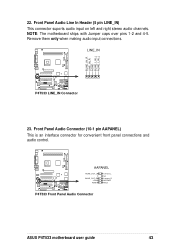
TRPWR Ground TRPWR P4T533 ® P4T533 Power Supply Thermal Connector Keyboard Lock Speaker Power LED Connector +5 V PLED Keylock Ground +5V Ground Ground Speaker +5 V MLED ExtSMI# Ground PWR Ground Reset Ground P4T533 ® P4T533 System Panel Connectors Message LED SMI Lead Reset SW ATX Power Switch* * Requires an ATX power supply. 43
TRPWR Ground TRPWR P4T533 ® P4T533 Power Supply Thermal Connector Keyboard Lock Speaker Power LED Connector +5 V PLED Keylock Ground +5V Ground Ground Speaker +5 V MLED ExtSMI# Ground PWR Ground Reset Ground P4T533 ® P4T533 System Panel Connectors Message LED SMI Lead Reset SW ATX Power Switch* * Requires an ATX power supply. 43

P4T533 User Manual
Page 9
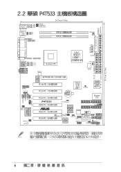
...™ mode ASUS POST Reporter™ ASUS EZ Plug™ ASUS EZ Flash ASUS MyLogo2™ ASUS Q-Fan ASUS Multi-language BIOS S/PDIF In/Out Module bundled (optional) Power Loss Restart Adjustable CPU VCORE AGP warning LED Rear panel I/O 1 x Parallel port 2 x Serial ports 1 x PS/2 keyboard port 1 x PS/2 mouse port 2 x USB 2.0 ports 2 ...(FSB) 533 / 400 MHz Memory 2 x 232-pin 32-bit RIMM4200/3200-compliant Rambus DRAMs (RDRAMs) up to 2GB. P4T533 specifications summary CPU Socket 478 for 2 additional USB ports CPU/Power/Chassis fan connectors 20-pin/4-pin ATX power connectors IDE LED/...
...™ mode ASUS POST Reporter™ ASUS EZ Plug™ ASUS EZ Flash ASUS MyLogo2™ ASUS Q-Fan ASUS Multi-language BIOS S/PDIF In/Out Module bundled (optional) Power Loss Restart Adjustable CPU VCORE AGP warning LED Rear panel I/O 1 x Parallel port 2 x Serial ports 1 x PS/2 keyboard port 1 x PS/2 mouse port 2 x USB 2.0 ports 2 ...(FSB) 533 / 400 MHz Memory 2 x 232-pin 32-bit RIMM4200/3200-compliant Rambus DRAMs (RDRAMs) up to 2GB. P4T533 specifications summary CPU Socket 478 for 2 additional USB ports CPU/Power/Chassis fan connectors 20-pin/4-pin ATX power connectors IDE LED/...
P4T533 User Manual
Page 14
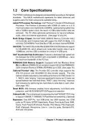
...two USB headers, two COM ports, six PCI slots, S/PDIF Digital Audio, iPanel, Front Audio Panel, SMB, Game, Front Panel/CIR Infrared, Parallel, PS/2 Mouse, PS/2 Keyboard, RJ45 (Optional), Microphone, Line-In / Line... redundancy and stable performance for a total of up to the highest standards. This ASUS motherboard represents the latest advances and supplies users the finest components available today... the ...protection, and HD/SCSI/MO/ZIP/CD/Floppy boot selection. 1.2 Core Specifications The P4T533 motherboard is designed and assembled according to 2GB. (See page 18.) Optional Promise®...
...two USB headers, two COM ports, six PCI slots, S/PDIF Digital Audio, iPanel, Front Audio Panel, SMB, Game, Front Panel/CIR Infrared, Parallel, PS/2 Mouse, PS/2 Keyboard, RJ45 (Optional), Microphone, Line-In / Line... redundancy and stable performance for a total of up to the highest standards. This ASUS motherboard represents the latest advances and supplies users the finest components available today... the ...protection, and HD/SCSI/MO/ZIP/CD/Floppy boot selection. 1.2 Core Specifications The P4T533 motherboard is designed and assembled according to 2GB. (See page 18.) Optional Promise®...

P4T533 User Manual
Page 16
...prevents accidental damage. 1.4 Motherboard Components Before installing the P4T533 motherboard, take time to familiarize yourself with its ... Support 10 2 IDE Connectors (RAID Support 14 Smart Card Connector 16 iPanel / Infrared Connector 17 System Panel Connector 18 USB Headers (USB1.1 20 USB Headers (USB2.0 21 Game Header 31 PS/2 Mouse Connector green... 40 USB 1.1 Connectors (Port 1/2 41 PS/2 Keyboard Connector purple) 42 System Voltage Monitor (integrated in ASUS ASIC 11 Onboard LED 24 Onboard AGP Warning LED 7 Modem Connector 29 RJ45 Connector (optional 35 (Audio Models...
...prevents accidental damage. 1.4 Motherboard Components Before installing the P4T533 motherboard, take time to familiarize yourself with its ... Support 10 2 IDE Connectors (RAID Support 14 Smart Card Connector 16 iPanel / Infrared Connector 17 System Panel Connector 18 USB Headers (USB1.1 20 USB Headers (USB2.0 21 Game Header 31 PS/2 Mouse Connector green... 40 USB 1.1 Connectors (Port 1/2 41 PS/2 Keyboard Connector purple) 42 System Voltage Monitor (integrated in ASUS ASIC 11 Onboard LED 24 Onboard AGP Warning LED 7 Modem Connector 29 RJ45 Connector (optional 35 (Audio Models...
P4T533 User Manual
Page 22
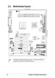
... (MCH) TRPWR CPU_FAN ATX12V DSWF Accelerated Graphics Port AGP PCI1 Intel I/O Controller Hub (ICH2) CLCMOS ASUS ASIC with Hardware Monitor PCI2 PCI3 P4T533 PCI4 ® PCI5 PCI6 CR2032 3V Lithium Cell CMOS Power SEC_RAID Super I/O CH_FAN PRI_RAID JEN SMB ...PROMISE PDC20276 ATA133 Controller DSWMUL RAID_SW WOR MODESEL USB_EN 4Mbit Firmware CHASSIS Hub USBPWR23 SMARTCARD USB2.0 Controller USB11_23 Speech Controller SMART USB20_12 SPEECH AFPANEL HDLED PANEL...
... (MCH) TRPWR CPU_FAN ATX12V DSWF Accelerated Graphics Port AGP PCI1 Intel I/O Controller Hub (ICH2) CLCMOS ASUS ASIC with Hardware Monitor PCI2 PCI3 P4T533 PCI4 ® PCI5 PCI6 CR2032 3V Lithium Cell CMOS Power SEC_RAID Super I/O CH_FAN PRI_RAID JEN SMB ...PROMISE PDC20276 ATA133 Controller DSWMUL RAID_SW WOR MODESEL USB_EN 4Mbit Firmware CHASSIS Hub USBPWR23 SMARTCARD USB2.0 Controller USB11_23 Speech Controller SMART USB20_12 SPEECH AFPANEL HDLED PANEL...
P4T533 User Manual
Page 24
... (14-1 pin) (optional) 20) FP_LO_SWL, FP_LO_SWR p. 41 Line-out Selector Jumpers (Two 2 pin) 21) AFPANEL p. 42 ASUS iPanel / Infrared Connector (24-1 pin) 22) LINE_IN p. 43 Front Panel Audio Line In Header (5 pin) 23) AAPANEL p. 43 Front Panel Audio Connector (10-1 pin) 24) SPDIF p. 44 Digital Audio Connector (4-1 pin) (optional) 25) GAME p. 44 Game...
... (14-1 pin) (optional) 20) FP_LO_SWL, FP_LO_SWR p. 41 Line-out Selector Jumpers (Two 2 pin) 21) AFPANEL p. 42 ASUS iPanel / Infrared Connector (24-1 pin) 22) LINE_IN p. 43 Front Panel Audio Line In Header (5 pin) 23) AAPANEL p. 43 Front Panel Audio Connector (10-1 pin) 24) SPDIF p. 44 Digital Audio Connector (4-1 pin) (optional) 25) GAME p. 44 Game...

P4T533 User Manual
Page 53
USB11_34 USB Power USBP2- USB+5V LDM1 LDP1 GND NC P4T533 1 5 ® USB20_12 6 10 P4T533 USB 2.0 Header USB+5V LDM2 LDP2 GND ASUS P4T533 motherboard user guide 39 USB Header (10-1 pin USB11_34) If the USB port connectors on the rear panel are inadequate, a USB header is available to an open slot in the chassis. USB.... 15. Connect the bundled 2-port USB connector set to this header and mount the USB bracket to support the USB 2.0 standard protocol. USBP2+ GND NC P4T533 ® P4T533 USB 1.1 Header USB Power USBP3- USBP3+ GND 1 5 6 10 16.
USB11_34 USB Power USBP2- USB+5V LDM1 LDP1 GND NC P4T533 1 5 ® USB20_12 6 10 P4T533 USB 2.0 Header USB+5V LDM2 LDP2 GND ASUS P4T533 motherboard user guide 39 USB Header (10-1 pin USB11_34) If the USB port connectors on the rear panel are inadequate, a USB header is available to an open slot in the chassis. USB.... 15. Connect the bundled 2-port USB connector set to this header and mount the USB bracket to support the USB 2.0 standard protocol. USBP2+ GND NC P4T533 ® P4T533 USB 1.1 Header USB Power USBP3- USBP3+ GND 1 5 6 10 16.
P4T533 User Manual
Page 55
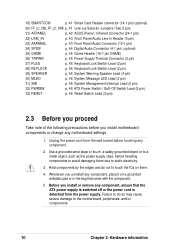
...; P4T533 Smartcard NC NC SCRREST NC SCRUI SCRRES# SMARTCARD 1 VCC NC SCRFET# SCRCLK NC GND NC2 20. If you connect the Intel Front Panel audio cable to the IPANEL connector, (see above) then remove the caps from these jumpers are shorted (jumpers on) to route... controller to the rear panel Line Out jack to permit automatic switching of audio signals between the rear panel Line Out jack and the Intel audio cable. When using a Smart Card user interface software. FP_LO_SWL FP_LO_SWR P4T533 ® P4T533 Internal Line Out Connectors BLOL FLOL BLOR FLOR ASUS P4T533 motherboard user guide 41...
...; P4T533 Smartcard NC NC SCRREST NC SCRUI SCRRES# SMARTCARD 1 VCC NC SCRFET# SCRCLK NC GND NC2 20. If you connect the Intel Front Panel audio cable to the IPANEL connector, (see above) then remove the caps from these jumpers are shorted (jumpers on) to route... controller to the rear panel Line Out jack to permit automatic switching of audio signals between the rear panel Line Out jack and the Intel audio cable. When using a Smart Card user interface software. FP_LO_SWL FP_LO_SWR P4T533 ® P4T533 Internal Line Out Connectors BLOL FLOL BLOR FLOR ASUS P4T533 motherboard user guide 41...
P4T533 User Manual
Page 57
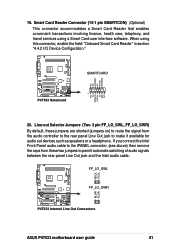
...; AAPANEL BLINE_OUT_L BLINE_OUT_R +5VA AGND Line out_L NC Line out_R MICPWR MIC2 P4T533 Front Panel Audio Connector ASUS P4T533 motherboard user guide 43 LINE_IN P4T533 ® P4T533 LINE_IN Connector 23. Front Panel Audio Connector (10-1 pin AAPANEL) This is an interface connector for convenient front panel connections and audio control. BLINE_IN_R LINE_IN_R AGND BLINE_LIN_L ALINE_LIN_L 22. Remove them...
...; AAPANEL BLINE_OUT_L BLINE_OUT_R +5VA AGND Line out_L NC Line out_R MICPWR MIC2 P4T533 Front Panel Audio Connector ASUS P4T533 motherboard user guide 43 LINE_IN P4T533 ® P4T533 LINE_IN Connector 23. Front Panel Audio Connector (10-1 pin AAPANEL) This is an interface connector for convenient front panel connections and audio control. BLINE_IN_R LINE_IN_R AGND BLINE_LIN_L ALINE_LIN_L 22. Remove them...
P4T533 User Manual
Page 60
... illustrates items 27-33: Keyboard Lock Speaker Power LED Connector +5 V PLED Keylock Ground +5V Ground Ground Speaker +5 V MLED ExtSMI# Ground PWR Ground Reset Ground P4T533 ® P4T533 System Panel Connectors Message LED SMI Lead Reset SW ATX Power Switch* * Requires an ATX power supply. 27. The normal status for rebooting the system without...
... illustrates items 27-33: Keyboard Lock Speaker Power LED Connector +5 V PLED Keylock Ground +5V Ground Ground Speaker +5 V MLED ExtSMI# Ground PWR Ground Reset Ground P4T533 ® P4T533 System Panel Connectors Message LED SMI Lead Reset SW ATX Power Switch* * Requires an ATX power supply. 27. The normal status for rebooting the system without...
P4T533 User Manual
Page 63
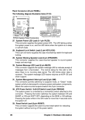
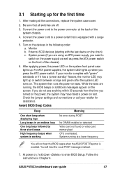
... or call your monitor complies with the last device on the front of the system chassis. 4. You will not hear the BIOS beeps when the ASUS POST Reporter is equipped with a surge protector. 5. Monitor b. External SCSI devices (starting with "green" standards or if it has a "power standby" ... lights up for assistance. Connect the power cord to enter BIOS Setup. ASUS P4T533 motherboard user guide 47 If your retailer for the first time 1. After applying power, the power LED on the system front panel case lights up or switch between orange and green after the system LED...
... or call your monitor complies with the last device on the front of the system chassis. 4. You will not hear the BIOS beeps when the ASUS POST Reporter is equipped with a surge protector. 5. Monitor b. External SCSI devices (starting with "green" standards or if it has a "power standby" ... lights up for assistance. Connect the power cord to enter BIOS Setup. ASUS P4T533 motherboard user guide 47 If your retailer for the first time 1. After applying power, the power LED on the system front panel case lights up or switch between orange and green after the system LED...
P4T533 User Manual
Page 65
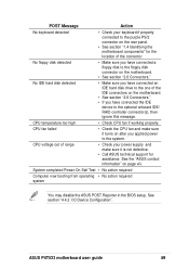
... to the floppy disk connector on page viii. CPU temperature too high • Check CPU fan if working properly. See the "ASUS contact information" on the motherboard. • See section "2.8 Connectors." System completed Power-On Self Test • No action required ... Connectors." • If you have connected a floppy disk to the purple PS/2 connector on the rear panel. • See section "1.4 Identifying the motherboard components" for assistance. ASUS P4T533 motherboard user guide 49 No IDE hard disk detected • Make sure you applied power to the optional ...
... to the floppy disk connector on page viii. CPU temperature too high • Check CPU fan if working properly. See the "ASUS contact information" on the motherboard. • See section "2.8 Connectors." System completed Power-On Self Test • No action required ... Connectors." • If you have connected a floppy disk to the purple PS/2 connector on the rear panel. • See section "1.4 Identifying the motherboard components" for assistance. ASUS P4T533 motherboard user guide 49 No IDE hard disk detected • Make sure you applied power to the optional ...
P4T533 User Manual
Page 92
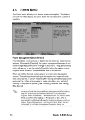
... period of system inactivity. [Min Saving] allows the least power saving as indicated by a battery and power cord icon labeled "Power Management" in the Control Panel. This feature turns off the video display and shuts down the hard disk after a long period of inactivity. The [User Defined] option allows you to...
... period of system inactivity. [Min Saving] allows the least power saving as indicated by a battery and power cord icon labeled "Power Management" in the Control Panel. This feature turns off the video display and shuts down the hard disk after a long period of inactivity. The [User Defined] option allows you to...
P4T533 User Manual
Page 113
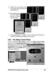
4. ASUS P4T533 motherboard user guide 93 The next step repeats the color matching process to the internet and follow the instructions. 5.6.2 The 3Deep Control Panel Using the Windows Start button, activate the 3Deep Control Panel program from the 3Deep Applications group on the bottom left button to connect to achieve full color... Click on the Main Program menu. Select the color squares which most closely blend and match with the background. 5. The control panel offers access to the Color Wizard tuning program, a Game Gamma setting and a Tweak slider for brightness adjustment.
4. ASUS P4T533 motherboard user guide 93 The next step repeats the color matching process to the internet and follow the instructions. 5.6.2 The 3Deep Control Panel Using the Windows Start button, activate the 3Deep Control Panel program from the 3Deep Applications group on the bottom left button to connect to achieve full color... Click on the Main Program menu. Select the color squares which most closely blend and match with the background. 5. The control panel offers access to the Color Wizard tuning program, a Game Gamma setting and a Tweak slider for brightness adjustment.

P4T533 User Manual
Page 120
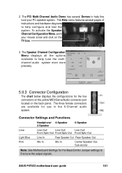
... button: Click on the Main Program menu. LiveUpdate 5.9 Multi-Channel Audio Feature Setup The C-Media PCI Audio Driver and Applications are located on the back panel to display the C-Media Audio Mixer: 2. The Speaker menu offers various configurations for this setup. 5.9.1 The C-Media Audio Mixer 1. The Tools button activates the S/PDIF...
... button: Click on the Main Program menu. LiveUpdate 5.9 Multi-Channel Audio Feature Setup The C-Media PCI Audio Driver and Applications are located on the back panel to display the C-Media Audio Mixer: 2. The Speaker menu offers various configurations for this setup. 5.9.1 The C-Media Audio Mixer 1. The Tools button activates the S/PDIF...
P4T533 User Manual
Page 121
... PC speaker system. The Speaker Channel Configuration Menu displays all the options available to help fine tune your mouse arrow and click on the back panel. Mic Connector Settings and Functions Headphone/ 4-Speaker 2-Speaker 6-Speaker Lime Line Out/ Line Out/ Line Out/ Front Spkr Out Front Spkr Out Front Spkr Out.... The three female connectors Out are available for the line In connectors on the yellow MIDI/Game/Audio connector port located on the TV box. 3. ASUS P4T533 motherboard user guide 101
... PC speaker system. The Speaker Channel Configuration Menu displays all the options available to help fine tune your mouse arrow and click on the back panel. Mic Connector Settings and Functions Headphone/ 4-Speaker 2-Speaker 6-Speaker Lime Line Out/ Line Out/ Line Out/ Front Spkr Out Front Spkr Out Front Spkr Out.... The three female connectors Out are available for the line In connectors on the yellow MIDI/Game/Audio connector port located on the TV box. 3. ASUS P4T533 motherboard user guide 101
P4T533 User Manual
Page 129
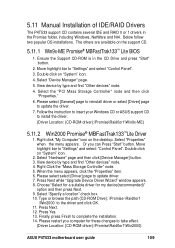
...find "Other devices" node. 4. Please select [General] page to reinstall driver or select [Driver] page to "Settings" and select "Control Panel". 3. Follow the instruction to insert your Windows CD or ASUS support CD to update driver. 7. Right click "My Computer" icon on "System" icon. 4. Select "Properties" when the menu appears. ...OK. 11. Type or browse the path {CD-ROM Drive}: \Promise \Raid0or1 \Win2000 to take effect. (Driver Location: {CD-ROM driver}:\Promise\Raid0or1\Win2000) ASUS P4T533 motherboard user guide 109 Press Next. 12. Please restart you can Press "Start" button.
...find "Other devices" node. 4. Please select [General] page to reinstall driver or select [Driver] page to "Settings" and select "Control Panel". 3. Follow the instruction to insert your Windows CD or ASUS support CD to update driver. 7. Right click "My Computer" icon on "System" icon. 4. Select "Properties" when the menu appears. ...OK. 11. Type or browse the path {CD-ROM Drive}: \Promise \Raid0or1 \Win2000 to take effect. (Driver Location: {CD-ROM driver}:\Promise\Raid0or1\Win2000) ASUS P4T533 motherboard user guide 109 Press Next. 12. Please restart you can Press "Start" button.


