Motherboard DIY Troubleshooting Guide
Page 1
P4SP-MX SE Motherboard
P4SP-MX SE Motherboard

P4SP-MX SE English User Manual E1676a
Page 1
Motherboard P4SP-MX SE User Guide
Motherboard P4SP-MX SE User Guide
P4SP-MX SE English User Manual E1676a
Page 3
Contents Notices v Safety information vi P4SP-MX SE specification summary vii About this guide viii Chapter 1: Product introduction 1.1 Welcome 1-2 1.2 Package contents 1-2 1.3 Special features 1-2 1.3.1 Product highlights 1-2 1.3.2 ASUS unique features 1-4 1.4 Before you proceed 1-5 1.5 Motherboard overview 1-6 1.5.1 Motherboard layout 1-6 1.5.2 Placement direction 1-7 1.5.3 Screw holes 1-7 1.6 Central Processing Unit (CPU 1-8 1.6.1 Overview 1-8 1.6.2 Installing the CPU 1-9 1.7 System memory 1-10 1.7.1 1.7.2 1.7.3 1.7.4 DIMM sockets location 1-10 Memory ...
Contents Notices v Safety information vi P4SP-MX SE specification summary vii About this guide viii Chapter 1: Product introduction 1.1 Welcome 1-2 1.2 Package contents 1-2 1.3 Special features 1-2 1.3.1 Product highlights 1-2 1.3.2 ASUS unique features 1-4 1.4 Before you proceed 1-5 1.5 Motherboard overview 1-6 1.5.1 Motherboard layout 1-6 1.5.2 Placement direction 1-7 1.5.3 Screw holes 1-7 1.6 Central Processing Unit (CPU 1-8 1.6.1 Overview 1-8 1.6.2 Installing the CPU 1-9 1.7 System memory 1-10 1.7.1 1.7.2 1.7.3 1.7.4 DIMM sockets location 1-10 Memory ...
P4SP-MX SE English User Manual E1676a
Page 6
...that the power cables for the devices are unplugged before using an adpater or extension cord. Operation safety • Before installing the motherboard and adding devices on a stable surface. • If you are connected. These devices could interrupt the grounding circuit. •...connectors, slots, sockets and circuitry. • Avoid dust, humidity, and temperature extremes. If possible, disconnect all power cables from the motherboard, ensure that your retailer. If you add a device. • Before connecting or removing signal cables from the existing system before you...
...that the power cables for the devices are unplugged before using an adpater or extension cord. Operation safety • Before installing the motherboard and adding devices on a stable surface. • If you are connected. These devices could interrupt the grounding circuit. •...connectors, slots, sockets and circuitry. • Avoid dust, humidity, and temperature extremes. If possible, disconnect all power cables from the motherboard, ensure that your retailer. If you add a device. • Before connecting or removing signal cables from the existing system before you...
P4SP-MX SE English User Manual E1676a
Page 9
Product introduction Chapter 1 This chapter describes the features of the layout, jumper settings, and connectors. It includes brief descriptions of the motherboard components, and illustrations of the motherboard.
Product introduction Chapter 1 This chapter describes the features of the layout, jumper settings, and connectors. It includes brief descriptions of the motherboard components, and illustrations of the motherboard.
P4SP-MX SE English User Manual E1676a
Page 10
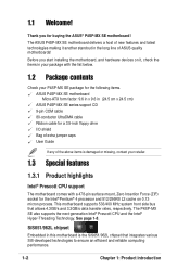
... on it another standout in this motherboard is damaged or missing, contact your P4SP-MX SE package for the following items. ASUS P4SP-MX SE motherboard Micro-ATX form factor: 9.6 in x 9.6 in (24.5 cm x 24.5 cm) ASUS P4SP-MX SE series support CD 9-pin COM cable 80-conductor UltraDMA cable Ribbon cable for buying the ASUS® P4SP-MX SE motherboard! The P4SP-MX SE also supports the next-generation Intel...
... on it another standout in this motherboard is damaged or missing, contact your P4SP-MX SE package for the following items. ASUS P4SP-MX SE motherboard Micro-ATX form factor: 9.6 in x 9.6 in (24.5 cm x 24.5 cm) ASUS P4SP-MX SE series support CD 9-pin COM cable 80-conductor UltraDMA cable Ribbon cable for buying the ASUS® P4SP-MX SE motherboard! The P4SP-MX SE also supports the next-generation Intel...
P4SP-MX SE English User Manual E1676a
Page 11
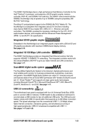
... the Intel® Pentium® 4 processor, and supports a 2D/3D graphic engine, memory controller, AGP 4X, and 533MHz front side bus. ASUS P4SP-MX SE motherboard user guide 1-3 See page 1-17. USB 2.0 connectivity The motherboard rear panel is equipped with the onboard Realtek LAN PHY to connect USB 2.0 devices. Integrated 10/100 Mbps LAN controller The...
... the Intel® Pentium® 4 processor, and supports a 2D/3D graphic engine, memory controller, AGP 4X, and 533MHz front side bus. ASUS P4SP-MX SE motherboard user guide 1-3 See page 1-17. USB 2.0 connectivity The motherboard rear panel is equipped with the onboard Realtek LAN PHY to connect USB 2.0 devices. Integrated 10/100 Mbps LAN controller The...
P4SP-MX SE English User Manual E1676a
Page 12
... BIOS CrashFree BIOS allows users to restore BIOS data from a floppy disk. See page 2-3. 1-4 Chapter 1: Product introduction Unlike other competing vendors' products, ASUS motherboards now enable users to enjoy this protection feature without the need to use a DOS-based utility or boot from a floppy diskette even when BIOS code ...
... BIOS CrashFree BIOS allows users to restore BIOS data from a floppy disk. See page 2-3. 1-4 Chapter 1: Product introduction Unlike other competing vendors' products, ASUS motherboards now enable users to enjoy this protection feature without the need to use a DOS-based utility or boot from a floppy diskette even when BIOS code ...
P4SP-MX SE English User Manual E1676a
Page 13
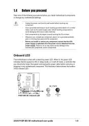
...the system is detached from the wall socket before touching any motherboard component. The illustration below shows the location of the following precautions before you install motherboard components or change any motherboard settings. • Unplug the power cord from the power... lit, the green LED indicates that came with a stand-by the edges to the motherboard, peripherals, and/or components. 1.4 Before you proceed Take note of the onboard LED. ® P4SP-MX SE P4SP-MX SE Onboard LED SB_PWR1 ON Standby Power OFF Powered Off ASUS P4SP-MX SE motherboard user guide 1-5
...the system is detached from the wall socket before touching any motherboard component. The illustration below shows the location of the following precautions before you install motherboard components or change any motherboard settings. • Unplug the power cord from the power... lit, the green LED indicates that came with a stand-by the edges to the motherboard, peripherals, and/or components. 1.4 Before you proceed Take note of the onboard LED. ® P4SP-MX SE P4SP-MX SE Onboard LED SB_PWR1 ON Standby Power OFF Powered Off ASUS P4SP-MX SE motherboard user guide 1-5
P4SP-MX SE English User Manual E1676a
Page 14
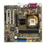
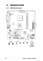
...64/72 bit, 184-pin module) DDR DIMM2 (64/72 bit, 184-pin module) SEC_IDE1 PRI_IDE1 24.4cm (9.6in) 1.5 Motherboard overview 1.5.1 Motherboard layout 24.4cm (9.6in) PS/2KBMS T: Mouse B: Keyboard USBPWR_34 USBPWR_12 SPDIF1 CPU_FAN1 ATX Power Connector PARALLEL PORT VGA1 USB20_12 Bottom:...Accelerated Graphics Port (AGP) 01 23 CR2032 3V Lithium Cell CMOS Power AD1888 CHA_FAN1 SB_PWR1 FP_AUDIO1 PCI Slot 1 ® PCI Slot 2 P4SP-MX SE PCI Slot 3 FLOPPY1 USB_56 SiS962L MuTLOL Media I/0 USBPWR_56 Super I/O CLRTC1 2Mbit Flash BIOS GAME1 COM1 PANEL1 USBPWR_34 USBPWR_12 12 23 +5V...
...64/72 bit, 184-pin module) DDR DIMM2 (64/72 bit, 184-pin module) SEC_IDE1 PRI_IDE1 24.4cm (9.6in) 1.5 Motherboard overview 1.5.1 Motherboard layout 24.4cm (9.6in) PS/2KBMS T: Mouse B: Keyboard USBPWR_34 USBPWR_12 SPDIF1 CPU_FAN1 ATX Power Connector PARALLEL PORT VGA1 USB20_12 Bottom:...Accelerated Graphics Port (AGP) 01 23 CR2032 3V Lithium Cell CMOS Power AD1888 CHA_FAN1 SB_PWR1 FP_AUDIO1 PCI Slot 1 ® PCI Slot 2 P4SP-MX SE PCI Slot 3 FLOPPY1 USB_56 SiS962L MuTLOL Media I/0 USBPWR_56 Super I/O CLRTC1 2Mbit Flash BIOS GAME1 COM1 PANEL1 USBPWR_34 USBPWR_12 12 23 +5V...
P4SP-MX SE English User Manual E1676a
Page 15
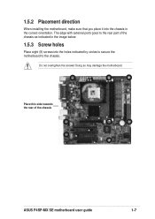
The edge with external ports goes to the chassis. Do not overtighten the screws! Place this side towards the rear of the chassis as indicated in the correct orientation. 1.5.2 Placement direction When installing the motherboard, make sure that you place it into the chassis in the image below. 1.5.3 Screw holes Place eight (8) screws into the holes indicated by circles to secure the motherboard to the rear part of the chassis ASUS P4SP-MX SE motherboard user guide 1-7 Doing so may damage the motherboard.
The edge with external ports goes to the chassis. Do not overtighten the screws! Place this side towards the rear of the chassis as indicated in the correct orientation. 1.5.2 Placement direction When installing the motherboard, make sure that you place it into the chassis in the image below. 1.5.3 Screw holes Place eight (8) screws into the holes indicated by circles to secure the motherboard to the rear part of the chassis ASUS P4SP-MX SE motherboard user guide 1-7 Doing so may damage the motherboard.
P4SP-MX SE English User Manual E1676a
Page 17
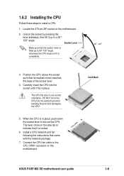
...cable to indicate that the socket lever is in one correct orientation. The lever clicks on the side tab to the CPU_FAN1 connector on the motherboard. 2. The CPU fits only in place, push down the socket lever to install a CPU. 1. When the CPU is lifted up to... 1.6.2 Installing the CPU Follow these steps to secure the CPU. Socket Lever Make sure that it fits in completely. 90 - 100 3. Gold Mark ASUS P4SP-MX SE motherboard user guide 1-9 Position the CPU above the socket such that came with the heatsink package. 7. Carefully insert the CPU into the socket to a 90...
...cable to indicate that the socket lever is in one correct orientation. The lever clicks on the side tab to the CPU_FAN1 connector on the motherboard. 2. The CPU fits only in place, push down the socket lever to install a CPU. 1. When the CPU is lifted up to... 1.6.2 Installing the CPU Follow these steps to secure the CPU. Socket Lever Make sure that it fits in completely. 90 - 100 3. Gold Mark ASUS P4SP-MX SE motherboard user guide 1-9 Position the CPU above the socket such that came with the heatsink package. 7. Carefully insert the CPU into the socket to a 90...
P4SP-MX SE English User Manual E1676a
Page 18
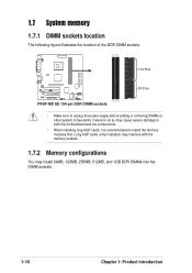
1.7 System memory 1.7.1 DIMM sockets location The following figure illustrates the location of the DDR DIMM sockets. 104 Pins ® P4SP-MX SE P4SP-MX SE 184-pin DDR DIMM sockets 80 Pins • Make sure to install the memory modules first. Failure to do so may ...Product introduction Long AGP cards, when installed, may interfere with the memory sockets. 1.7.2 Memory configurations You may cause severe damage to both the motherboard and the components. • When installing long AGP cards, it is recommended to unplug the power supply before adding or removing DIMMs or other...
1.7 System memory 1.7.1 DIMM sockets location The following figure illustrates the location of the DDR DIMM sockets. 104 Pins ® P4SP-MX SE P4SP-MX SE 184-pin DDR DIMM sockets 80 Pins • Make sure to install the memory modules first. Failure to do so may ...Product introduction Long AGP cards, when installed, may interfere with the memory sockets. 1.7.2 Memory configurations You may cause severe damage to both the motherboard and the components. • When installing long AGP cards, it is recommended to unplug the power supply before adding or removing DIMMs or other...
P4SP-MX SE English User Manual E1676a
Page 19
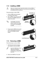
... when it fits in place and the DIMM is keyed with a notch so that the notch on the DIMM matches the break on the socket. ASUS P4SP-MX SE motherboard user guide 1-11 Remove the DIMM from the socket. 1.7.3 Installing a DIMM Make sure to remove a DIMM. 1. Align a DIMM on the socket such that it flips...
... when it fits in place and the DIMM is keyed with a notch so that the notch on the DIMM matches the break on the socket. ASUS P4SP-MX SE motherboard user guide 1-11 Remove the DIMM from the socket. 1.7.3 Installing a DIMM Make sure to remove a DIMM. 1. Align a DIMM on the socket such that it flips...
P4SP-MX SE English User Manual E1676a
Page 20
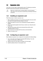
...the expansion card, read the documentation that they support. 1.8 Expansion slots In the future, you may cause you physical injury and damage motherboard components. 1.8.1 Installing an expansion card Follow these steps to unplug the power cord before adding or removing expansion cards. Refer to the ...tables on the slot. 5. Install the software drivers for later use . Remove the system unit cover (if your motherboard is completely seated on the next page. 3. Keep the screw for the expansion card. 1-12 Chapter 1: Product introduction The following sub-...
...the expansion card, read the documentation that they support. 1.8 Expansion slots In the future, you may cause you physical injury and damage motherboard components. 1.8.1 Installing an expansion card Follow these steps to unplug the power cord before adding or removing expansion cards. Refer to the ...tables on the slot. 5. Install the software drivers for later use . Remove the system unit cover (if your motherboard is completely seated on the next page. 3. Keep the screw for the expansion card. 1-12 Chapter 1: Product introduction The following sub-...
P4SP-MX SE English User Manual E1676a
Page 21
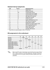
... 14* 9 Primary IDE Channel 15* 10 Secondary IDE Channel * These IRQs are usually available for this motherboard ABCDE PCI slot 1 - used -- -- -- used - - Onboard LAN - - - shared - - GH used Onboard USB controller 2 - - - - - shared - - used - - - - - Onboard VGA shared - - - - ASUS P4SP-MX SE motherboard user guide 1-13 Onboard USB 2.0 controller - - - - - Otherwise, conflicts will arise between the two PCI groups, making...
... 14* 9 Primary IDE Channel 15* 10 Secondary IDE Channel * These IRQs are usually available for this motherboard ABCDE PCI slot 1 - used -- -- -- used - - Onboard LAN - - - shared - - GH used Onboard USB controller 2 - - - - - shared - - used - - - - - Onboard VGA shared - - - - ASUS P4SP-MX SE motherboard user guide 1-13 Onboard USB 2.0 controller - - - - - Otherwise, conflicts will arise between the two PCI groups, making...
P4SP-MX SE English User Manual E1676a
Page 22
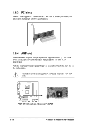
.... Install only +1.5V AGP cards. ® P4SP-MX SE P4SP-MX SE Accelerated Graphics Port (AGP ) 1-14 Chapter 1: Product introduction 1.8.3 PCI slots The PCI slots support PCI cards such as a LAN card, SCSI card, USB card, and other cards that comply with +1.5V specification. Note the notches on the motherboard. When you buy an AGP card, make...
.... Install only +1.5V AGP cards. ® P4SP-MX SE P4SP-MX SE Accelerated Graphics Port (AGP ) 1-14 Chapter 1: Product introduction 1.8.3 PCI slots The PCI slots support PCI cards such as a LAN card, SCSI card, USB card, and other cards that comply with +1.5V specification. Note the notches on the motherboard. When you buy an AGP card, make...

P4SP-MX SE English User Manual E1676a
Page 23
... data in CMOS. Keep the cap on CLRTC1 jumper default position. Removing the cap will cause system boot failure! ® P4SP-MX SE CLRTC1 12 23 Normal (Default) Clear CMOS P4SP-MX SE Clear RTC RAM setting ASUS P4SP-MX SE motherboard user guide 1-15 Move the jumper cap from pins 1-2 (default) to clear the Real Time Clock (RTC) RAM in...
... data in CMOS. Keep the cap on CLRTC1 jumper default position. Removing the cap will cause system boot failure! ® P4SP-MX SE CLRTC1 12 23 Normal (Default) Clear CMOS P4SP-MX SE Clear RTC RAM setting ASUS P4SP-MX SE motherboard user guide 1-15 Move the jumper cap from pins 1-2 (default) to clear the Real Time Clock (RTC) RAM in...
P4SP-MX SE English User Manual E1676a
Page 25
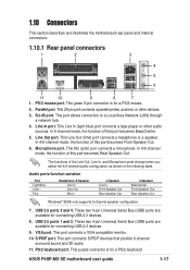
... VGA compatible monitor. 10. This port connects S/PDIF devices that provide 6-channel surround sound and 3D audio. 11. ASUS P4SP-MX SE motherboard user guide 1-17 Parallel port. Line In port. The functions of this port becomes Rear Speaker Out. Audio ports ...USB 2.0 devices. 9. This purple connector is for a PS/2 keyboard. This Mic (pink) port connects a microphone. 1.10 Connectors This section describes and illustrates the motherboard rear panel and internal connectors. 1.10.1 Rear panel connectors 1 2 3 4 5 6 11 10 9 8 7 1. USB 2.0 ports 3 and 4. PS/2...
... VGA compatible monitor. 10. This port connects S/PDIF devices that provide 6-channel surround sound and 3D audio. 11. ASUS P4SP-MX SE motherboard user guide 1-17 Parallel port. Line In port. The functions of this port becomes Rear Speaker Out. Audio ports ...USB 2.0 devices. 9. This purple connector is for a PS/2 keyboard. This Mic (pink) port connects a microphone. 1.10 Connectors This section describes and illustrates the motherboard rear panel and internal connectors. 1.10.1 Rear panel connectors 1 2 3 4 5 6 11 10 9 8 7 1. USB 2.0 ports 3 and 4. PS/2...
P4SP-MX SE English User Manual E1676a
Page 26
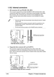
...(40-1 pin PRI_IDE1, SEC_IDE1) This connector supports the provided UltraDMA133 IDE hard disk ribbon cable. After connecting one end to the motherboard, connect the other end to the floppy drive. (Pin 5 is removed to PIN 1. Connect the cable's blue connector to ... Floppy disk drive connector (34-1 pin FLOPPY1) This connector supports the provided floppy drive ribbon cable. P4SP-MX SE Floppy disk drive connector 1-18 Chapter 1: Product introduction FLOPPY1 ® P4SP-MX SE PIN 1 NOTE: Orient the red markings on each IDE connector is removed to PIN 1 SEC_IDE1 PRI_IDE1 ...
...(40-1 pin PRI_IDE1, SEC_IDE1) This connector supports the provided UltraDMA133 IDE hard disk ribbon cable. After connecting one end to the motherboard, connect the other end to the floppy drive. (Pin 5 is removed to PIN 1. Connect the cable's blue connector to ... Floppy disk drive connector (34-1 pin FLOPPY1) This connector supports the provided floppy drive ribbon cable. P4SP-MX SE Floppy disk drive connector 1-18 Chapter 1: Product introduction FLOPPY1 ® P4SP-MX SE PIN 1 NOTE: Orient the red markings on each IDE connector is removed to PIN 1 SEC_IDE1 PRI_IDE1 ...


