P4sp-mx(se)/l - Asus P4SP MX SE
P4sp-mx(se)/l
Related Manual Pages


Related Videos

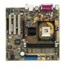
Motherboard Asus P4SP-MX SE
Duration: :35
Total Views: 388
Duration: :35
Total Views: 388
Similar Questions

M2n Mx Se Motherboard Support Windows 10 ?
M2N MX SE motherboard support windows 10 ?
M2N MX SE motherboard support windows 10 ?
(Posted by mrvijay6335 7 months ago)

Would Any New Geforce Graphics Cards Fit Into My Old Asus P5ld2-vm Se Motherbord
fit into my old asus p5ld2-vm se motherbord?
fit into my old asus p5ld2-vm se motherbord?
(Posted by mornevolschenk 11 years ago)

I Need Audio Card P4 Ql Se
i need audio card p5 ql se for pc all pro
i need audio card p5 ql se for pc all pro
(Posted by wwwrasg999 11 years ago)
Related Terms
The following terms were also used when searching for P4sp-mx(se)/l - Asus P4SP MX SE:- asus p4sp mx se
- asus p4sp mx se audio
- asus p4sp mx se audio driver
- asus p4sp mx se audio driver download
- asus p4sp mx se cpu support
- asus p4sp mx se driver
- asus p4sp mx se driver download
- asus p4sp mx se drivers
- asus p4sp mx se lan driver
- asus p4sp mx se manual
- asus p4sp mx se motherboard
- asus p4sp mx se motherboard drivers
- asus p4sp mx se vga driver download
- asus p4sp mx se video driver
- asus p4sp mx se xp driver
- asus p4sp mx serial
- asus p4sp-mx se
- asus p4sp-mx se acpi
- asus p4sp-mx se audio
- asus p4sp-mx se audio driver
- asus p4sp-mx se bios
- asus p4sp-mx se bios update
- asus p4sp-mx se download
- asus p4sp-mx se driver
- asus p4sp-mx se driver download
- asus p4sp-mx se driver download free
- asus p4sp-mx se driver windows 7
- asus p4sp-mx se drivers
- asus p4sp-mx se drivers windows 7
- asus p4sp-mx se manual
- asus p4sp-mx se ram slot
- asus p4sp-mx se sound driver
- asus p4sp-mx se user manual
- asus p4sp-mx se vga driver
- asus p4sp-mx se windows 7
- asus p4sp-mx ses driver
- asus p4sp-mx sound driver
- asus p4spmxse
- asustek p4spmxse
- drive p4sp mx se
- drive p4sp-mx se
- driver asus p4sp mx se
- driver asus p4sp-mx se
- driver p4sp mx se
- driver p4sp-mx se
- driver sound asus p4sp-mx se
- driver sound p4sp-mx se
- drivers p4sp mx se
- manual asus p4sp-mx se
- manual p4sp-mx se
- mother asus p4sp-mx se
- mother p4sp-mx se
- motherboard asus p4sp mx se
- motherboard asus p4sp-mx se
- motherboard p4sp mx se
- motherboard p4sp-mx se
- p4sp mx se
- p4sp mx se asus
- p4sp mx se asus driver
- p4sp mx se audio
- p4sp mx se audio driver
- p4sp mx se audio driver download
- p4sp mx se audio driver xp
- p4sp mx se audio drivers download
- p4sp mx se bios
- p4sp mx se cpu support
- p4sp mx se driver
- p4sp mx se driver download
- p4sp mx se drivers
- p4sp mx se free download
- p4sp mx se free driver
- p4sp mx se lan driver
- p4sp mx se manual
- p4sp mx se motherboard
- p4sp mx se motherboard drivers
- p4sp mx se sound driver
- p4sp mx se vga driver download
- p4sp mx se video driver
- p4sp mx se xp driver
- p4sp mx serial
- p4sp-mx drivers
- p4sp-mx drivers for xp
- p4sp-mx se
- p4sp-mx se acpi
- p4sp-mx se asus
- p4sp-mx se audio
- p4sp-mx se audio driver
- p4sp-mx se bios
- p4sp-mx se bios download
- p4sp-mx se bios update
- p4sp-mx se cpu
- p4sp-mx se download
- p4sp-mx se download driver
- p4sp-mx se driver
- p4sp-mx se driver download
- p4sp-mx se driver download free
- p4sp-mx se driver soundmax
- p4sp-mx se driver windows 7
- p4sp-mx se drivers
- p4sp-mx se drivers download
- p4sp-mx se drivers windows 7
- p4sp-mx se lan driver
- p4sp-mx se manual
- p4sp-mx se memory
- p4sp-mx se motherboard
- p4sp-mx se ram slot
- p4sp-mx se sound driver
- p4sp-mx se soundmax
- p4sp-mx se user manual
- p4sp-mx se vga
- p4sp-mx se vga driver
- p4sp-mx se windows 7
- p4sp-mx ses driver
- p4sp-mx sound driver
- p4sp-mx(se)/l
- p4spmxse
- p4spmxse asus
- p4spmxse driver
- p4spmxse driver video
- placa asus p4sp-mx se
- placa mae asus p4sp-mx se
- placa mae p4sp-mx se
- placa p4sp-mx se