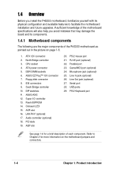
Motherboard DIY Troubleshooting Guide
Page 43
P4S333 ® P4S333 IDE Connectors IDE2 IDE1 NOTE: Orient the red markings (usually zigzag) on the IDE ribbon cable to PIN 1. PIN 1 2-23
Motherboard DIY Troubleshooting Guide
Page 44
FLOPPY NOTE: Orient the red markings on the floppy ribbon cable to PIN 1. P4S333 ® PIN 1 P4S333 Floppy Disk Drive Connector +5VSB_MB Chassis Signal GND CHASSIS P4S333 ® P4S333 Chassis Alarm Lead 2-24
Motherboard DIY Troubleshooting Guide
Page 45
PWRFAN1 GND +12V Rotation CPUFAN1 GND +12V Rotation P4S333 ® CHAFAN1 P4S333 12-Volt Fan Connectors Rotation +12V GND 2-25
Motherboard DIY Troubleshooting Guide
Page 46
2-26 P4S333 ® ATXPWR Pin 1 P4S333 ATX & Auxiliary Power Connectors +12V DC +12V DC ATX12V +12.0VDC +5VSB PWR_OK COM +5.0VDC COM +5.0VDC COM +3.3VDC +3.3VDC +5.0VDC +5.0VDC -5.0VDC COM COM COM PS_ON# COM -12.0VDC +3.3VDC COM Pin 1 COM AUX12V +12V GND GND +5V
Motherboard DIY Troubleshooting Guide
Page 47
USB Power 6 10 USB1 USB2 USB Power GND USBP5+ USBP5- 2-27 P4S333 SMBus Connector P4S333 ® FLOATING SMBCLK Ground SMBDATA +3V SMB 1 P4S333 Front Panel USB Headers P4S333 ® 1 5 OC2# GND USBP4+ USBP4- USB Power GND USBP3+ USBP3- USB Power 6 10 15 OC1# GND USBP2+ USBP2-
Motherboard DIY Troubleshooting Guide
Page 48
AUX1 (White) Left Audio Channel Ground Ground Right Audio Channel CD1 (Black) P4S333 ® P4S333 Internal Audio Connectors Right Audio Channel Ground Ground Left Audio Channel MODEM Modem-In Ground Ground Modem-Out 2-28 IAPANEL1 1 P4S333 ® P4S333 Audio Panel Connector LineOut_RL LineOut_RR NC AGND LineOut_FL NC LineOut_FR MICPWR MIC
Motherboard DIY Troubleshooting Guide
Page 50
ALINE_LIN_R BLINE_LIN_R GND LINE_IN_L BLINE_IN_L ALIN1 1 P4S333 ® P4S333 LINE_IN Connector P4S333 ® MS1 SD1 1 1 SDALED SDAPWCTL# SDACLK SDA5 SDA4 SDA3 MSDA2 +3V MSDA1 GND SDBLED SDBPWCTL# SDBCLK SDB5 SDB4 SDB3 SDB2 +3V SDB1 GND P4S333 SD MS Connectors 2-30
Motherboard DIY Troubleshooting Guide
Page 51
P4S333 ® P4S333 Smartcard SCRRES# SCIO NC SCRREST NC NC NC2 GND NC SCRCLK SCPWR NC VCC SMARTCON1 1 IR 1 P4S333 ® P4S333 Infrared Module Connector +5V IRRX GND IRTX Front View Back View IRTX +5V GND (NC) IRRX 2-31
Motherboard DIY Troubleshooting Guide
Page 52
PWRTMP P4S333 Power Supply Thermal Sensor ® P4S333 Thermal Sensor Connector COM2 PIN 1 P4S333 ® P4S333 Serial COM2 Bracket 2-32
Motherboard DIY Troubleshooting Guide
Page 53
P4S333 ® P4S333 SIRQ1 Connector SIRQ1 SERIRQ GND Power LED Speaker Connector +5 V PLED +5V Ground Ground Speaker +5 V MLED ExtSMI# Ground PWR Ground Reset Ground Reset SW P4S333 Message LED ® ATX Power SMI Lead Switch* * Requires an ATX power supply. P4S333 System Panel Connectors • • 2-33
P4S333 English Manual
Page 4
Safeguards Contents 2.6.4 AGP slot 2-15 2.6.5 ACR slot 2-16 2.7 Switches and jumpers 2-17 2.8 Connectors 2-22 Chapter 3: Powering up 3-1 3.1 Starting up for the first time 3-1 3.2 Vocal POST Messages 3-2 3.3 Powering off the computer 3-4 Chapter 4: BIOS setup 4-1 4.1 Managing and updating your BIOS 4-1 4.1.1 ...
P4S333 English Manual
Page 7
... or extension cord. vii Contact a qualified service technician or your dealer immediately. • To avoid short circuits, keep paper clips, screws, and staples away from connectors, slots, sockets and circuitry. • Avoid dust, humidity, and temperature extremes.
P4S333 English Manual
Page 8
... contains the information you have to change system settings through the BIOS Setup menus. It includes description of the switches, jumpers, and connectors on the motherboard. • Chapter 3: Powering up This chapter describes the power up sequence and gives information on the BIOS beep ... CD that comes with the motherboard package. • Glossary This part lists the technical terms that you need when installing the ASUS P4S333 motherboard. viii Detailed descriptions of the BIOS parameters are also provided. • Chapter 5: Software support This chapter describes the contents...
P4S333 English Manual
Page 14
... your existing power supply rather than buying a new ATX 12V power supply. The ASUS EZ Plug™ is a 4-pin auxiliary +12V connector mounted on audio models only) On audio models, a digital audio connector is onboard to accommodate the Sony/Philips Digital Interface (S/PDIF) Out module, which ...known as P4, via a 478-pin surface mount ZIF socket. DDR memory support Employing the Double Data Rate (DDR) memory technology, the P4S333 motherboard supports up to deliver the required bandwidth for audio, video, and Internet applications. Onboard LAN (on audio models only) A C-Media ...
P4S333 English Manual
Page 15
..., and Memory Stick (MS). ASUS P4S333 motherboard user guide 1-3 Refer to provide friendly voice messages and alerts during the Power-On SelfTests (POST). The bundled Winbond Voice Editor software allows you of the system boot status and causes of system status. Special Card Reader support The P4S333 includes special connectors that support optional readers...
P4S333 English Manual
Page 16
... knowledge of the motherboard specifications will also help you install the P4S333 motherboard, familiarize yourself with its components. 1.4.1 Motherboard components The following are the major components of each component. Floppy disk connector 8. Super I/O controller 13. Flash EEPROM 14. ACR slot 16...features to Chapter 2 for a brief description of the P4S333 motherboard as pointed out in the picture on the motherboard jumpers and connectors. 1-4 Chapter 1: Product introduction ATX 12V connector 2. DIP switches 11. ASUS ASIC 12. PS/2 mouse port 21. Parallel port 23...
P4S333 English Manual
Page 18
... provide sufficient power to 3GB system memory using unbuffered non-ECC PC2100/ 1600 DDR DIMMs, 2GB using PC2700. 6 ASUS EZ Plug™ Auxiliary +12V connector. A 478-pin surface mount, Zero Insertion Force (ZIF) socket called mPGA478 B. This socket accommodates the Intel® Pentium® 4... Host controllers, IDE Master/Slave controllers, and the MuTIOL Connect to set the CPU external frequency. 11 ASUS ASIC. The power supply must have an ATX +12V power supply. This connector accommodates the provided ribbon cable for the Intel® Pentium® 4 processor, a memory controller, an...
P4S333 English Manual
Page 19
...used Super I /O controller. This LED acts as a reminder to a Local Area Network (LAN) through a network hub. (on audio models only) ASUS P4S333 motherboard user guide 1-7 This onboard LED lights up if there is for a PS/2 mouse. 21 RJ-45 port. The chipset supports a high-performance...the South Bridge controller to fully support 10BASE-T/100BASE-TX Fast Ethernet networking protocols. (on audio models only) 18 PCI slots. This connector supports a joystick or a game pad for playing games, and MIDI devices for communication and audio subsystems. The slot supports modem, audio...
P4S333 English Manual
Page 20
.... This 9-pin COM1 port is also available for pointing devices or other audio sources. (on audio models only) 25 Line In jack. This purple 6-pin connector is for connecting USB devices such as a mouse and PDA. 24 Microphone jack. These two 4-pin Universal Serial Bus (USB) ports are available for a PS...
P4S333 English Manual
Page 21
Hardware information It includes details on the switches, jumpers, and connectors on the motherboard. Chapter 2 This chapter describes the hardware setup procedures that you have to perform when installing system components.