User Manual
Page 4
Safeguards Contents 2.6.4 AGP slot 2-15 2.6.5 ACR slot 2-16 2.7 Switches and jumpers 2-17 2.8 Connectors 2-22 Chapter 3: Powering up 3-1 3.1 Starting up for the first time 3-1 3.2 Vocal POST Messages 3-2 3.3 Powering off the computer 3-4 Chapter 4: BIOS setup 4-1 4.1 Managing and updating your BIOS 4-1 4.1.1 ...
Safeguards Contents 2.6.4 AGP slot 2-15 2.6.5 ACR slot 2-16 2.7 Switches and jumpers 2-17 2.8 Connectors 2-22 Chapter 3: Powering up 3-1 3.1 Starting up for the first time 3-1 3.2 Vocal POST Messages 3-2 3.3 Powering off the computer 3-4 Chapter 4: BIOS setup 4-1 4.1 Managing and updating your BIOS 4-1 4.1.1 ...

User Manual
Page 7
... technician or your retailer. Contact a qualified service technician or your dealer immediately. • To avoid short circuits, keep paper clips, screws, and staples away from connectors, slots, sockets and circuitry. • Avoid dust, humidity, and temperature extremes.
... technician or your retailer. Contact a qualified service technician or your dealer immediately. • To avoid short circuits, keep paper clips, screws, and staples away from connectors, slots, sockets and circuitry. • Avoid dust, humidity, and temperature extremes.
User Manual
Page 8
It includes description of the switches, jumpers, and connectors on the motherboard. • Chapter 3: Powering up This chapter describes the power up sequence and gives information on the BIOS beep codes. • Chapter 4: BIOS ... the motherboard and the new technology it supports. • Chapter 2: Hardware information This chapter lists the hardware setup procedures that you need when installing the ASUS P4S333 motherboard. About this guide This user guide contains the information you may encounter when reading this document. • Index This part contains an alphabetical list...
It includes description of the switches, jumpers, and connectors on the motherboard. • Chapter 3: Powering up This chapter describes the power up sequence and gives information on the BIOS beep codes. • Chapter 4: BIOS ... the motherboard and the new technology it supports. • Chapter 2: Hardware information This chapter lists the hardware setup procedures that you need when installing the ASUS P4S333 motherboard. About this guide This user guide contains the information you may encounter when reading this document. • Index This part contains an alphabetical list...
User Manual
Page 14
...(on the motherboard that connects a regular 4-pin device power connector from the power supply. This connector is onboard to support 10BASE-T/100BASE-TX Fast Ethernet networking. ASUS EZ Plug™ This patented ASUS technology lets you use your existing power supply rather than buying...Refer to provide the additional power required by the P4 CPU. The ASUS EZ Plug™ is onboard to a speedy 2.4+GHz frequency. 1.3 Special features 1.3.1 Product highlights Latest processor technology The P4S333 motherboard supports the latest Intel Pentium 4 478/ Northwood Processor, also known...
...(on the motherboard that connects a regular 4-pin device power connector from the power supply. This connector is onboard to support 10BASE-T/100BASE-TX Fast Ethernet networking. ASUS EZ Plug™ This patented ASUS technology lets you use your existing power supply rather than buying...Refer to provide the additional power required by the P4 CPU. The ASUS EZ Plug™ is onboard to a speedy 2.4+GHz frequency. 1.3 Special features 1.3.1 Product highlights Latest processor technology The P4S333 motherboard supports the latest Intel Pentium 4 478/ Northwood Processor, also known...
User Manual
Page 15
... The P4S333 includes special connectors that support optional readers for fine-tuning system bus frequency from 100MHz up to 166MHz at 1MHz increments • optimized system performance through the sophisticated SD and MS devices. 1.3.2 Value-added solutions Overclocking The P4S333 overclocking ...in optimization mode • adjustable CPU VCORE and DDR memory voltage ASUS iPanel support The motherboard supports the ASUS iPanel to customize the voice messages, and provides multi-language support. ASUS P4S333 motherboard user guide 1-3 Refer to provide friendly voice messages and ...
... The P4S333 includes special connectors that support optional readers for fine-tuning system bus frequency from 100MHz up to 166MHz at 1MHz increments • optimized system performance through the sophisticated SD and MS devices. 1.3.2 Value-added solutions Overclocking The P4S333 overclocking ...in optimization mode • adjustable CPU VCORE and DDR memory voltage ASUS iPanel support The motherboard supports the ASUS iPanel to customize the voice messages, and provides multi-language support. ASUS P4S333 motherboard user guide 1-3 Refer to provide friendly voice messages and ...
User Manual
Page 16
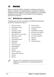
... physical configuration and available features to Chapter 2 for a brief description of the P4S333 motherboard as pointed out in the picture on the motherboard jumpers and connectors. 1-4 Chapter 1: Product introduction CPU socket 4. Floppy disk connector 8. Onboard LED 15. ASUS EZ Plug™ 12V connector 7. IDE connectors 9. RJ-45 port (optional) 22. PS/2 Keyboard port See page 1-6 for...
... physical configuration and available features to Chapter 2 for a brief description of the P4S333 motherboard as pointed out in the picture on the motherboard jumpers and connectors. 1-4 Chapter 1: Product introduction CPU socket 4. Floppy disk connector 8. Onboard LED 15. ASUS EZ Plug™ 12V connector 7. IDE connectors 9. RJ-45 port (optional) 22. PS/2 Keyboard port See page 1-6 for...
User Manual
Page 18
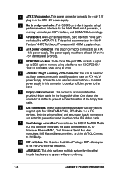
...3GB system memory using unbuffered non-ECC PC2100/ 1600 DDR DIMMs, 2GB using PC2700. 6 ASUS EZ Plug™ Auxiliary +12V connector. Both the primary (blue) and secondary (black) connectors are slotted to prevent incorrect insertion of the IDE ribbon cable. 9 South bridge controller....controllers, and the MuTIOL Connect to an ATX +12V power supply. This ASUS patented auxiliary power connector is slotted to prevent incorrect insertion of the floppy disk cable. 8 IDE connectors. Connect a 4-pin device connector from the ATX 12V power supply. 2 North bridge controller. This chip...
...3GB system memory using unbuffered non-ECC PC2100/ 1600 DDR DIMMs, 2GB using PC2700. 6 ASUS EZ Plug™ Auxiliary +12V connector. Both the primary (blue) and secondary (black) connectors are slotted to prevent incorrect insertion of the IDE ribbon cable. 9 South bridge controller....controllers, and the MuTIOL Connect to an ATX +12V power supply. This ASUS patented auxiliary power connector is slotted to prevent incorrect insertion of the floppy disk cable. 8 IDE connectors. Connect a 4-pin device connector from the ATX 12V power supply. 2 North bridge controller. This chip...
User Manual
Page 19
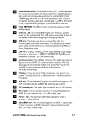
...Flash ROM interface. 13 Flash EEPROM. This ICS 1893Y LAN PHY works with 133MB/s maximum throughput. 19 AGP slot. This green 6-pin connector is a standby power on LAN models only) 22 Parallel port. The chipset supports a high-performance floppy disk controller for a PS/2 ...48K formats) professional digital audio interface. (on audio models only) ASUS P4S333 motherboard user guide 1-7 This 25-pin port connects a parallel printer, a scanner, or other devices. 23 Game/MIDI port. 12 Super I /O functionality. This connector supports a joystick or a game pad for playing games, and ...
...Flash ROM interface. 13 Flash EEPROM. This ICS 1893Y LAN PHY works with 133MB/s maximum throughput. 19 AGP slot. This green 6-pin connector is a standby power on LAN models only) 22 Parallel port. The chipset supports a high-performance floppy disk controller for a PS/2 ...48K formats) professional digital audio interface. (on audio models only) ASUS P4S333 motherboard user guide 1-7 This 25-pin port connects a parallel printer, a scanner, or other devices. 23 Game/MIDI port. 12 Super I /O functionality. This connector supports a joystick or a game pad for playing games, and ...
User Manual
Page 20
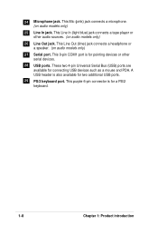
... is for connecting USB devices such as a mouse and PDA. A USB header is for two additional USB ports. 29 PS/2 keyboard port. This purple 6-pin connector is also available for a PS/2 keyboard. 1-8 Chapter 1: Product introduction This Line Out (lime) jack connects a headphone or a speaker. (on audio models only) 25 Line In...
... is for connecting USB devices such as a mouse and PDA. A USB header is for two additional USB ports. 29 PS/2 keyboard port. This purple 6-pin connector is also available for a PS/2 keyboard. 1-8 Chapter 1: Product introduction This Line Out (lime) jack connects a headphone or a speaker. (on audio models only) 25 Line In...
User Manual
Page 21
It includes details on the switches, jumpers, and connectors on the motherboard. Hardware information Chapter 2 This chapter describes the hardware setup procedures that you have to perform when installing system components.
It includes details on the switches, jumpers, and connectors on the motherboard. Hardware information Chapter 2 This chapter describes the hardware setup procedures that you have to perform when installing system components.

User Manual
Page 24
...(12.0in) 2.2 Motherboard layout PS/2KBMS T: Mouse B: Keyboard USB Top: T: USB1 RJ-45 B: USB2 COM1 VEN1 KBPWR1 USBV1 22cm (8.7in) ATX Power Connector PWRFAN1 AUX12V1 DDRVOL1 DDR DIMM1 (64/72 bit, 184-pin module) DDR DIMM2 (64/72 bit, 184-pin module) DDR DIMM3 (64/72 bit, 184...AGP 01 23 45 PCI1 PCI2 SiS961 MuTLOL Media I/O JEN1 PWRTMP1 SIRQ1 PCI3 P4S333 PCI4 LED1 ® PCI5 PCI6 USB2 ACR1 CLRCMOS1 SMART CR2032 3V Lithium Cell CMOS Power Super I/O SMB1 SMARTCON1 IR1 CHASSIS1 ASUS ASIC with Hardware Monitor 2Mbit Firmware Hub CHASFAN1 USBV2 USBV3 USB1 IPANEL1 IDELED1 ...
...(12.0in) 2.2 Motherboard layout PS/2KBMS T: Mouse B: Keyboard USB Top: T: USB1 RJ-45 B: USB2 COM1 VEN1 KBPWR1 USBV1 22cm (8.7in) ATX Power Connector PWRFAN1 AUX12V1 DDRVOL1 DDR DIMM1 (64/72 bit, 184-pin module) DDR DIMM2 (64/72 bit, 184-pin module) DDR DIMM3 (64/72 bit, 184...AGP 01 23 45 PCI1 PCI2 SiS961 MuTLOL Media I/O JEN1 PWRTMP1 SIRQ1 PCI3 P4S333 PCI4 LED1 ® PCI5 PCI6 USB2 ACR1 CLRCMOS1 SMART CR2032 3V Lithium Cell CMOS Power Super I/O SMB1 SMARTCON1 IR1 CHASSIS1 ASUS ASIC with Hardware Monitor 2Mbit Firmware Hub CHASFAN1 USBV2 USBV3 USB1 IPANEL1 IDELED1 ...
User Manual
Page 31
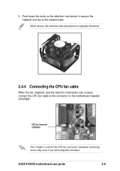
Hardware monitoring errors may occur if you fail to connect the CPU fan connector! Push down the locks on the motherboard labeled CPUFAN1. CPU Fan Connector (CPUFAN1) Don't forget to plug this connector. When secure, the retention locks should point to opposite directions. 2.4.4 Connecting the CPU fan cable When the fan, heatsink, and the retention mechanism are in place, connect the CPU fan cable to the connector on the retention mechanism to secure the heatsink and fan to the module base. ASUS P4S333 motherboard user guide 2-9 3.
Hardware monitoring errors may occur if you fail to connect the CPU fan connector! Push down the locks on the motherboard labeled CPUFAN1. CPU Fan Connector (CPUFAN1) Don't forget to plug this connector. When secure, the retention locks should point to opposite directions. 2.4.4 Connecting the CPU fan cable When the fan, heatsink, and the retention mechanism are in place, connect the CPU fan cable to the connector on the retention mechanism to secure the heatsink and fan to the module base. ASUS P4S333 motherboard user guide 2-9 3.
User Manual
Page 35
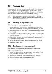
... physically installing the expansion card, configure the card by adjusting the software settings. 1. Turn on the next page. 3. ASUS P4S333 motherboard user guide 2-13 2.6 Expansion slots In the future, you removed earlier. 6. Align the card connector with the slot and press firmly until the card is already installed in a chassis). 3. See Chapter 4 for...
... physically installing the expansion card, configure the card by adjusting the software settings. 1. Turn on the next page. 3. ASUS P4S333 motherboard user guide 2-13 2.6 Expansion slots In the future, you removed earlier. 6. Align the card connector with the slot and press firmly until the card is already installed in a chassis). 3. See Chapter 4 for...
User Manual
Page 44
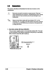
...pin plug. Placing jumper caps over these connector pins will cause damage to the power connector on hard drives and CD-ROM drives, but may be on the opposite side on floppy disk drives. 1. P4S333 ® IDELED1 P4S333 IDE Activity LED 2-22 Chapter 2: ...Hardware information Some pins are clearly distinguished from jumpers in the Motherboard Layout. 2.8 Connectors This section describes and illustrates the internal connectors on the connectors. Pin 1 is usually on the side...
...pin plug. Placing jumper caps over these connector pins will cause damage to the power connector on hard drives and CD-ROM drives, but may be on the opposite side on floppy disk drives. 1. P4S333 ® IDELED1 P4S333 IDE Activity LED 2-22 Chapter 2: ...Hardware information Some pins are clearly distinguished from jumpers in the Motherboard Layout. 2.8 Connectors This section describes and illustrates the internal connectors on the connectors. Pin 1 is usually on the side...
User Manual
Page 45
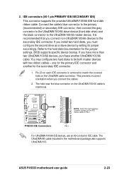
... supports UltraDMA/100. ASUS P4S333 motherboard user guide 2-23 If you install two hard disks, you connect the cables. 2. PIN 1 For UltraDMA/100/66 IDE devices, use an 80-conductor IDE cable. Secondary IDE Connector Primary IDE Connector P4S333 ® P4S333 IDE Connectors NOTE: Orient the... red markings (usually zigzag) on each IDE connector is intentional. Pin 20 on the IDE ribbon cable to the hard disk ...
... supports UltraDMA/100. ASUS P4S333 motherboard user guide 2-23 If you install two hard disks, you connect the cables. 2. PIN 1 For UltraDMA/100/66 IDE devices, use an 80-conductor IDE cable. Secondary IDE Connector Primary IDE Connector P4S333 ® P4S333 IDE Connectors NOTE: Orient the... red markings (usually zigzag) on each IDE connector is intentional. Pin 20 on the IDE ribbon cable to the hard disk ...
User Manual
Page 46
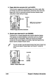
...the motherboard, connect the other end to the floppy drive. (Pin 5 is for a chassis designed with pin 5 plug). P4S333 ® PIN 1 P4S333 Floppy Disk Drive Connector 4. CHASSIS +5VSB_MB Chassis Signal GND P4S333 ® P4S333 Chassis Alarm Lead 2-24 Chapter 2: Hardware information 3. Chassis open alarm lead (4-1 pin CHASSIS) This lead is removed to .... If you remove any chassis component, the sensor triggers and sends a high-level signal to this lead to PIN 1. Floppy disk drive connector (34-1 pin FLOPPY) This connector supports the provided floppy drive ribbon cable.
...the motherboard, connect the other end to the floppy drive. (Pin 5 is for a chassis designed with pin 5 plug). P4S333 ® PIN 1 P4S333 Floppy Disk Drive Connector 4. CHASSIS +5VSB_MB Chassis Signal GND P4S333 ® P4S333 Chassis Alarm Lead 2-24 Chapter 2: Hardware information 3. Chassis open alarm lead (4-1 pin CHASSIS) This lead is removed to .... If you remove any chassis component, the sensor triggers and sends a high-level signal to this lead to PIN 1. Floppy disk drive connector (34-1 pin FLOPPY) This connector supports the provided floppy drive ribbon cable.
User Manual
Page 47
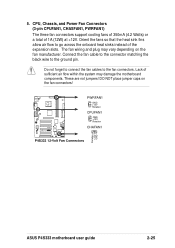
... are not jumpers! PWRFAN1 GND +12V Rotation CPUFAN1 GND +12V Rotation P4S333 ® CHAFAN1 P4S333 12-Volt Fan Connectors Rotation +12V GND ASUS P4S333 motherboard user guide 2-25 CPU, Chassis, and Power Fan Connectors (3-pin CPUFAN1, CHASFAN1, PWRFAN1) The three fan connectors support cooling fans of 350mA (4.2 Watts) or a total of the expansion slots. DO NOT place...
... are not jumpers! PWRFAN1 GND +12V Rotation CPUFAN1 GND +12V Rotation P4S333 ® CHAFAN1 P4S333 12-Volt Fan Connectors Rotation +12V GND ASUS P4S333 motherboard user guide 2-25 CPU, Chassis, and Power Fan Connectors (3-pin CPUFAN1, CHASFAN1, PWRFAN1) The three fan connectors support cooling fans of 350mA (4.2 Watts) or a total of the expansion slots. DO NOT place...
User Manual
Page 48
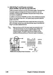
... that you are designed to fit these connectors in only one 4-pin device power plug to the ASUS EZ Plug™ connector labeled AUX12V. ASUS EZ Plug™ and ATX power connectors (20-pin ATXPWR, 4-pin ATX+12V, 4-pin AUX+12V) These connectors connect to the CPU. The plugs from...+3.3VDC ATXPWR Pin 1 +12V GND GND +5V AUX12V +12.0VDC +5VSB PWR_OK COM +5.0VDC COM +5.0VDC COM +3.3VDC +3.3VDC P4S333 ® +12V DC ATX12V P4S333 ATX & Auxiliary Power Connectors +12V DC COM Pin 1 COM 2-26 Chapter 2: Hardware information Make sure that does not have the ATX +12V plug, connect ...
... that you are designed to fit these connectors in only one 4-pin device power plug to the ASUS EZ Plug™ connector labeled AUX12V. ASUS EZ Plug™ and ATX power connectors (20-pin ATXPWR, 4-pin ATX+12V, 4-pin AUX+12V) These connectors connect to the CPU. The plugs from...+3.3VDC ATXPWR Pin 1 +12V GND GND +5V AUX12V +12.0VDC +5VSB PWR_OK COM +5.0VDC COM +5.0VDC COM +3.3VDC +3.3VDC P4S333 ® +12V DC ATX12V P4S333 ATX & Auxiliary Power Connectors +12V DC COM Pin 1 COM 2-26 Chapter 2: Hardware information Make sure that does not have the ATX +12V plug, connect ...
User Manual
Page 49
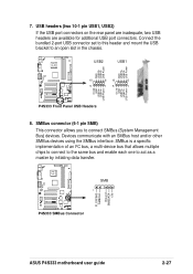
7. USB Power GND USBP5+ USBP5- USB Power P4S333 Front Panel USB Headers 8. FLOATING SMBCLK Ground SMBDATA +3V P4S333 ® SMB 1 P4S333 SMBus Connector ASUS P4S333 motherboard user guide 2-27 USB Power P4S333 ® 10 6 10 6 5 15 1 OC1# GND USBP2+ USBP2- Connect the bundled 2-port USB connector set to this header and mount the USB bracket to connect SMBus (System...
7. USB Power GND USBP5+ USBP5- USB Power P4S333 Front Panel USB Headers 8. FLOATING SMBCLK Ground SMBDATA +3V P4S333 ® SMB 1 P4S333 SMBus Connector ASUS P4S333 motherboard user guide 2-27 USB Power P4S333 ® 10 6 10 6 5 15 1 OC1# GND USBP2+ USBP2- Connect the bundled 2-port USB connector set to this header and mount the USB bracket to connect SMBus (System...
User Manual
Page 50
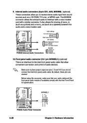
...your audio cable and the front panel audio module (if available) comply with a similar connector. IAPANEL1 LineOut_FL NC LineOut_FR MICPWR MIC LineOut_RL LineOut_RR NC AGND 1 P4S333 ® P4S333 Audio Panel Connector 2-28 Chapter 2: Hardware information By default, these pins are shorted. It also allows ...Intel Front Panel I/O specification. AUX1 (White) Left Audio Channel Ground Ground Right Audio Channel CD1 (Black) P4S333 ® P4S333 Internal Audio Connectors Right Audio Channel Ground Ground Left Audio Channel MODEM Modem-In Ground Ground Modem-Out 10. 9. Internal audio...
...your audio cable and the front panel audio module (if available) comply with a similar connector. IAPANEL1 LineOut_FL NC LineOut_FR MICPWR MIC LineOut_RL LineOut_RR NC AGND 1 P4S333 ® P4S333 Audio Panel Connector 2-28 Chapter 2: Hardware information By default, these pins are shorted. It also allows ...Intel Front Panel I/O specification. AUX1 (White) Left Audio Channel Ground Ground Right Audio Channel CD1 (Black) P4S333 ® P4S333 Internal Audio Connectors Right Audio Channel Ground Ground Left Audio Channel MODEM Modem-In Ground Ground Modem-Out 10. 9. Internal audio...


