User Manual
Page 4
Safeguards Contents 2.6.4 AGP slot 2-15 2.6.5 ACR slot 2-16 2.7 Switches and jumpers 2-17 2.8 Connectors 2-22 Chapter 3: Powering up 3-1 3.1 Starting up for the first time 3-1 3.2 Vocal POST Messages 3-2 3.3 Powering off the computer 3-4 Chapter 4: BIOS setup 4-1 4.1 Managing and updating your BIOS 4-1 4.1.1 ...
Safeguards Contents 2.6.4 AGP slot 2-15 2.6.5 ACR slot 2-16 2.7 Switches and jumpers 2-17 2.8 Connectors 2-22 Chapter 3: Powering up 3-1 3.1 Starting up for the first time 3-1 3.2 Vocal POST Messages 3-2 3.3 Powering off the computer 3-4 Chapter 4: BIOS setup 4-1 4.1 Managing and updating your BIOS 4-1 4.1.1 ...
User Manual
Page 7
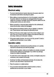
... try to the correct voltage in any damage, contact your dealer immediately. • To avoid short circuits, keep paper clips, screws, and staples away from connectors, slots, sockets and circuitry. • Avoid dust, humidity, and temperature extremes. Contact a qualified service technician or your retailer. If you are using, contact your local...
... try to the correct voltage in any damage, contact your dealer immediately. • To avoid short circuits, keep paper clips, screws, and staples away from connectors, slots, sockets and circuitry. • Avoid dust, humidity, and temperature extremes. Contact a qualified service technician or your retailer. If you are using, contact your local...
User Manual
Page 8
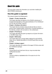
... • Index This part contains an alphabetical list of the topics found in this document. It includes description of the switches, jumpers, and connectors on the motherboard. • Chapter 3: Powering up This chapter describes the power up sequence and gives information on the BIOS beep codes. ...support CD that comes with the motherboard package. • Glossary This part lists the technical terms that you need when installing the ASUS P4S333 motherboard. How this guide This user guide contains the information you have to change system settings through the BIOS Setup menus. About...
... • Index This part contains an alphabetical list of the topics found in this document. It includes description of the switches, jumpers, and connectors on the motherboard. • Chapter 3: Powering up This chapter describes the power up sequence and gives information on the BIOS beep codes. ...support CD that comes with the motherboard package. • Glossary This part lists the technical terms that you need when installing the ASUS P4S333 motherboard. How this guide This user guide contains the information you have to change system settings through the BIOS Setup menus. About...
User Manual
Page 14
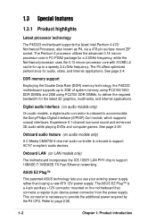
... known as P4, via a 478-pin surface mount ZIF socket. DDR memory support Employing the Double Data Rate (DDR) memory technology, the P4S333 motherboard supports up to accommodate the Sony/Philips Digital Interface (S/PDIF) Out module, which supports coaxial interfaces. Onboard audio feature (on audio models... AC'97 compliant audio devices. Onboard LAN (on the motherboard that connects a regular 4-pin device power connector from the power supply. ASUS EZ Plug™ This patented ASUS technology lets you use your existing power supply rather than buying a new ATX 12V power supply. Refer ...
... known as P4, via a 478-pin surface mount ZIF socket. DDR memory support Employing the Double Data Rate (DDR) memory technology, the P4S333 motherboard supports up to accommodate the Sony/Philips Digital Interface (S/PDIF) Out module, which supports coaxial interfaces. Onboard audio feature (on audio models... AC'97 compliant audio devices. Onboard LAN (on the motherboard that connects a regular 4-pin device power connector from the power supply. ASUS EZ Plug™ This patented ASUS technology lets you use your existing power supply rather than buying a new ATX 12V power supply. Refer ...
User Manual
Page 15
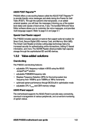
...The P4S333 includes special connectors that support optional readers for authenticating online transactions, editing IC-based information, and more. The Smart Card Reader promotes cutting-edge technology featuring increased security for Smart Card, Secure Digital (SD) memory Card, and Memory Stick (MS). ASUS P4S333 ...Winbond Voice Editor software allows you of the system boot status and causes of system status. ASUS POST Reporter™ P4S333 offers a new exciting feature called the ASUS POST Reporter™ to provide easy connectivity, one-touch management of various peripherals, and ...
...The P4S333 includes special connectors that support optional readers for authenticating online transactions, editing IC-based information, and more. The Smart Card Reader promotes cutting-edge technology featuring increased security for Smart Card, Secure Digital (SD) memory Card, and Memory Stick (MS). ASUS P4S333 ...Winbond Voice Editor software allows you of the system boot status and causes of system status. ASUS POST Reporter™ P4S333 offers a new exciting feature called the ASUS POST Reporter™ to provide easy connectivity, one-touch management of various peripherals, and ...
User Manual
Page 16
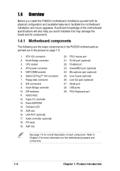
...slot 16. LAN PHY (optional) 17. RJ-45 port (optional) 22. IDE connectors 9. AGP slot 20. CPU socket 4. DDR DIMM sockets 6. Onboard LED 15. PS/2 mouse port 21. ATX 12V connector 2. ASUS ASIC 12. Line Out jack (optional) 27. DIP switches 11. Audio controller (...board and its physical configuration and available features to Chapter 2 for a brief description of the P4S333 motherboard as pointed out in the picture on the motherboard jumpers and connectors. 1-4 Chapter 1: Product introduction USB ports 29. A sufficient knowledge of the motherboard specifications ...
...slot 16. LAN PHY (optional) 17. RJ-45 port (optional) 22. IDE connectors 9. AGP slot 20. CPU socket 4. DDR DIMM sockets 6. Onboard LED 15. PS/2 mouse port 21. ATX 12V connector 2. ASUS ASIC 12. Line Out jack (optional) 27. DIP switches 11. Audio controller (...board and its physical configuration and available features to Chapter 2 for a brief description of the P4S333 motherboard as pointed out in the picture on the motherboard jumpers and connectors. 1-4 Chapter 1: Product introduction USB ports 29. A sufficient knowledge of the motherboard specifications ...
User Manual
Page 18
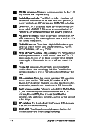
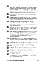
...disk cable. 8 IDE connectors. This socket accommodates the Intel® Pentium® 4 478/Northwood Processor with AC'97 Interface, Ethernet MAC, Dual Universal Serial Bus Host controllers, IDE Master/Slave controllers, and the MuTIOL Connect to set the CPU external frequency. 11 ASUS ASIC. These three 184...-pin DIMM sockets support up to 3GB system memory using unbuffered non-ECC PC2100/ 1600 DDR DIMMs, 2GB using PC2700. 6 ASUS EZ Plug™ Auxiliary +12V connector. This 5-switch Dual Inline Package (DIP) allows you don't have at least 1A on the +5V standby lead (+5VSB). 5...
...disk cable. 8 IDE connectors. This socket accommodates the Intel® Pentium® 4 478/Northwood Processor with AC'97 Interface, Ethernet MAC, Dual Universal Serial Bus Host controllers, IDE Master/Slave controllers, and the MuTIOL Connect to set the CPU external frequency. 11 ASUS ASIC. These three 184...-pin DIMM sockets support up to 3GB system memory using unbuffered non-ECC PC2100/ 1600 DDR DIMMs, 2GB using PC2700. 6 ASUS EZ Plug™ Auxiliary +12V connector. This 5-switch Dual Inline Package (DIP) allows you don't have at least 1A on the +5V standby lead (+5VSB). 5...
User Manual
Page 19
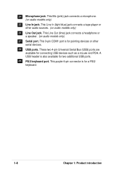
... a Local Area Network (LAN) through a network hub. (on audio models only) ASUS P4S333 motherboard user guide 1-7 This 25-pin port connects a parallel printer, a scanner, or other devices. 23 Game/MIDI port. This green 6-pin connector is a standby power on the motherboard. This connector supports a joystick or a game pad for playing games, and MIDI devices...
... a Local Area Network (LAN) through a network hub. (on audio models only) ASUS P4S333 motherboard user guide 1-7 This 25-pin port connects a parallel printer, a scanner, or other devices. 23 Game/MIDI port. This green 6-pin connector is a standby power on the motherboard. This connector supports a joystick or a game pad for playing games, and MIDI devices...
User Manual
Page 20
... devices such as a mouse and PDA. This Line In (light blue) jack connects a tape player or other serial devices. 28 USB ports. This purple 6-pin connector is for two additional USB ports. 29 PS/2 keyboard port. 24 Microphone jack. These two 4-pin Universal Serial Bus (USB) ports are available for a PS...
... devices such as a mouse and PDA. This Line In (light blue) jack connects a tape player or other serial devices. 28 USB ports. This purple 6-pin connector is for two additional USB ports. 29 PS/2 keyboard port. 24 Microphone jack. These two 4-pin Universal Serial Bus (USB) ports are available for a PS...
User Manual
Page 21
It includes details on the switches, jumpers, and connectors on the motherboard. Hardware information Chapter 2 This chapter describes the hardware setup procedures that you have to perform when installing system components.
It includes details on the switches, jumpers, and connectors on the motherboard. Hardware information Chapter 2 This chapter describes the hardware setup procedures that you have to perform when installing system components.

User Manual
Page 24
....0in) 2.2 Motherboard layout PS/2KBMS T: Mouse B: Keyboard USB Top: T: USB1 RJ-45 B: USB2 COM1 VEN1 KBPWR1 USBV1 22cm (8.7in) ATX Power Connector PWRFAN1 AUX12V1 DDRVOL1 DDR DIMM1 (64/72 bit, 184-pin module) DDR DIMM2 (64/72 bit, 184-pin module) DDR DIMM3 (64/72 bit, 184... AGP 01 23 45 PCI1 PCI2 SiS961 MuTLOL Media I/O JEN1 PWRTMP1 SIRQ1 PCI3 P4S333 PCI4 LED1 ® PCI5 PCI6 USB2 ACR1 CLRCMOS1 SMART CR2032 3V Lithium Cell CMOS Power Super I/O SMB1 SMARTCON1 IR1 CHASSIS1 ASUS ASIC with Hardware Monitor 2Mbit Firmware Hub CHASFAN1 USBV2 USBV3 USB1 IPANEL1 IDELED1 PANEL1...
....0in) 2.2 Motherboard layout PS/2KBMS T: Mouse B: Keyboard USB Top: T: USB1 RJ-45 B: USB2 COM1 VEN1 KBPWR1 USBV1 22cm (8.7in) ATX Power Connector PWRFAN1 AUX12V1 DDRVOL1 DDR DIMM1 (64/72 bit, 184-pin module) DDR DIMM2 (64/72 bit, 184-pin module) DDR DIMM3 (64/72 bit, 184... AGP 01 23 45 PCI1 PCI2 SiS961 MuTLOL Media I/O JEN1 PWRTMP1 SIRQ1 PCI3 P4S333 PCI4 LED1 ® PCI5 PCI6 USB2 ACR1 CLRCMOS1 SMART CR2032 3V Lithium Cell CMOS Power Super I/O SMB1 SMARTCON1 IR1 CHASSIS1 ASUS ASIC with Hardware Monitor 2Mbit Firmware Hub CHASFAN1 USBV2 USBV3 USB1 IPANEL1 IDELED1 PANEL1...
User Manual
Page 31
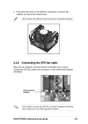
Push down the locks on the motherboard labeled CPUFAN1. CPU Fan Connector (CPUFAN1) Don't forget to plug this connector. Hardware monitoring errors may occur if you fail to connect the CPU fan connector! When secure, the retention locks should point to opposite directions. 2.4.4 Connecting the CPU fan cable When the fan, heatsink, and the retention mechanism are in place, connect the CPU fan cable to the connector on the retention mechanism to secure the heatsink and fan to the module base. ASUS P4S333 motherboard user guide 2-9 3.
Push down the locks on the motherboard labeled CPUFAN1. CPU Fan Connector (CPUFAN1) Don't forget to plug this connector. Hardware monitoring errors may occur if you fail to connect the CPU fan connector! When secure, the retention locks should point to opposite directions. 2.4.4 Connecting the CPU fan cable When the fan, heatsink, and the retention mechanism are in place, connect the CPU fan cable to the connector on the retention mechanism to secure the heatsink and fan to the module base. ASUS P4S333 motherboard user guide 2-9 3.
User Manual
Page 35
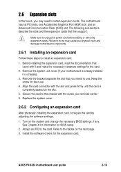
... by adjusting the software settings. 1. Assign an IRQ to unplug the power cord before adding or removing expansion cards. ASUS P4S333 motherboard user guide 2-13 Make sure to the card. Align the card connector with it and make the necessary hardware settings for the expansion card. Install the software drivers for the card...
... by adjusting the software settings. 1. Assign an IRQ to unplug the power cord before adding or removing expansion cards. ASUS P4S333 motherboard user guide 2-13 Make sure to the card. Align the card connector with it and make the necessary hardware settings for the expansion card. Install the software drivers for the card...
User Manual
Page 44
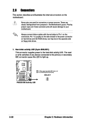
... Motherboard Layout. Pin 1 is usually on the side closest to your motherboard. P4S333 ® IDELED1 P4S333 IDE Activity LED 2-22 Chapter 2: Hardware information 2.8 Connectors This section describes and illustrates the internal connectors on the motherboard. Hard disk activity LED (2-pin IDELED1) This connector supplies power to light up. The read or write activities of any...
... Motherboard Layout. Pin 1 is usually on the side closest to your motherboard. P4S333 ® IDELED1 P4S333 IDE Activity LED 2-22 Chapter 2: Hardware information 2.8 Connectors This section describes and illustrates the internal connectors on the motherboard. Hard disk activity LED (2-pin IDELED1) This connector supplies power to light up. The read or write activities of any...
User Manual
Page 45
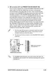
...hole near the blue connector on each IDE connector is removed to the hard disk documentation for the jumper settings. ASUS P4S333 motherboard user guide 2-23 Connect the cable's blue connector to the primary (recommended) or secondary IDE connector, then connect the gray connector to the UltraDMA/100.../66 slave device (hard disk drive) and the black connector to be both master...
...hole near the blue connector on each IDE connector is removed to the hard disk documentation for the jumper settings. ASUS P4S333 motherboard user guide 2-23 Connect the cable's blue connector to the primary (recommended) or secondary IDE connector, then connect the gray connector to the UltraDMA/100.../66 slave device (hard disk drive) and the black connector to be both master...
User Manual
Page 46
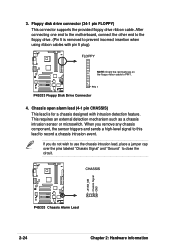
... and sends a high-level signal to this lead to record a chassis intrusion event. 3. Floppy disk drive connector (34-1 pin FLOPPY) This connector supports the provided floppy drive ribbon cable. FLOPPY NOTE: Orient the red markings on the floppy ribbon cable to... insertion when using ribbon cables with intrusion detection feature. CHASSIS +5VSB_MB Chassis Signal GND P4S333 ® P4S333 Chassis Alarm Lead 2-24 Chapter 2: Hardware information P4S333 ® PIN 1 P4S333 Floppy Disk Drive Connector 4. After connecting one end to the motherboard, connect the other end to PIN 1....
... and sends a high-level signal to this lead to record a chassis intrusion event. 3. Floppy disk drive connector (34-1 pin FLOPPY) This connector supports the provided floppy drive ribbon cable. FLOPPY NOTE: Orient the red markings on the floppy ribbon cable to... insertion when using ribbon cables with intrusion detection feature. CHASSIS +5VSB_MB Chassis Signal GND P4S333 ® P4S333 Chassis Alarm Lead 2-24 Chapter 2: Hardware information P4S333 ® PIN 1 P4S333 Floppy Disk Drive Connector 4. After connecting one end to the motherboard, connect the other end to PIN 1....
User Manual
Page 47
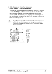
5. Connect the fan cable to the connector matching the black wire to the fan connectors. Lack of the expansion slots. DO NOT place jumper caps on the fan manufacturer. Do not forget to connect the fan cables...within the system may vary depending on the fan connectors! PWRFAN1 GND +12V Rotation CPUFAN1 GND +12V Rotation P4S333 ® CHAFAN1 P4S333 12-Volt Fan Connectors Rotation +12V GND ASUS P4S333 motherboard user guide 2-25 CPU, Chassis, and Power Fan Connectors (3-pin CPUFAN1, CHASFAN1, PWRFAN1) The three fan connectors support cooling fans of 350mA (4.2 Watts) or...
5. Connect the fan cable to the connector matching the black wire to the fan connectors. Lack of the expansion slots. DO NOT place jumper caps on the fan manufacturer. Do not forget to connect the fan cables...within the system may vary depending on the fan connectors! PWRFAN1 GND +12V Rotation CPUFAN1 GND +12V Rotation P4S333 ® CHAFAN1 P4S333 12-Volt Fan Connectors Rotation +12V GND ASUS P4S333 motherboard user guide 2-25 CPU, Chassis, and Power Fan Connectors (3-pin CPUFAN1, CHASFAN1, PWRFAN1) The three fan connectors support cooling fans of 350mA (4.2 Watts) or...
User Manual
Page 48
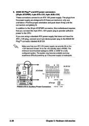
... +5VSB PWR_OK COM +5.0VDC COM +5.0VDC COM +3.3VDC +3.3VDC P4S333 ® +12V DC ATX12V P4S333 ATX & Auxiliary Power Connectors +12V DC COM Pin 1 COM 2-26 Chapter 2: Hardware information ASUS EZ Plug™ and ATX power connectors (20-pin ATXPWR, 4-pin ATX+12V, 4-pin AUX+12V) These connectors connect to the CPU. Find the proper orientation and...
... +5VSB PWR_OK COM +5.0VDC COM +5.0VDC COM +3.3VDC +3.3VDC P4S333 ® +12V DC ATX12V P4S333 ATX & Auxiliary Power Connectors +12V DC COM Pin 1 COM 2-26 Chapter 2: Hardware information ASUS EZ Plug™ and ATX power connectors (20-pin ATXPWR, 4-pin ATX+12V, 4-pin AUX+12V) These connectors connect to the CPU. Find the proper orientation and...
User Manual
Page 49
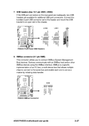
... by initiating data transfer. USB2 USB1 GND USBP3+ USBP3- FLOATING SMBCLK Ground SMBDATA +3V P4S333 ® SMB 1 P4S333 SMBus Connector ASUS P4S333 motherboard user guide 2-27 USB Power P4S333 ® 10 6 10 6 5 15 1 OC1# GND USBP2+ USBP2- Connect the bundled 2-port USB connector set to this header and mount the USB bracket to an open slot in...
... by initiating data transfer. USB2 USB1 GND USBP3+ USBP3- FLOATING SMBCLK Ground SMBDATA +3V P4S333 ® SMB 1 P4S333 SMBus Connector ASUS P4S333 motherboard user guide 2-27 USB Power P4S333 ® 10 6 10 6 5 15 1 OC1# GND USBP2+ USBP2- Connect the bundled 2-port USB connector set to this header and mount the USB bracket to an open slot in...
User Manual
Page 50
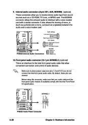
... front panel audio cable. IAPANEL1 LineOut_FL NC LineOut_FR MICPWR MIC LineOut_RL LineOut_RR NC AGND 1 P4S333 ® P4S333 Audio Panel Connector 2-28 Chapter 2: Hardware information AUX1 (White) Left Audio Channel Ground Ground Right Audio Channel CD1 (Black) P4S333 ® P4S333 Internal Audio Connectors Right Audio Channel Ground Ground Left Audio Channel MODEM Modem-In Ground Ground Modem...
... front panel audio cable. IAPANEL1 LineOut_FL NC LineOut_FR MICPWR MIC LineOut_RL LineOut_RR NC AGND 1 P4S333 ® P4S333 Audio Panel Connector 2-28 Chapter 2: Hardware information AUX1 (White) Left Audio Channel Ground Ground Right Audio Channel CD1 (Black) P4S333 ® P4S333 Internal Audio Connectors Right Audio Channel Ground Ground Left Audio Channel MODEM Modem-In Ground Ground Modem...


