
P4PE-X User Manual
Page 6
...using , contact your local power company. • If the power supply is set to or from the system, ensure that the power cables for the devices are unplugged before you add a device. • Before connecting or removing signal cables from the motherboard, ensure that all the manuals.... Operation safety • Before installing the motherboard and adding devices on a stable surface. • If you encounter technical problems with the package. • Before using the product, make sure all cables are correctly connected and the power cables are not damaged. Contact a qualified ...
...using , contact your local power company. • If the power supply is set to or from the system, ensure that the power cables for the devices are unplugged before you add a device. • Before connecting or removing signal cables from the motherboard, ensure that all the manuals.... Operation safety • Before installing the motherboard and adding devices on a stable surface. • If you encounter technical problems with the package. • Before using the product, make sure all cables are correctly connected and the power cables are not damaged. Contact a qualified ...
P4PE-X User Manual
Page 15
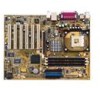
...power on the +5V standby lead (+5VSB). 6 Floppy disk connector. The fourth-generation Intel I /O APIC, SMBus 2.0 controller, LPC interface, AC'97 2.2 interface, and PCI 2.2 interface. This LED acts as a reminder to the south bridge ICH4 via the Intel® proprietary Hub Interface. 4 DDR DIMM sockets. ASUS P4PE-X motherboard...maximum throughput. The MCH interconnects to turn off the system power before plugging or unplugging devices. 11 ASUS ASIC. This 2Mb firmware contains the programmable BIOS program. 10 Standby power LED. These dual-channel bus master IDE connectors support ...
...power on the +5V standby lead (+5VSB). 6 Floppy disk connector. The fourth-generation Intel I /O APIC, SMBus 2.0 controller, LPC interface, AC'97 2.2 interface, and PCI 2.2 interface. This LED acts as a reminder to the south bridge ICH4 via the Intel® proprietary Hub Interface. 4 DDR DIMM sockets. ASUS P4PE-X motherboard...maximum throughput. The MCH interconnects to turn off the system power before plugging or unplugging devices. 11 ASUS ASIC. This 2Mb firmware contains the programmable BIOS program. 10 Standby power LED. These dual-channel bus master IDE connectors support ...

P4PE-X User Manual
Page 17
SEC_IDE PRI_IDE ATX Power Connector FLOPPY1 1.5 Motherboard layout PS/2KBMS T: Mouse B: Keyboard USB2.0 T: USB4 B: USB3 COM1 KBPWR1 22.86cm (9.0in) Socket 478 CPU_FAN1 CHA_FAN1 DDR DIMM1 (64/72 bit, 184-pin module) ... 845PE Memory Controller Hub (MCH) Accelerated Graphics Port (AGP) PCI1 P4PE-X PCI2 PCI3 PCI4 PCI5 PCI6 01 23 45 Intel I/O Controller Hub (ICH4) ® CR2032 3V Lithium Cell CMOS Power CLRTC ASUS ASIC with Hardware Monitor SB_PWR1 CHASSIS1 4Mbit Firmware Hub Super I/O IDE_LED1 FP_AUDIO1 USB_56 GAME1 PANEL1 30.5cm (12.0in) ASUS P4PE-X motherboard user guide 1-7
SEC_IDE PRI_IDE ATX Power Connector FLOPPY1 1.5 Motherboard layout PS/2KBMS T: Mouse B: Keyboard USB2.0 T: USB4 B: USB3 COM1 KBPWR1 22.86cm (9.0in) Socket 478 CPU_FAN1 CHA_FAN1 DDR DIMM1 (64/72 bit, 184-pin module) ... 845PE Memory Controller Hub (MCH) Accelerated Graphics Port (AGP) PCI1 P4PE-X PCI2 PCI3 PCI4 PCI5 PCI6 01 23 45 Intel I/O Controller Hub (ICH4) ® CR2032 3V Lithium Cell CMOS Power CLRTC ASUS ASIC with Hardware Monitor SB_PWR1 CHASSIS1 4Mbit Firmware Hub Super I/O IDE_LED1 FP_AUDIO1 USB_56 GAME1 PANEL1 30.5cm (12.0in) ASUS P4PE-X motherboard user guide 1-7

P4PE-X User Manual
Page 18
... you uninstall any component, place it on them due to avoid touching the ICs on a grounded antistatic pad or in any motherboard component. ® P4PE-X P4PE-X Onboard LED SB_PWR1 ON Standby Power OFF Powered Off 1-8 Chapter 1: Product introduction When lit, the standby LED (SB_PWR1) indicates that the system is detached from the wall socket before...
... you uninstall any component, place it on them due to avoid touching the ICs on a grounded antistatic pad or in any motherboard component. ® P4PE-X P4PE-X Onboard LED SB_PWR1 ON Standby Power OFF Powered Off 1-8 Chapter 1: Product introduction When lit, the standby LED (SB_PWR1) indicates that the system is detached from the wall socket before...

P4PE-X User Manual
Page 19
...power cord before installing or removing the motherboard. Make sure to the chassis. Doing so may cause you physical injury and damage motherboard components. 1.7.1 Placement direction When installing the motherboard, make sure that measures 12 inches x 9 inches (30.5 cm x 22.9 cm). Place this side towards the rear of the chassis ASUS P4PE-X motherboard... user guide 1-9 The edge with external ports goes to the rear part of the chassis as indicated in the correct orientation. Do not overtighten the screws! The motherboard uses the ATX ...
...power cord before installing or removing the motherboard. Make sure to the chassis. Doing so may cause you physical injury and damage motherboard components. 1.7.1 Placement direction When installing the motherboard, make sure that measures 12 inches x 9 inches (30.5 cm x 22.9 cm). Place this side towards the rear of the chassis ASUS P4PE-X motherboard... user guide 1-9 The edge with external ports goes to the rear part of the chassis as indicated in the correct orientation. Do not overtighten the screws! The motherboard uses the ATX ...
P4PE-X User Manual
Page 20
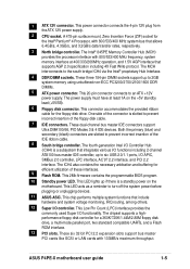
1.8 Central Processing Unit (CPU) 1.8.1 Overview The motherboard comes with 512KB L2 cache on 0.13 micron process. If you installed a CPU with 800MHz FSB, you installed a CPU that the item Hyper-Threading Technology ... of the CPU socket. Under Linux, use the Hyper-Threading compliler to Enabled. Install a Pentium 4 CPU that the CPU has a gold triangular mark on this motherboard: 1. Note in BIOS before installing a supported operating system. 4. It is supported under Windows XP and Linux 2.4.x (kernel) and later versions only. Gold Mark Incorrect installation...
1.8 Central Processing Unit (CPU) 1.8.1 Overview The motherboard comes with 512KB L2 cache on 0.13 micron process. If you installed a CPU with 800MHz FSB, you installed a CPU that the item Hyper-Threading Technology ... of the CPU socket. Under Linux, use the Hyper-Threading compliler to Enabled. Install a Pentium 4 CPU that the CPU has a gold triangular mark on this motherboard: 1. Note in BIOS before installing a supported operating system. 4. It is supported under Windows XP and Linux 2.4.x (kernel) and later versions only. Gold Mark Incorrect installation...

P4PE-X User Manual
Page 23
... snap back in place and the DIMM is properly seated. Unlocked Retaining Clip ASUS P4PE-X motherboard user guide 1-13 Follow these steps to ensure system stability. DDR DIMM notch 2. Failure to do so may cause severe damage to unplug the power supply before adding or removing DIMMs or other system components. Unlock a DIMM socket...
... snap back in place and the DIMM is properly seated. Unlocked Retaining Clip ASUS P4PE-X motherboard user guide 1-13 Follow these steps to ensure system stability. DDR DIMM notch 2. Failure to do so may cause severe damage to unplug the power supply before adding or removing DIMMs or other system components. Unlock a DIMM socket...

P4PE-X User Manual
Page 25
... of date, time, and system setup information by erasing the CMOS RTC RAM data. KBPWR1 12 23 P4PE-X +5V +5VSB ® (Default) P4PE-X Keyboard Power Setting 2. Plug the power cord and turn ON the computer. 4. For system failure due to overclocking. Clear RTC RAM (CLRTC1)... the system hangs due to overclocking, use the C.P.R. (CPU Parameter Recall) feature. Keyboard power (3-pin KBPWR1) This jumper allows you press a key on the +5VSB lead, and a corresponding setting in CMOS. ASUS P4PE-X motherboard user guide 1-15 Move the jumper cap from pins 1-2 (default) to pins 1-2. ...
... of date, time, and system setup information by erasing the CMOS RTC RAM data. KBPWR1 12 23 P4PE-X +5V +5VSB ® (Default) P4PE-X Keyboard Power Setting 2. Plug the power cord and turn ON the computer. 4. For system failure due to overclocking. Clear RTC RAM (CLRTC1)... the system hangs due to overclocking, use the C.P.R. (CPU Parameter Recall) feature. Keyboard power (3-pin KBPWR1) This jumper allows you press a key on the +5VSB lead, and a corresponding setting in CMOS. ASUS P4PE-X motherboard user guide 1-15 Move the jumper cap from pins 1-2 (default) to pins 1-2. ...

P4PE-X User Manual
Page 26
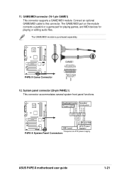
...detection mechanism such as a chassis intrusion sensor or microswitch. CHASSIS1 +5VSB_MB Chassis Signal GND ® P4PE-X P4PE-X Chassis Alarm Lead (Default) 1-16 Chapter 1: Product introduction P4PE-X IDE_LED1 P4PE-X HD Activity LED 2. By default, the pins labeled "Chassis Signal" and "Ground" are ...Hard disk activity LED (2-pin IDE_LED1) This connector supplies power to light up , try reversing the 2-pin plug. 1.12 Connectors This section describes and illustrates the internal connectors on the motherboard. 1. The read or write activities of any chassis component...
...detection mechanism such as a chassis intrusion sensor or microswitch. CHASSIS1 +5VSB_MB Chassis Signal GND ® P4PE-X P4PE-X Chassis Alarm Lead (Default) 1-16 Chapter 1: Product introduction P4PE-X IDE_LED1 P4PE-X HD Activity LED 2. By default, the pins labeled "Chassis Signal" and "Ground" are ...Hard disk activity LED (2-pin IDE_LED1) This connector supplies power to light up , try reversing the 2-pin plug. 1.12 Connectors This section describes and illustrates the internal connectors on the motherboard. 1. The read or write activities of any chassis component...

P4PE-X User Manual
Page 28
... may experience difficulty powering up if the power supply is purchased separately. ® P4PE-X +5V SPDIFOUT GND SPDIF1 P4PE-X Digital Audio Connector 1-18 Chapter 1: Product introduction Find the proper orientation and push down firmly until the connectors completely fit. Connect one orientation. ATX power connectors (20-pin...fully configured system. In addition to the 20-pin ATXPWR connector, this motherboard requires that your ATX 12V power supply can provide 8A on the +12V lead and at least 1A on the motherboard, and the other end to the S/PDIF Out connector on the +5-...
... may experience difficulty powering up if the power supply is purchased separately. ® P4PE-X +5V SPDIFOUT GND SPDIF1 P4PE-X Digital Audio Connector 1-18 Chapter 1: Product introduction Find the proper orientation and push down firmly until the connectors completely fit. Connect one orientation. ATX power connectors (20-pin...fully configured system. In addition to the 20-pin ATXPWR connector, this motherboard requires that your ATX 12V power supply can provide 8A on the +12V lead and at least 1A on the motherboard, and the other end to the S/PDIF Out connector on the +5-...

P4PE-X User Manual
Page 29
...CPU, Chassis, and Power Fan Connectors (3-pin CPU_FAN1, CHA_FAN1) The fan connectors support cooling fans of 350mA~740mA (8.88W max.) or a total of sufficient air flow within the system may damage the motherboard components. DO NOT place jumper caps on the motherboard, making sure that the...from sound sources such as a CD-ROM, TV tuner, or MPEG card. ® P4PE-X CD1(Black) AUX1 (White) Left Audio Channel Ground Ground Right Audio Channel P4PE-X Internal Audio Connectors ASUS P4PE-X motherboard user guide 1-19 Internal audio connectors (4-pin CD1, AUX1) These connectors allow you to ...
...CPU, Chassis, and Power Fan Connectors (3-pin CPU_FAN1, CHA_FAN1) The fan connectors support cooling fans of 350mA~740mA (8.88W max.) or a total of sufficient air flow within the system may damage the motherboard components. DO NOT place jumper caps on the motherboard, making sure that the...from sound sources such as a CD-ROM, TV tuner, or MPEG card. ® P4PE-X CD1(Black) AUX1 (White) Left Audio Channel Ground Ground Right Audio Channel P4PE-X Internal Audio Connectors ASUS P4PE-X motherboard user guide 1-19 Internal audio connectors (4-pin CD1, AUX1) These connectors allow you to ...
P4PE-X User Manual
Page 31
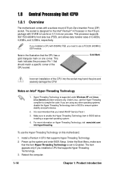
...playing games, and MIDI devices for playing or editing audio files. The GAME/MIDI module is purchased separately. ® P4PE-X P4PE-X Game Connector +5V J1B2 J1CY GND GND J1CX J1B1 +5V GAME1 1 MIDI_IN J2B2 J2CY MIDI_OUT J2CX J2B1 +5V 12. Keyboard ... Ground Ground Speaker ExtSMI# Ground PWRBIN Ground Reset Ground ® P4PE-X Reset SW SMI Lead ATX Power Switch* * Requires an ATX power supply. Connect an optional GAME/MIDI cable to this connector. P4PE-X System Panel Connectors ASUS P4PE-X motherboard user guide 1-21 System panel connector (20-pin PANEL1) This ...
...playing games, and MIDI devices for playing or editing audio files. The GAME/MIDI module is purchased separately. ® P4PE-X P4PE-X Game Connector +5V J1B2 J1CY GND GND J1CX J1B1 +5V GAME1 1 MIDI_IN J2B2 J2CY MIDI_OUT J2CX J2B1 +5V 12. Keyboard ... Ground Ground Speaker ExtSMI# Ground PWRBIN Ground Reset Ground ® P4PE-X Reset SW SMI Lead ATX Power Switch* * Requires an ATX power supply. Connect an optional GAME/MIDI cable to this connector. P4PE-X System Panel Connectors ASUS P4PE-X motherboard user guide 1-21 System panel connector (20-pin PANEL1) This ...

P4PE-X User Manual
Page 34
... the Power-On Self Tests (POST). You will copy file from A:\, Press [ESC] to update the BIOS The ASUS EZ Flash feature allows you see ASUS contact information on a piece of booting from the ASUS website ... (C) 2002, ASUSTeK COMPUTER INC. [Onboard BIOS Information] BIOS Version : ASUS P4PE-X ACPI BIOS Revision 1002 BIOS Model : P4PE-X BIOS Built Date : 04/16/02 Please Enter File Name for NEW...DOS-based utility. Reboot the computer. 3. Insert the disk that you save a copy of the motherboard's original BIOS to a bootable floppy disk in the BIOS firmware so it is built-in case ...
... the Power-On Self Tests (POST). You will copy file from A:\, Press [ESC] to update the BIOS The ASUS EZ Flash feature allows you see ASUS contact information on a piece of booting from the ASUS website ... (C) 2002, ASUSTeK COMPUTER INC. [Onboard BIOS Information] BIOS Version : ASUS P4PE-X ACPI BIOS Revision 1002 BIOS Model : P4PE-X BIOS Built Date : 04/16/02 Please Enter File Name for NEW...DOS-based utility. Reboot the computer. 3. Insert the disk that you save a copy of the motherboard's original BIOS to a bootable floppy disk in the BIOS firmware so it is built-in case ...

P4PE-X User Manual
Page 39
...three short beeps High frequency beeps when system is working Meaning No error during POST indicating the failure. System running at a lower frequency ASUS P4PE-X motherboard user guide 2-7 The bootable floppy disk could be the one that the computer boots from a floppy disk and update the BIOS in...utility. 3. Follow the BIOS update procedure in section "2.1.2 Using AFLASH to update the BIOS." 2.1.4 BIOS beep codes When you turn the power on the computer, and when prompted, place the bootable floppy disk into the floppy drive, so that you created following table for the ...
...three short beeps High frequency beeps when system is working Meaning No error during POST indicating the failure. System running at a lower frequency ASUS P4PE-X motherboard user guide 2-7 The bootable floppy disk could be the one that the computer boots from a floppy disk and update the BIOS in...utility. 3. Follow the BIOS update procedure in section "2.1.2 Using AFLASH to update the BIOS." 2.1.4 BIOS beep codes When you turn the power on the computer, and when prompted, place the bootable floppy disk into the floppy drive, so that you created following table for the ...
P4PE-X User Manual
Page 40
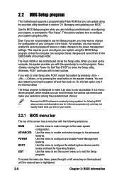
Even if you are not prompted to use as possible. This requires you to configure and enable Power Management features. 2.2 BIOS Setup program This motherboard supports a programmable Flash ROM that the computer can recognize these changes and record them in the CMOS RAM of...may want to change the configuration of the screen has a menu bar with the following BIOS setup screens and descriptions are installing a motherboard, reconfiguring your selections among the predetermined choices. The Setup program is a menudriven program, which means you can also restart by pressing...
Even if you are not prompted to use as possible. This requires you to configure and enable Power Management features. 2.2 BIOS Setup program This motherboard supports a programmable Flash ROM that the computer can recognize these changes and record them in the CMOS RAM of...may want to change the configuration of the screen has a menu bar with the following BIOS setup screens and descriptions are installing a motherboard, reconfiguring your selections among the predetermined choices. The Setup program is a menudriven program, which means you can also restart by pressing...
P4PE-X User Manual
Page 43
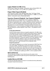
...: [None] [360K, 5.25 in.] [1.2M , 5.25 in.] [720K , 3.5 in.] [1.44M, 3.5 in.] [2.88M, 3.5 in.] Floppy 3 Mode Support [Disabled] This is powered by erasing the CMOS Real Time Clock (RTC) RAM. The Floppy 3 Mode feature allows reading and writing of errors that will cause the system to... installed. Symbols and other characters are not case sensitive, meaning, passwords typed in a password then press . If you to update the BIOS. ASUS P4PE-X motherboard user guide 2-11 Legacy Diskette A [1.44M, 3.5 in the Main menu. You can type up the system. To confirm the password, type...
...: [None] [360K, 5.25 in.] [1.2M , 5.25 in.] [720K , 3.5 in.] [1.44M, 3.5 in.] [2.88M, 3.5 in.] Floppy 3 Mode Support [Disabled] This is powered by erasing the CMOS Real Time Clock (RTC) RAM. The Floppy 3 Mode feature allows reading and writing of errors that will cause the system to... installed. Symbols and other characters are not case sensitive, meaning, passwords typed in a password then press . If you to update the BIOS. ASUS P4PE-X motherboard user guide 2-11 Legacy Diskette A [1.44M, 3.5 in the Main menu. You can type up the system. To confirm the password, type...

P4PE-X User Manual
Page 55
The setting [No/ICU] for each field is NOT required by a legacy (non-PnP) ISA card. Set the IRQ field to reduce power consumption. 2.4.3.1 PCI IRQ Resource Exclusion IRQ XX Reserved [No/ICU] These fields indicate whether or not the displayed IRQ for an IRQ field indicates that ... IRQ is being used by a legacy ISA card. This feature turns off the video display and shuts down the hard disk after a period of inactivity. ASUS P4PE-X motherboard user guide 2-23 Configuration options: [No/ICU] [Yes] 2.5 Power Menu The Power menu allows you to [Yes] if you are using ICU.
The setting [No/ICU] for each field is NOT required by a legacy (non-PnP) ISA card. Set the IRQ field to reduce power consumption. 2.4.3.1 PCI IRQ Resource Exclusion IRQ XX Reserved [No/ICU] These fields indicate whether or not the displayed IRQ for an IRQ field indicates that ... IRQ is being used by a legacy ISA card. This feature turns off the video display and shuts down the hard disk after a period of inactivity. ASUS P4PE-X motherboard user guide 2-23 Configuration options: [No/ICU] [Yes] 2.5 Power Menu The Power menu allows you to [Yes] if you are using ICU.

P4PE-X User Manual
Page 57
... button to the state it was before the system goes into suspend mode. Thus, connection cannot be used as a normal system power-off mode. Turning an external modem off the system. ASUS P4PE-X motherboard user guide 2-25 Modem [Disabled] This allows either settings of the setting, holding the ATX switch for less than 4 seconds...
... button to the state it was before the system goes into suspend mode. Thus, connection cannot be used as a normal system power-off mode. Turning an external modem off the system. ASUS P4PE-X motherboard user guide 2-25 Modem [Disabled] This allows either settings of the setting, holding the ATX switch for less than 4 seconds...

P4PE-X User Manual
Page 59
... +3.3V Voltage, +5V Voltage, +12V Voltage The onboard hardware monitor automatically detects the voltage output through the onboard voltage regulators. ASUS P4PE-X motherboard user guide 2-27 If any of the fans is out of the monitored items is not connected to enter SETUP". CPU Fan ...[xxxxRPM] or [N/A] The onboard hardware monitor automatically detects and displays the CPU and chassis fan speeds in rotations per minute (RPM). Enter Power setup menu for details". If any of range, the following error message appears: "Hardware Monitor found an error. You will then be prompted...
... +3.3V Voltage, +5V Voltage, +12V Voltage The onboard hardware monitor automatically detects the voltage output through the onboard voltage regulators. ASUS P4PE-X motherboard user guide 2-27 If any of the fans is out of the monitored items is not connected to enter SETUP". CPU Fan ...[xxxxRPM] or [N/A] The onboard hardware monitor automatically detects and displays the CPU and chassis fan speeds in rotations per minute (RPM). Enter Power setup menu for details". If any of range, the following error message appears: "Hardware Monitor found an error. You will then be prompted...
P4PE-X User Manual
Page 61
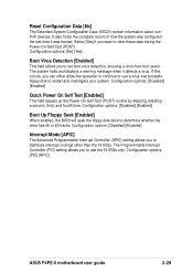
... configured the last time it detects a virus. Configuration options: [PIC] [APIC] ASUS P4PE-X motherboard user guide 2-29 Configuration options: [Disabled] [Enabled] Quick Power On Self Test [Enabled] This field speeds up the Power-On-Self Test (POST) routine by skipping retesting a second, third, and fourth ...[Disabled] [Enabled] Interrupt Mode [APIC] The Advanced Programmable Interrupt Controller (APIC) setting allows you to clear these data during the Power-On-Self-Test (POST). Select [Yes] if you to set boot virus detection, ensuring a virus-free boot sector. The Programmable...
... configured the last time it detects a virus. Configuration options: [PIC] [APIC] ASUS P4PE-X motherboard user guide 2-29 Configuration options: [Disabled] [Enabled] Quick Power On Self Test [Enabled] This field speeds up the Power-On-Self Test (POST) routine by skipping retesting a second, third, and fourth ...[Disabled] [Enabled] Interrupt Mode [APIC] The Advanced Programmable Interrupt Controller (APIC) setting allows you to clear these data during the Power-On-Self-Test (POST). Select [Yes] if you to set boot virus detection, ensuring a virus-free boot sector. The Programmable...


