
P4GE-V User Manual
Page 3
...ix ASUS contact information x P4GE-V ...specifications summary xi Chapter 1: Product introduction 1.1 Welcome 1-1 1.2 Package contents 1-1 1.3 Special features 1-2 1.4 Motherboard overview 1-6 1.4.1 Major components 1-6 1.4.2 Core specifications 1-8 Chapter 2: Hardware information 2.1 Motherboard installation 2-1 2.1.1 Placement direction 2-1 2.1.2 Screw holes 2-1 2.2 Motherboard layout 2-2 2.3 Before you proceed 2-3 2.4 Central Processing Unit (CPU 2-4 2.4.1 Overview 2-4 2.4.2 Installing the CPU 2-5 2.4.3 Installing the heatsink and fan 2-7 2.4.4 Connecting the CPU...
...ix ASUS contact information x P4GE-V ...specifications summary xi Chapter 1: Product introduction 1.1 Welcome 1-1 1.2 Package contents 1-1 1.3 Special features 1-2 1.4 Motherboard overview 1-6 1.4.1 Major components 1-6 1.4.2 Core specifications 1-8 Chapter 2: Hardware information 2.1 Motherboard installation 2-1 2.1.1 Placement direction 2-1 2.1.2 Screw holes 2-1 2.2 Motherboard layout 2-2 2.3 Before you proceed 2-3 2.4 Central Processing Unit (CPU 2-4 2.4.1 Overview 2-4 2.4.2 Installing the CPU 2-5 2.4.3 Installing the heatsink and fan 2-7 2.4.4 Connecting the CPU...

P4GE-V User Manual
Page 11
P4GE-V specifications summary CPU Chipset Front Side Bus (FSB) Memory Expansion slots VGA IDE Audio LAN Special features Rear panel I/O Socket 478 for Intel® Pentium® 4 / Celeron 3.0+ GHz.../33 connectors ADI AD1980 6-channel audio CODEC Broadcom® BCM4401 Fast Ethernet controller ASUS JumperFree™ mode ASUS POST Reporter™ ASUS EZ Plug™ ASUS Q-Fan ASUS EZ Flash C.P.R. (CPU Parameter Recall) CrashFree BIOS Power Loss Restart SFS (Stepless Frequency Selection) CPU throttle Adjustable CPU VCORE, memory, and AGP voltages Multi-language BIOS AGP warning LED 1 x ...
P4GE-V specifications summary CPU Chipset Front Side Bus (FSB) Memory Expansion slots VGA IDE Audio LAN Special features Rear panel I/O Socket 478 for Intel® Pentium® 4 / Celeron 3.0+ GHz.../33 connectors ADI AD1980 6-channel audio CODEC Broadcom® BCM4401 Fast Ethernet controller ASUS JumperFree™ mode ASUS POST Reporter™ ASUS EZ Plug™ ASUS Q-Fan ASUS EZ Flash C.P.R. (CPU Parameter Recall) CrashFree BIOS Power Loss Restart SFS (Stepless Frequency Selection) CPU throttle Adjustable CPU VCORE, memory, and AGP voltages Multi-language BIOS AGP warning LED 1 x ...

P4GE-V User Manual
Page 12
...9.0 in (30.5 cm x 22.9 cm) Device drivers ASUS PC Probe ASUS LiveUpdate Trend Micro™ PC-cillin 2002 anti-virus software * Specifications are subject to change without notice. xii P4GE-V specifications summary Internal I/O BIOS features Industry standard Manageability Form ...Factor Support CD contents 1 x USB 2.0/1.1 connector for 2 additional USB ports CPU...
...9.0 in (30.5 cm x 22.9 cm) Device drivers ASUS PC Probe ASUS LiveUpdate Trend Micro™ PC-cillin 2002 anti-virus software * Specifications are subject to change without notice. xii P4GE-V specifications summary Internal I/O BIOS features Industry standard Manageability Form ...Factor Support CD contents 1 x USB 2.0/1.1 connector for 2 additional USB ports CPU...
P4GE-V User Manual
Page 17
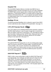
See page 1-9. eliminates the need to provide the additional power required by the P4 CPU. This connector is present. See pages 3-1, 4-25, and 5-17. See pages 2-15 and 4-22. See page 2-17. The ASUS EZ Plug™ is compliant with the Digital Visual Interface (DVI) Specification Rev. 1.0, and... high-speed interface to PCI specification. The bundled Winbond Voice Editor software allows you to overclocking. feature of boot errors, if any. ASUS P4GE-V motherboard user guide 1-3 The GMCH video engines support video conferencing and other video applications. BlueMagic PCI slot The...
See page 1-9. eliminates the need to provide the additional power required by the P4 CPU. This connector is present. See pages 3-1, 4-25, and 5-17. See pages 2-15 and 4-22. See page 2-17. The ASUS EZ Plug™ is compliant with the Digital Visual Interface (DVI) Specification Rev. 1.0, and... high-speed interface to PCI specification. The bundled Winbond Voice Editor software allows you to overclocking. feature of boot errors, if any. ASUS P4GE-V motherboard user guide 1-3 The GMCH video engines support video conferencing and other video applications. BlueMagic PCI slot The...

P4GE-V User Manual
Page 19
...ASUS P4GE-V motherboard user guide 1-5 See page 4-33. Chassis intrusion detection The motherboard supports chassis intrusion monitoring through the ASUS ASIC. The system voltage levels are monitored to prevent overheating and damage. A chassis intrusion event is retained in BIOS using the ASUS JumperFree™ solution • C.P.R. (CPU... Parameter Recall) • adjustable FSB/DDR ratio • Fixed AGP/PCI ratio • adjustable CPU VCORE , and DDR memory and AGP voltages ...
...ASUS P4GE-V motherboard user guide 1-5 See page 4-33. Chassis intrusion detection The motherboard supports chassis intrusion monitoring through the ASUS ASIC. The system voltage levels are monitored to prevent overheating and damage. A chassis intrusion event is retained in BIOS using the ASUS JumperFree™ solution • C.P.R. (CPU... Parameter Recall) • adjustable FSB/DDR ratio • Fixed AGP/PCI ratio • adjustable CPU VCORE , and DDR memory and AGP voltages ...

P4GE-V User Manual
Page 20
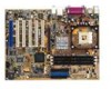
.... Refer to facilitate the motherboard installation and future upgrades. CPU socket 3. DDR DIMM sockets 5. Standby power LED 13. AGP slot 20. Parallel port 22. Microphone jack 26. Serial port 29. North Bridge controller 4. ASUS EZ Plug™ 12V connector 6. South Bridge controller 10.... PCI slots 16. A sufficient knowledge of the motherboard specifications will also help you install the P4GE-V motherboard, familiarize yourself with its components. 1.4.1 Major...
.... Refer to facilitate the motherboard installation and future upgrades. CPU socket 3. DDR DIMM sockets 5. Standby power LED 13. AGP slot 20. Parallel port 22. Microphone jack 26. Serial port 29. North Bridge controller 4. ASUS EZ Plug™ 12V connector 6. South Bridge controller 10.... PCI slots 16. A sufficient knowledge of the motherboard specifications will also help you install the P4GE-V motherboard, familiarize yourself with its components. 1.4.1 Major...

P4GE-V User Manual
Page 22
...Core specifications 1 ATX 12V connector. The GMCH interconnects to 2GB system memory using unbuffered non-ECC PC2700/ PC2100/PC1600 DDR DIMMs. 5 ASUS EZ Plug™ +12V connector. The ICH4 also contains the necessary arbitration and buffering for efficient utilization of the IDE ribbon cable....prevent incorrect insertion of these interfaces. 1-8 Chapter 1: Product introduction Connect a 4-pin device connector from the ATX 12V power supply. 2 CPU socket. Both the primary (blue) and secondary (black) connectors are slotted to six USB 2.0/1.1 ports, I /O functions including 2-channel...
...Core specifications 1 ATX 12V connector. The GMCH interconnects to 2GB system memory using unbuffered non-ECC PC2700/ PC2100/PC1600 DDR DIMMs. 5 ASUS EZ Plug™ +12V connector. The ICH4 also contains the necessary arbitration and buffering for efficient utilization of the IDE ribbon cable....prevent incorrect insertion of these interfaces. 1-8 Chapter 1: Product introduction Connect a 4-pin device connector from the ATX 12V power supply. 2 CPU socket. Both the primary (blue) and secondary (black) connectors are slotted to six USB 2.0/1.1 ports, I /O functions including 2-channel...

P4GE-V User Manual
Page 26
Chapter summary 2.1 Motherboard installation 2-1 2.2 Motherboard layout 2-2 2.3 Before you proceed 2-3 2.4 Central Processing Unit (CPU 2-4 2.5 System memory 2-10 2.6 Expansion slots 2-13 2.7 Jumpers 2-16 2.8 Connectors 2-18 ASUS P4GE-V motherboard
Chapter summary 2.1 Motherboard installation 2-1 2.2 Motherboard layout 2-2 2.3 Before you proceed 2-3 2.4 Central Processing Unit (CPU 2-4 2.5 System memory 2-10 2.6 Expansion slots 2-13 2.7 Jumpers 2-16 2.8 Connectors 2-18 ASUS P4GE-V motherboard

P4GE-V User Manual
Page 30
...3. Power up the system and enter BIOS Setup (see Chapter 4). This processor includes the Intel® NetBurst™ micro-architecture that the CPU has a gold triangular mark on one corner. Gold Mark Incorrect installation of 3.2GB/s and 4.2GB/s. For more information on 0.13 micron ... is supported under Windows XP and Linux 2.4.x (kernel) and later versions only. Buy an Intel Pentium 4 CPU that should match a specific corner of the CPU socket. Install the CPU. 2. Under the Advanced Menu, make sure that supports Hyper-Threading techonology. 2-4 Chapter 2: Hardware information The ...
...3. Power up the system and enter BIOS Setup (see Chapter 4). This processor includes the Intel® NetBurst™ micro-architecture that the CPU has a gold triangular mark on one corner. Gold Mark Incorrect installation of 3.2GB/s and 4.2GB/s. For more information on 0.13 micron ... is supported under Windows XP and Linux 2.4.x (kernel) and later versions only. Buy an Intel Pentium 4 CPU that should match a specific corner of the CPU socket. Install the CPU. 2. Under the Advanced Menu, make sure that supports Hyper-Threading techonology. 2-4 Chapter 2: Hardware information The ...

P4GE-V User Manual
Page 31
Locate the 478-pin ZIF socket on the motherboard. 2. Unlock the socket by pressing the lever sideways, then lift it up to 90°-100° angle, otherwise the CPU does not fit in completely. ASUS P4GE-V motherboard user guide 2-5 Socket Lever 90 - 100 Make sure that the socket lever is lifted up to install a CPU. 1. 2.4.2 Installing the CPU Follow these steps to a 90°-100° angle.
Locate the 478-pin ZIF socket on the motherboard. 2. Unlock the socket by pressing the lever sideways, then lift it up to 90°-100° angle, otherwise the CPU does not fit in completely. ASUS P4GE-V motherboard user guide 2-5 Socket Lever 90 - 100 Make sure that the socket lever is lifted up to install a CPU. 1. 2.4.2 Installing the CPU Follow these steps to a 90°-100° angle.

P4GE-V User Manual
Page 32
Position the CPU above the socket such that it fits in place. Carefully insert the CPU into the socket to prevent bending the pins and damaging the CPU! The CPU fits only in place, push down the socket lever to indicate that its marked corner matches the base of the socket lever. 4. DO NOT force the CPU into the socket until it is in one correct orientation. Gold Mark 5. The lever clicks on the side tab to secure the CPU. 3. When the CPU is locked. 2-6 Chapter 2: Hardware information
Position the CPU above the socket such that it fits in place. Carefully insert the CPU into the socket to prevent bending the pins and damaging the CPU! The CPU fits only in place, push down the socket lever to indicate that its marked corner matches the base of the socket lever. 4. DO NOT force the CPU into the socket until it is in one correct orientation. Gold Mark 5. The lever clicks on the side tab to secure the CPU. 3. When the CPU is locked. 2-6 Chapter 2: Hardware information

P4GE-V User Manual
Page 33
...and fan The Intel® Pentium® 4 Processor requires a specially designed heatsink and fan assembly to install the CPU heatsink and fan. 1. Follow these steps to ensure optimum thermal condition and performance. If the instructions in this section...Processor, the package includes the heatsink, fan, and retention mechanism. CPU Heatsink Retention Module Base Your boxed Intel Pentium 4 Processor package should come with installation instructions for the CPU, heatsink, and the retention mechanism. ASUS P4GE-V motherboard user guide 2-7 The retention module base is already installed ...
...and fan The Intel® Pentium® 4 Processor requires a specially designed heatsink and fan assembly to install the CPU heatsink and fan. 1. Follow these steps to ensure optimum thermal condition and performance. If the instructions in this section...Processor, the package includes the heatsink, fan, and retention mechanism. CPU Heatsink Retention Module Base Your boxed Intel Pentium 4 Processor package should come with installation instructions for the CPU, heatsink, and the retention mechanism. ASUS P4GE-V motherboard user guide 2-7 The retention module base is already installed ...

P4GE-V User Manual
Page 35
Push down the locks on the motherboard labeled CPU_FAN1. Hardware monitoring errors may occur if you fail to connect the CPU fan connector! ASUS P4GE-V motherboard user guide 2-9 3. CPU Fan Connector (CPU_FAN1) Don't forget to plug this connector. When secure, the retention locks should point to opposite directions. 2.4.4 Connecting the CPU fan cable When the fan, heatsink, and the retention mechanism are in place, connect the CPU fan cable to the connector on the retention mechanism to secure the heatsink and fan to the module base.
Push down the locks on the motherboard labeled CPU_FAN1. Hardware monitoring errors may occur if you fail to connect the CPU fan connector! ASUS P4GE-V motherboard user guide 2-9 3. CPU Fan Connector (CPU_FAN1) Don't forget to plug this connector. When secure, the retention locks should point to opposite directions. 2.4.4 Connecting the CPU fan cable When the fan, heatsink, and the retention mechanism are in place, connect the CPU fan cable to the connector on the retention mechanism to secure the heatsink and fan to the module base.

P4GE-V User Manual
Page 36
... 2.5.1 Overview The motherboard comes with SDR, and should be installed only in one clock cycle, thus providing twice the throughput of the SDR DIMM. CPU FSB 533 MHz 400 MHz DDR DIMM Type PC2700 PC2100 PC2100 PC1600 Memory Frequency 333 MHz 266 MHz 266 MHz 200 MHz Notes on DDR...it has a 184-pin footprint compared to 2GB system memory using 184-pin unbuffered non-ECC PC2700/PC2100/ PC1600 DDR DIMMs. ® P4GE-V 80 Pins 104 Pins P4GE-V 184-Pin DDR DIMM Sockets This motherboard supports different memory frequencies depending on the CPU FSB (Front Side Bus) and the type of DDR DIMM.
... 2.5.1 Overview The motherboard comes with SDR, and should be installed only in one clock cycle, thus providing twice the throughput of the SDR DIMM. CPU FSB 533 MHz 400 MHz DDR DIMM Type PC2700 PC2100 PC2100 PC1600 Memory Frequency 333 MHz 266 MHz 266 MHz 200 MHz Notes on DDR...it has a 184-pin footprint compared to 2GB system memory using 184-pin unbuffered non-ECC PC2700/PC2100/ PC1600 DDR DIMMs. ® P4GE-V 80 Pins 104 Pins P4GE-V 184-Pin DDR DIMM Sockets This motherboard supports different memory frequencies depending on the CPU FSB (Front Side Bus) and the type of DDR DIMM.
P4GE-V User Manual
Page 43
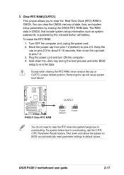
... You can automatically reset parameter settings to pins 1-2. 3. For system failure due to overclocking. ASUS P4GE-V motherboard user guide 2-17 Removing the cap will cause system boot failure! ® P4GE-V P4GE-V Clear RTC RAM CLRTC1 12 23 Disable (Default) Enable You do not need to clear the... RTC when the system hangs due to overclocking, use the C.P.R. (CPU Parameter Recall) feature. Move the jumper cap from pins ...
... You can automatically reset parameter settings to pins 1-2. 3. For system failure due to overclocking. ASUS P4GE-V motherboard user guide 2-17 Removing the cap will cause system boot failure! ® P4GE-V P4GE-V Clear RTC RAM CLRTC1 12 23 Disable (Default) Enable You do not need to clear the... RTC when the system hangs due to overclocking, use the C.P.R. (CPU Parameter Recall) feature. Move the jumper cap from pins ...

P4GE-V User Manual
Page 47
... to the CPU. The minimum recommended wattage is inadequate. ® P4GE-V ATXPWR1 EZ_PLUG1 Pin 1 +12.0VDC +5VSB PWR_OK GND +5.0VDC GND +5.0VDC GND +3.3VDC +3.3VDC +5.0VDC +5.0VDC -5.0VDC +12V GND GND +5V GND GND GND PS_ON# GND ATX12V1 -12.0VDC +3.3VDC +12V DC +12V DC GND GND P4GE-V ATX & Auxiliary Power Connectors ASUS P4GE-V motherboard...
... to the CPU. The minimum recommended wattage is inadequate. ® P4GE-V ATXPWR1 EZ_PLUG1 Pin 1 +12.0VDC +5VSB PWR_OK GND +5.0VDC GND +5.0VDC GND +3.3VDC +3.3VDC +5.0VDC +5.0VDC -5.0VDC +12V GND GND +5V GND GND GND PS_ON# GND ATX12V1 -12.0VDC +3.3VDC +12V DC +12V DC GND GND P4GE-V ATX & Auxiliary Power Connectors ASUS P4GE-V motherboard...

P4GE-V User Manual
Page 48
CPU, Chassis, and Power Fan Connectors (3-pin CPU_FAN1, PWR_FAN1, CHA_FAN1) The fan connectors... cable matches the ground pin of the connector. CPU_FAN1 GND +12V Rotation CHA_FAN1 PWR_FAN1 ® P4GE-V Rotation +12V GND GND +12V Rotation P4GE-V 12-Volt Fan Connectors 8. Power supply thermal connector (2-pin TRPWR1) If your power supply has... the fan connectors on the fan connectors! Connect the fan cables to this connector. ® P4GE-V TRPWR1 Ground TRPWR P4GE-V Power Supply Thermal Connector 2-22 Chapter 2: Hardware information Do not forget to connect the fan cables to the...
CPU, Chassis, and Power Fan Connectors (3-pin CPU_FAN1, PWR_FAN1, CHA_FAN1) The fan connectors... cable matches the ground pin of the connector. CPU_FAN1 GND +12V Rotation CHA_FAN1 PWR_FAN1 ® P4GE-V Rotation +12V GND GND +12V Rotation P4GE-V 12-Volt Fan Connectors 8. Power supply thermal connector (2-pin TRPWR1) If your power supply has... the fan connectors on the fan connectors! Connect the fan cables to this connector. ® P4GE-V TRPWR1 Ground TRPWR P4GE-V Power Supply Thermal Connector 2-22 Chapter 2: Hardware information Do not forget to connect the fan cables to the...

P4GE-V User Manual
Page 57
...the power connector at a lower frequency You will hear the vocal POST messages instead. 7. While the tests are running at the back of the chassis). 6. ASUS P4GE-V motherboard user guide 3-1 Turn on the front of the system chassis. 4. Monitor b. At power on, hold down to switch on the power supply as ... not see anything within 30 seconds from the time you press the ATX power switch. You will not hear the BIOS beeps when the ASUS POST Reporter™ is working Meaning No error during POST No DRAM installed or detected Video card not found or video card memory bad...
...the power connector at a lower frequency You will hear the vocal POST messages instead. 7. While the tests are running at the back of the chassis). 6. ASUS P4GE-V motherboard user guide 3-1 Turn on the front of the system chassis. 4. Monitor b. At power on, hold down to switch on the power supply as ... not see anything within 30 seconds from the time you press the ATX power switch. You will not hear the BIOS beeps when the ASUS POST Reporter™ is working Meaning No error during POST No DRAM installed or detected Video card not found or video card memory bad...
P4GE-V User Manual
Page 58
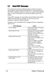
...set to inform you will hear the specific cause of the PCI slots, or a 1.5V AGP card into the CPU socket. • Check the CPU if properly installed. • Call ASUS technical support for instruction on installing a DIMM. • Install a PCI VGA card into one of the problem...JumperFree mode, check your own messages to support a special feature called the ASUS POST Reporter™. POST Message No CPU installed System failed CPU test System failed memory test System failed VGA test System failed due to CPU over-clocking Action • Install an Intel Pentium 4 Processor into the ...
...set to inform you will hear the specific cause of the PCI slots, or a 1.5V AGP card into the CPU socket. • Check the CPU if properly installed. • Call ASUS technical support for instruction on installing a DIMM. • Install a PCI VGA card into one of the problem...JumperFree mode, check your own messages to support a special feature called the ASUS POST Reporter™. POST Message No CPU installed System failed CPU test System failed memory test System failed VGA test System failed due to CPU over-clocking Action • Install an Intel Pentium 4 Processor into the ...

P4GE-V User Manual
Page 59
... • Check your keyboard if properly connected to the system. • Make sure that your CPU fan supports the fan speed detection function. See section "4.4.2 I/O Device Configuration". ASUS P4GE-V motherboard user guide 3-3 CPU temperature too high • Check CPU fan if working properly. System completed Power-On Self Test • No action required Computer now...
... • Check your keyboard if properly connected to the system. • Make sure that your CPU fan supports the fan speed detection function. See section "4.4.2 I/O Device Configuration". ASUS P4GE-V motherboard user guide 3-3 CPU temperature too high • Check CPU fan if working properly. System completed Power-On Self Test • No action required Computer now...


