
Motherboard DIY Troubleshooting Guide
Page 39
SW1 ® ON 12345 ON 12345 ON 12345 ON 12345 ON 12345 CPU 100MHz 103MHz 105MHz 107MHz 109MHz AGP 66MHz 68MHz 70MHz 71MHz 72MHz PCI 33MHz 34MHz 35MHz 35MHz 36MHz ON 12345 ON 12345 ON 12345 ON 12345 ON 12345 ON 12345 P4BGL-VM CPU 111MHz 114MHz 120MHz 125MHz 133MHz 135MHz AGP 74MHz 76MHz 60MHz 62MHz 66MHz 67MHz P4BGL-VM CPU PCI 37MHz 38MHz 30MHz 31MHz 33MHz 33MHz External Frequency Selection ® P4BGL-VM KBPWR 1 2 +5V 2 3 +5VSB (Default) P4BGL-VM Keyboard Power Setting 2-17
SW1 ® ON 12345 ON 12345 ON 12345 ON 12345 ON 12345 CPU 100MHz 103MHz 105MHz 107MHz 109MHz AGP 66MHz 68MHz 70MHz 71MHz 72MHz PCI 33MHz 34MHz 35MHz 35MHz 36MHz ON 12345 ON 12345 ON 12345 ON 12345 ON 12345 ON 12345 P4BGL-VM CPU 111MHz 114MHz 120MHz 125MHz 133MHz 135MHz AGP 74MHz 76MHz 60MHz 62MHz 66MHz 67MHz P4BGL-VM CPU PCI 37MHz 38MHz 30MHz 31MHz 33MHz 33MHz External Frequency Selection ® P4BGL-VM KBPWR 1 2 +5V 2 3 +5VSB (Default) P4BGL-VM Keyboard Power Setting 2-17

P4BGL-VM User Manual
Page 3
...viii How this guide is organized viii Conventions used in this guide ix Where to find more information ix ASUS contact information x P4BGL-VM specifications summary xi Chapter 1: Product introduction 1.1 Welcome 1-1 1.2 Package contents 1-1 1.3 Special features 1-2 ...Screw holes 2-1 2.2 Motherboard layout 2-2 2.3 Before you proceed 2-3 2.4 Central Processing Unit (CPU 2-4 2.4.1 Overview 2-4 2.4.2 Installing the CPU 2-5 2.4.3 Installing the heatsink and fan 2-7 2.4.4 Connecting the CPU fan cable 2-9 2.5 System memory 2-10 2.5.1 Overview 2-10 2.5.2 Memory configurations 2-11 ...
...viii How this guide is organized viii Conventions used in this guide ix Where to find more information ix ASUS contact information x P4BGL-VM specifications summary xi Chapter 1: Product introduction 1.1 Welcome 1-1 1.2 Package contents 1-1 1.3 Special features 1-2 ...Screw holes 2-1 2.2 Motherboard layout 2-2 2.3 Before you proceed 2-3 2.4 Central Processing Unit (CPU 2-4 2.4.1 Overview 2-4 2.4.2 Installing the CPU 2-5 2.4.3 Installing the heatsink and fan 2-7 2.4.4 Connecting the CPU fan cable 2-9 2.5 System memory 2-10 2.5.1 Overview 2-10 2.5.2 Memory configurations 2-11 ...
P4BGL-VM User Manual
Page 17
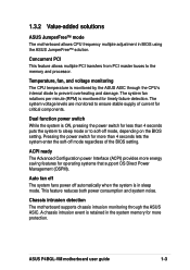
... less than 4 seconds lets the system enter the soft-off mode regardless of current for critical components. 1.3.2 Value-added solutions ASUS JumperFree™ mode The motherboard allows CPU frequency multiple adjustment in the system memory for more protection. ASUS P4BGL-VM motherboard user guide 1-3 The system fan rotations per minute (RPM) is monitored by the...
... less than 4 seconds lets the system enter the soft-off mode regardless of current for critical components. 1.3.2 Value-added solutions ASUS JumperFree™ mode The motherboard allows CPU frequency multiple adjustment in the system memory for more protection. ASUS P4BGL-VM motherboard user guide 1-3 The system fan rotations per minute (RPM) is monitored by the...

P4BGL-VM User Manual
Page 18
... knowledge of the motherboard specifications will also help you install the P4BGL-VM motherboard, familiarize yourself with its components. 1.4.1 Major components The following are the major components of each component. ATX power connector 7. ASUS ASIC 13. Parallel port 19. Line Out jack (optional) ...22. Keyboard port See page 1-6 for detailed information on page 1-5. 1. ATX 12V connector 3. CPU socket 4. PS/2 mouse port 18. USB 2.0 ports 3 ...
... knowledge of the motherboard specifications will also help you install the P4BGL-VM motherboard, familiarize yourself with its components. 1.4.1 Major components The following are the major components of each component. ATX power connector 7. ASUS ASIC 13. Parallel port 19. Line Out jack (optional) ...22. Keyboard port See page 1-6 for detailed information on page 1-5. 1. ATX 12V connector 3. CPU socket 4. PS/2 mouse port 18. USB 2.0 ports 3 ...
P4BGL-VM User Manual
Page 20
...controller. This Low Pin Count (LPC) interface provides the commonly used Super I /O controller. This 20-pin connector connects to set the CPU external frequency. 2 ATX 12V connector. These dual-channel bus master IDE connectors support up to prevent incorrect insertion of the IDE ribbon ...A 478-pin surface mount, Zero Insertion Force (ZIF) socket for the 4-pin 12V plug from an ATX 12V power supply. 3 CPU socket. 1.4.2 Core specifications 1 DIP switches. The integrated graphics accelerator delivers 3D/2D video capabilities and a high bandwidth access to prevent incorrect...
...controller. This Low Pin Count (LPC) interface provides the commonly used Super I /O controller. This 20-pin connector connects to set the CPU external frequency. 2 ATX 12V connector. These dual-channel bus master IDE connectors support up to prevent incorrect insertion of the IDE ribbon ...A 478-pin surface mount, Zero Insertion Force (ZIF) socket for the 4-pin 12V plug from an ATX 12V power supply. 3 CPU socket. 1.4.2 Core specifications 1 DIP switches. The integrated graphics accelerator delivers 3D/2D video capabilities and a high bandwidth access to prevent incorrect...

P4BGL-VM User Manual
Page 24
Chapter summary 2.1 Motherboard installation 2-1 2.2 Motherboard layout 2-2 2.3 Before you proceed 2-3 2.4 Central Processing Unit (CPU 2-4 2.5 System memory 2-10 2.6 Expansion slots 2-13 2.7 Switches and jumpers 2-16 2.8 Connectors 2-20 ASUS P4BGL-VM motherboard
Chapter summary 2.1 Motherboard installation 2-1 2.2 Motherboard layout 2-2 2.3 Before you proceed 2-3 2.4 Central Processing Unit (CPU 2-4 2.5 System memory 2-10 2.6 Expansion slots 2-13 2.7 Switches and jumpers 2-16 2.8 Connectors 2-20 ASUS P4BGL-VM motherboard

P4BGL-VM User Manual
Page 28
... 2: Hardware information This processor includes the Intel® NetBurst™ micro-architecture that the CPU has a gold triangular mark on 0.13 micron process. Incorrect installation of the CPU socket. The socket is designed for the Intel Pentium 4 Processor in the illustration that features... the hyper-pipelined technology, rapid execution engine, 533/400MHz system bus, and execution trace cache. 2.4 Central Processing Unit (CPU) 2.4.1 Overview The motherboard comes with 512KB L2 cache on one corner. Gold Mark Note in the 478-pin package with a surface...
... 2: Hardware information This processor includes the Intel® NetBurst™ micro-architecture that the CPU has a gold triangular mark on 0.13 micron process. Incorrect installation of the CPU socket. The socket is designed for the Intel Pentium 4 Processor in the illustration that features... the hyper-pipelined technology, rapid execution engine, 533/400MHz system bus, and execution trace cache. 2.4 Central Processing Unit (CPU) 2.4.1 Overview The motherboard comes with 512KB L2 cache on one corner. Gold Mark Note in the 478-pin package with a surface...

P4BGL-VM User Manual
Page 29
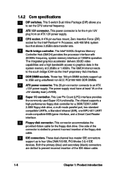
Unlock the socket by pressing the lever sideways, then lift it up to 90°-100° angle, otherwise the CPU does not fit in completely. Socket Lever 90 - 100 Make sure that the socket lever is lifted up to install a CPU. 1. 2.4.2 Installing the CPU Follow these steps to a 90°-100° angle. Locate the 478-pin ZIF socket on the motherboard. 2. ASUS P4BGL-VM motherboard user guide 2-5
Unlock the socket by pressing the lever sideways, then lift it up to 90°-100° angle, otherwise the CPU does not fit in completely. Socket Lever 90 - 100 Make sure that the socket lever is lifted up to install a CPU. 1. 2.4.2 Installing the CPU Follow these steps to a 90°-100° angle. Locate the 478-pin ZIF socket on the motherboard. 2. ASUS P4BGL-VM motherboard user guide 2-5

P4BGL-VM User Manual
Page 30
When the CPU is locked. 2-6 Chapter 2: Hardware information Position the CPU above the socket such that it firmly on the side tab to prevent bending the pins and damaging the CPU! Carefully insert the CPU into the socket to indicate that its marked corner matches the base of the socket lever. 4. Gold Mark 5. The lever clicks on the socket while you push down the socket lever to secure the CPU. The CPU fits only in one correct orientation. DO NOT force the CPU into the socket until it fits in place, press it is in place. 3.
When the CPU is locked. 2-6 Chapter 2: Hardware information Position the CPU above the socket such that it firmly on the side tab to prevent bending the pins and damaging the CPU! Carefully insert the CPU into the socket to indicate that its marked corner matches the base of the socket lever. 4. Gold Mark 5. The lever clicks on the socket while you push down the socket lever to secure the CPU. The CPU fits only in one correct orientation. DO NOT force the CPU into the socket until it fits in place, press it is in place. 3.

P4BGL-VM User Manual
Page 31
... this section do not have to ensure optimum thermal condition and performance. You do not match the CPU documentation, follow the latter. The retention module base is already installed on the retention module base. ASUS P4BGL-VM motherboard user guide 2-7 2.4.3 Installing the heatsink and fan The Intel® Pentium® 4 Processor requires a specially designed...
... this section do not have to ensure optimum thermal condition and performance. You do not match the CPU documentation, follow the latter. The retention module base is already installed on the retention module base. ASUS P4BGL-VM motherboard user guide 2-7 2.4.3 Installing the heatsink and fan The Intel® Pentium® 4 Processor requires a specially designed...
P4BGL-VM User Manual
Page 33
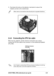
When secure, the retention locks should point to opposite directions. 2.4.4 Connecting the CPU fan cable When the fan, heatsink, and the retention mechanism are in place, connect the CPU fan cable to the connector on the retention mechanism to secure the heatsink and fan to the module base. CPU Fan Connector (CPU_FAN1) Don't forget to plug this connector. Hardware monitoring errors may occur if you fail to connect the CPU fan connector! 3. Push down the locks on the motherboard labeled CPU_FAN. ASUS P4BGL-VM motherboard user guide 2-9
When secure, the retention locks should point to opposite directions. 2.4.4 Connecting the CPU fan cable When the fan, heatsink, and the retention mechanism are in place, connect the CPU fan cable to the connector on the retention mechanism to secure the heatsink and fan to the module base. CPU Fan Connector (CPU_FAN1) Don't forget to plug this connector. Hardware monitoring errors may occur if you fail to connect the CPU fan connector! 3. Push down the locks on the motherboard labeled CPU_FAN. ASUS P4BGL-VM motherboard user guide 2-9
P4BGL-VM User Manual
Page 40
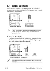
... DIP switches. The JumperFree mode allows you wish to the CPU frequency switch settings on the next page. 2-16 Chapter 2: Hardware information J6 ® ON OFF SW1 ON 12345 P4BGL-VM 12 Jumper Free (Default) P4BGL-VM JumperFree™ Mode Setting 23 Jumper Mode For jumper mode,... to use the DIP switches. The illustration below shows all the switches in the ON position. ® SW1 ON 12345 ON OFF P4BGL-VM P4BGL-VM DIP Switches 1.Frequency Selection 2.Frequency Selection 3.Frequency Selection 4.Frequency Selection 5.Frequency Selection The J6 jumper must be set to pins 2-3 (...
... DIP switches. The JumperFree mode allows you wish to the CPU frequency switch settings on the next page. 2-16 Chapter 2: Hardware information J6 ® ON OFF SW1 ON 12345 P4BGL-VM 12 Jumper Free (Default) P4BGL-VM JumperFree™ Mode Setting 23 Jumper Mode For jumper mode,... to use the DIP switches. The illustration below shows all the switches in the ON position. ® SW1 ON 12345 ON OFF P4BGL-VM P4BGL-VM DIP Switches 1.Frequency Selection 2.Frequency Selection 3.Frequency Selection 4.Frequency Selection 5.Frequency Selection The J6 jumper must be set to pins 2-3 (...
P4BGL-VM User Manual
Page 41
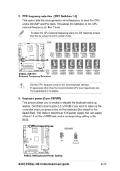
...ON 12345 ON 12345 ON 12345 ON 12345 P4BGL-VM CPU 111MHz 114MHz 120MHz 125MHz 133MHz 135MHz AGP 74MHz 76MHz 60MHz 62MHz 66MHz 67MHz P4BGL-VM CPU PCI 37MHz 38MHz 30MHz 31MHz 33MHz 33MHz External Frequency Selection Set the CPU frequency only to enable or disable the ... (+5VSB) if you press a key on the +5VSB lead, and a corresponding setting in the BIOS. ® P4BGL-VM KBPWR 1 2 +5V 2 3 +5VSB (Default) P4BGL-VM Keyboard Power Setting ASUS P4BGL-VM motherboard user guide 2-17 CPU frequency selection (SW1 Switches 1-5) This option tells the clock generator what frequency to send the...
...ON 12345 ON 12345 ON 12345 ON 12345 P4BGL-VM CPU 111MHz 114MHz 120MHz 125MHz 133MHz 135MHz AGP 74MHz 76MHz 60MHz 62MHz 66MHz 67MHz P4BGL-VM CPU PCI 37MHz 38MHz 30MHz 31MHz 33MHz 33MHz External Frequency Selection Set the CPU frequency only to enable or disable the ... (+5VSB) if you press a key on the +5VSB lead, and a corresponding setting in the BIOS. ® P4BGL-VM KBPWR 1 2 +5V 2 3 +5VSB (Default) P4BGL-VM Keyboard Power Setting ASUS P4BGL-VM motherboard user guide 2-17 CPU frequency selection (SW1 Switches 1-5) This option tells the clock generator what frequency to send the...

P4BGL-VM User Manual
Page 42
..., DRAM refreshed, system running in reduced power mode). Otherwise, the system does not power up the computer from S3 sleep mode (no power to CPU, DRAM in slow refresh, power supply in low power mode) using the connected USB devices. 4. Set to +5VSB to wake up (3-pin USBPWR1, USBPWR2, USBPWR3)...to support this feature. The total current consumed must NOT exceed the power supply capability (+5VSB) whether under normal condition or in sleep mode. ® P4BGL-VM USBPWR2 USBPWR1 USBPWR3 12 23 +5V (Default) +5VSB P4BGL-VM USB Device Wake Up 2-18 Chapter 2: Hardware information
..., DRAM refreshed, system running in reduced power mode). Otherwise, the system does not power up the computer from S3 sleep mode (no power to CPU, DRAM in slow refresh, power supply in low power mode) using the connected USB devices. 4. Set to +5VSB to wake up (3-pin USBPWR1, USBPWR2, USBPWR3)...to support this feature. The total current consumed must NOT exceed the power supply capability (+5VSB) whether under normal condition or in sleep mode. ® P4BGL-VM USBPWR2 USBPWR1 USBPWR3 12 23 +5V (Default) +5VSB P4BGL-VM USB Device Wake Up 2-18 Chapter 2: Hardware information

P4BGL-VM User Manual
Page 46
...). Find the proper orientation and push down firmly until the connectors completely fit. The plugs from the power supply are designed to the CPU. ATX power connectors (20-pin ATX_POWER1, 4-pin ATX12V) These connectors connect to an ATX 12V power supply. Make sure that you ... to provide sufficient power to fit these connectors in only one orientation. The minimum recommended wattage is inadequate. ® ATX_POWER1 P4BGL-VM ATX12V +12V DC GND +12V DC GND P4BGL-VM ATX Power Connectors Pin 1 +12.0VDC +5VSB PWR_OK COM +5.0VDC COM +5.0VDC COM +3.3VDC +3.3VDC +5.0VDC +5.0VDC ...
...). Find the proper orientation and push down firmly until the connectors completely fit. The plugs from the power supply are designed to the CPU. ATX power connectors (20-pin ATX_POWER1, 4-pin ATX12V) These connectors connect to an ATX 12V power supply. Make sure that you ... to provide sufficient power to fit these connectors in only one orientation. The minimum recommended wattage is inadequate. ® ATX_POWER1 P4BGL-VM ATX12V +12V DC GND +12V DC GND P4BGL-VM ATX Power Connectors Pin 1 +12.0VDC +5VSB PWR_OK COM +5.0VDC COM +5.0VDC COM +3.3VDC +3.3VDC +5.0VDC +5.0VDC ...
P4BGL-VM User Manual
Page 47
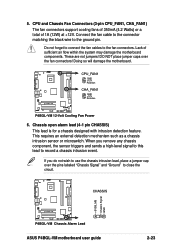
... triggers and sends a high-level signal to this lead to close the circuit. ® CHASSIS +5VSB_MB Chassis Signal GND P4BGL-VM P4BGL-VM Chassis Alarm Lead ASUS P4BGL-VM motherboard user guide 2-23 DO NOT place jumper caps over the pins labeled "Chassis Signal" and "Ground" to record a...connect the fan cables to the ground pin. Doing so will damage the motherboard. ® P4BGL-VM CPU_FAN1 GND +12V Rotation CHA_FAN1 GND +12V Rotation P4BGL-VM 12-Volt Cooling Fan Power 6. CPU and Chassis Fan Connectors (3-pin CPU_FAN1, CHA_FAN1) The fan connectors support cooling fans of 350mA ...
... triggers and sends a high-level signal to this lead to close the circuit. ® CHASSIS +5VSB_MB Chassis Signal GND P4BGL-VM P4BGL-VM Chassis Alarm Lead ASUS P4BGL-VM motherboard user guide 2-23 DO NOT place jumper caps over the pins labeled "Chassis Signal" and "Ground" to record a...connect the fan cables to the ground pin. Doing so will damage the motherboard. ® P4BGL-VM CPU_FAN1 GND +12V Rotation CHA_FAN1 GND +12V Rotation P4BGL-VM 12-Volt Cooling Fan Power 6. CPU and Chassis Fan Connectors (3-pin CPU_FAN1, CHA_FAN1) The fan connectors support cooling fans of 350mA ...
P4BGL-VM User Manual
Page 57
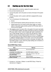
... power, the power LED on the system front panel case lights up or switch between orange and green after the system LED turns on test. ASUS P4BGL-VM motherboard user guide 3-1 Monitor b. At power on tests. Follow the instructions in an endless loop One long beep followed by three short beeps High frequency...-on . Be sure that is working Meaning No error during POST No DRAM installed or detected Video card not found or video card memory bad CPU overheated; After making all switches are off. 3. Connect the power cord to switch on the power supply as well as press the ATX power ...
... power, the power LED on the system front panel case lights up or switch between orange and green after the system LED turns on test. ASUS P4BGL-VM motherboard user guide 3-1 Monitor b. At power on tests. Follow the instructions in an endless loop One long beep followed by three short beeps High frequency...-on . Be sure that is working Meaning No error during POST No DRAM installed or detected Video card not found or video card memory bad CPU overheated; After making all switches are off. 3. Connect the power cord to switch on the power supply as well as press the ATX power ...

P4BGL-VM User Manual
Page 77
...to be in synchronous or asynchronous mode with CPU Frequency (MHz) to change the setting of this item. Configuration options: [Auto] [1:1] [3:4] ASUS P4BGL-VM motherboard user guide 4-17 Select [Manual] if you want to match the speed of the CPU. The bus frequency (external frequency) multiplied ...by the bus multiple equals the CPU speed. Set this field in the popup menu vary ...
...to be in synchronous or asynchronous mode with CPU Frequency (MHz) to change the setting of this item. Configuration options: [Auto] [1:1] [3:4] ASUS P4BGL-VM motherboard user guide 4-17 Select [Manual] if you want to match the speed of the CPU. The bus frequency (external frequency) multiplied ...by the bus multiple equals the CPU speed. Set this field in the popup menu vary ...

P4BGL-VM User Manual
Page 78
... used for expansion cards. The default of greater than 64MB, you need to set to [Enabled], the BIOS loads the update on or off the CPU Level 1 and Level 2 built-in cache. Configuration options: [Disabled] [Enabled] 4-18 Chapter 4: BIOS Setup If not detected, the USB controller legacy ...mode is disabled whether or not you are using OS/2 operating systems with the required data. CPU Level 1 Cache, CPU Level 2 Cache [Enabled] These fields allow you to choose from the default [Enabled] or choose [Disabled] to turn on all processors ...
... used for expansion cards. The default of greater than 64MB, you need to set to [Enabled], the BIOS loads the update on or off the CPU Level 1 and Level 2 built-in cache. Configuration options: [Disabled] [Enabled] 4-18 Chapter 4: BIOS Setup If not detected, the USB controller legacy ...mode is disabled whether or not you are using OS/2 operating systems with the required data. CPU Level 1 Cache, CPU Level 2 Cache [Enabled] These fields allow you to choose from the default [Enabled] or choose [Disabled] to turn on all processors ...
P4BGL-VM User Manual
Page 81
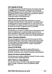
... the system may keep the default [4X Mode] even if you may not boot. Set this feature frees the PCI bus when the CPU is accessing 8-bit ISA cards. Configuration options: [1X Mode] [4X Mode] Video Memory Cache Mode [UC] USWC (uncacheable, speculative write... provides a peak data throughput of the USB 2.0 high-speed drive strength reference voltage. Configuration options: [Low] [Medium] [High] [Maximum] ASUS P4BGL-VM motherboard user guide 4-21 You must set both . Expansion cards can only access memory up to [Disabled]. This process normally consumes about 50-60...
... the system may keep the default [4X Mode] even if you may not boot. Set this feature frees the PCI bus when the CPU is accessing 8-bit ISA cards. Configuration options: [1X Mode] [4X Mode] Video Memory Cache Mode [UC] USWC (uncacheable, speculative write... provides a peak data throughput of the USB 2.0 high-speed drive strength reference voltage. Configuration options: [Low] [Medium] [High] [Maximum] ASUS P4BGL-VM motherboard user guide 4-21 You must set both . Expansion cards can only access memory up to [Disabled]. This process normally consumes about 50-60...


