Motherboard DIY Troubleshooting Guide
Page 1
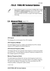
... External Frequency (MHz) This feature tells the clock generator what frequency to send to 533MHz FSB. Technical Updates P4BGL-MX Motherboard IE1154B P4BGL-MX Technical Updates • This motherboard supports overclocking to the system bus and PCI bus. CPU Frequency Multiple This field displays frequency multiple value between ... (page 2-14) CPU Speed This displays the current speed of the CPU installed. Configuration options: [Auto] 15-060174002 ASUS P4BGL-MX Technical Updates 1 To adjust CPU Speed and Memory Frequency, enter the BIOS Setup Utility and select the Advanced Menu.
... External Frequency (MHz) This feature tells the clock generator what frequency to send to 533MHz FSB. Technical Updates P4BGL-MX Motherboard IE1154B P4BGL-MX Technical Updates • This motherboard supports overclocking to the system bus and PCI bus. CPU Frequency Multiple This field displays frequency multiple value between ... (page 2-14) CPU Speed This displays the current speed of the CPU installed. Configuration options: [Auto] 15-060174002 ASUS P4BGL-MX Technical Updates 1 To adjust CPU Speed and Memory Frequency, enter the BIOS Setup Utility and select the Advanced Menu.

P4BGL-MX/533 User Manual
Page 1
Motherboard P4BGL-MX User Guide
Motherboard P4BGL-MX User Guide
P4BGL-MX/533 User Manual
Page 3
BIOS Information 2-1 2.1 Managing and updating your BIOS 2-2 2.1.1 Using ASUS EZ FLASH to update the BIOS 2-2 2.1.2 Using ASUS AFLASH to find more information vii ASUS contact information vii Specifications summary ix Chapter 1 - Motherboard Info 1-1 1.1 Welcome 1-2 1.2 Package contents 1-2 1.3 Introduction 1-3 1.4 Motherboard components 1-3 1.5 Motherboard layout 1-6 1.6 Before you proceed 1-7 1.7 Central Processing Unit (CPU 1-7 1.8 System memory 1-8 1.9 Expansion Slots 1-9 1.9.1 Configuring an expansion card 1-9 1.9.2 Standard...
BIOS Information 2-1 2.1 Managing and updating your BIOS 2-2 2.1.1 Using ASUS EZ FLASH to update the BIOS 2-2 2.1.2 Using ASUS AFLASH to find more information vii ASUS contact information vii Specifications summary ix Chapter 1 - Motherboard Info 1-1 1.1 Welcome 1-2 1.2 Package contents 1-2 1.3 Introduction 1-3 1.4 Motherboard components 1-3 1.5 Motherboard layout 1-6 1.6 Before you proceed 1-7 1.7 Central Processing Unit (CPU 1-7 1.8 System memory 1-8 1.9 Expansion Slots 1-9 1.9.1 Configuring an expansion card 1-9 1.9.2 Standard...
P4BGL-MX/533 User Manual
Page 6
... supply is broken, do not try to the correct voltage in any damage, contact your retailer. vi Operation safety • Before installing the motherboard and adding devices on a stable surface. • If you add a device. • Before connecting or removing signal cables from the... motherboard, ensure that came with the product, contact a qualified service technician or your dealer immediately. • To avoid short circuits, keep paper clips, screws,...
... supply is broken, do not try to the correct voltage in any damage, contact your retailer. vi Operation safety • Before installing the motherboard and adding devices on a stable surface. • If you add a device. • Before connecting or removing signal cables from the... motherboard, ensure that came with the product, contact a qualified service technician or your dealer immediately. • To avoid short circuits, keep paper clips, screws,...
P4BGL-MX/533 User Manual
Page 11
Motherboard Info ASUS P4BGL-MX Motherboard 1-1 Chapter 1 This chapter gives information about the ASUS P4BGL-MX motherboard that came with the system.This chapter includes the motherboard layout, jumper settings, and connector locations.
Motherboard Info ASUS P4BGL-MX Motherboard 1-1 Chapter 1 This chapter gives information about the ASUS P4BGL-MX motherboard that came with the system.This chapter includes the motherboard layout, jumper settings, and connector locations.
P4BGL-MX/533 User Manual
Page 12
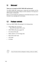
The ASUS P4BGL-MX motherboard is damaged or missing, contact your ASUS P4BGL-MX package for the following items. ASUS P4BGL-MX motherboard Micro-ATX form factor: 8.6 in x 9.6 in ASUS P4BGL-MX series support CD 40-conductor IDE cable Ribbon cable for buying the ASUS® P4BGL-MX motherboard! Before you for a 3.5-inch floppy drive Bag of extra jumper caps User Guide I/O Shield If any of ASUS quality motherboards! 1.1 Welcome! Thank...
The ASUS P4BGL-MX motherboard is damaged or missing, contact your ASUS P4BGL-MX package for the following items. ASUS P4BGL-MX motherboard Micro-ATX form factor: 8.6 in x 9.6 in ASUS P4BGL-MX series support CD 40-conductor IDE cable Ribbon cable for buying the ASUS® P4BGL-MX motherboard! Before you for a 3.5-inch floppy drive Bag of extra jumper caps User Guide I/O Shield If any of ASUS quality motherboards! 1.1 Welcome! Thank...
P4BGL-MX/533 User Manual
Page 13
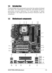
1.3 Introduction The ASUS P4BGL-MX motherboard is loaded with value-added features for guaranteed consumer satisfaction. For future upgrades or system reconfiguration, this chapter provides technical information about the motherboard. 1.4 Motherboard components 1 23 4 56 7 8 14 13 12 15 16 25 24 23 22 ASUS P4BGL-MX Motherboard 9 10 11 17 18 19 20 21 1-3 This motherboard is yet another high-quality motherboard from ASUS.
1.3 Introduction The ASUS P4BGL-MX motherboard is loaded with value-added features for guaranteed consumer satisfaction. For future upgrades or system reconfiguration, this chapter provides technical information about the motherboard. 1.4 Motherboard components 1 23 4 56 7 8 14 13 12 15 16 25 24 23 22 ASUS P4BGL-MX Motherboard 9 10 11 17 18 19 20 21 1-3 This motherboard is yet another high-quality motherboard from ASUS.
P4BGL-MX/533 User Manual
Page 14
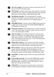
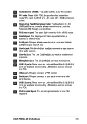
...non-ECC PC2100/1600 DDR SDRAM DIMMs with 400 MHz system bus that include hardware and system voltage monitoring among others. 1-4 Chapter 1: Motherboard Information This Intel ICH4 FW82801DB controller integrates the AC'97 Interface, six Universal Serial Bus 2.0, two IDE Master/Slave controllers, the ITE...66, PIO Modes 3 & 4 IDE devices. This Intel Brookdale GL controller integrates a high performance host interface for two PCI Slots. 11 ASUS ASIC. These two 184-pin DIMM sockets support up to prevent incorrect insertion of the floppy disk cable. 8 IDE Connectors. This power ...
...non-ECC PC2100/1600 DDR SDRAM DIMMs with 400 MHz system bus that include hardware and system voltage monitoring among others. 1-4 Chapter 1: Motherboard Information This Intel ICH4 FW82801DB controller integrates the AC'97 Interface, six Universal Serial Bus 2.0, two IDE Master/Slave controllers, the ITE...66, PIO Modes 3 & 4 IDE devices. This Intel Brookdale GL controller integrates a high performance host interface for two PCI Slots. 11 ASUS ASIC. These two 184-pin DIMM sockets support up to prevent incorrect insertion of the floppy disk cable. 8 IDE Connectors. This power ...
P4BGL-MX/533 User Manual
Page 15
... Network (LAN) through a network hub. 18 Line In jack. This Line In (light blue) jack connects a tape player or other devices. 17 RJ-45 port. ASUS P4BGL-MX Motherboard 1-5 This port allows connection to your serial mouse and other serial devices. 24 USB 2.0 ports. This purple 6-pin connector is for connecting USB devices such...
... Network (LAN) through a network hub. 18 Line In jack. This Line In (light blue) jack connects a tape player or other devices. 17 RJ-45 port. ASUS P4BGL-MX Motherboard 1-5 This port allows connection to your serial mouse and other serial devices. 24 USB 2.0 ports. This purple 6-pin connector is for connecting USB devices such...
P4BGL-MX/533 User Manual
Page 16
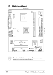
24.4cm (9.6in) 1.5 Motherboard layout 21.9cm (8.6in) PS/2KBMS T: Mouse B: Keyboard Bottom: USB20-3 USB20-4 COM1 Socket 478 CPUFAN1 Super I/O IR1 ATX Power Connector FLOPPY1 DDR DIMM1 (64/72 ... Hub (GMCH) 01 23 SEC_IDE PRI_ IDE RTL8101L ASPDIF1 PCI1 P4BGL-MX PCI2 Intel I/O Controller Hub (ICH4) ASUS Mozart Audio PCI3 Codec CD1 AUX1 CHASFAN1 COM2 USB20_5 USB20_6 BAT1 USBPWR_56 BUZZ1 CHASSIS1 J1 GAME1 ASUS PANEL1 The audio and LAN features are grayed out in the above motherboard layout. 1-6 Chapter 1: Motherboard Information These components are optional.
24.4cm (9.6in) 1.5 Motherboard layout 21.9cm (8.6in) PS/2KBMS T: Mouse B: Keyboard Bottom: USB20-3 USB20-4 COM1 Socket 478 CPUFAN1 Super I/O IR1 ATX Power Connector FLOPPY1 DDR DIMM1 (64/72 ... Hub (GMCH) 01 23 SEC_IDE PRI_ IDE RTL8101L ASPDIF1 PCI1 P4BGL-MX PCI2 Intel I/O Controller Hub (ICH4) ASUS Mozart Audio PCI3 Codec CD1 AUX1 CHASFAN1 COM2 USB20_5 USB20_6 BAT1 USBPWR_56 BUZZ1 CHASSIS1 J1 GAME1 ASUS PANEL1 The audio and LAN features are grayed out in the above motherboard layout. 1-6 Chapter 1: Motherboard Information These components are optional.
P4BGL-MX/533 User Manual
Page 17
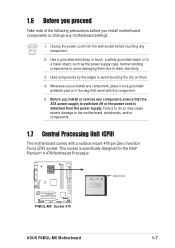
...to a metal object, such as the power supply case, before handling components to avoid damaging them . 4. Whenever you uninstall any motherboard settings. 1. P4BGL-MX P4BGL-MX Socket 478 Gold Arrow ASUS P4BGL-MX Motherboard 1-7 Hold components by the edges to avoid touching the ICs on a grounded antistatic pad or in the bag that the ATX power... is detached from the wall socket before touching any component. 2. 1.6 Before you proceed Take note of the following precautions before you install motherboard components or change any component, place it on them due to static electricity. 3.
...to a metal object, such as the power supply case, before handling components to avoid damaging them . 4. Whenever you uninstall any motherboard settings. 1. P4BGL-MX P4BGL-MX Socket 478 Gold Arrow ASUS P4BGL-MX Motherboard 1-7 Hold components by the edges to avoid touching the ICs on a grounded antistatic pad or in the bag that the ATX power... is detached from the wall socket before touching any component. 2. 1.6 Before you proceed Take note of the following precautions before you install motherboard components or change any component, place it on them due to static electricity. 3.
P4BGL-MX/533 User Manual
Page 18
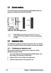
... the expansion cards that it fits in only one direction. See Chapter 2 for the expansion card. 1-8 Chapter 1: Motherboard Information Refer to avoid damaging the DIMM. 1.9 Expansion slots The P4BGL-MX motherboard has three (3) expansion slots. Turn on BIOS setup. 2. DO NOT force a DIMM into a socket to the ... non-ECC PC2100/1600 DDR. 80 Pins P4BGL-MX 104 Pins P4BGL-MX 184-Pin DDR DIMM Sockets 1. Install the software drivers for information on the system and change the necessary BIOS settings, if any. 1.8 System memory The motherboard has two Double Data Rate (DDR) DIMM...
... the expansion cards that it fits in only one direction. See Chapter 2 for the expansion card. 1-8 Chapter 1: Motherboard Information Refer to avoid damaging the DIMM. 1.9 Expansion slots The P4BGL-MX motherboard has three (3) expansion slots. Turn on BIOS setup. 2. DO NOT force a DIMM into a socket to the ... non-ECC PC2100/1600 DDR. 80 Pins P4BGL-MX 104 Pins P4BGL-MX 184-Pin DDR DIMM Sockets 1. Install the software drivers for information on the system and change the necessary BIOS settings, if any. 1.8 System memory The motherboard has two Double Data Rate (DDR) DIMM...
P4BGL-MX/533 User Manual
Page 19
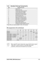
...Onboard USB 1.1 controller 3 - - used - - Onboard Audio - shared - - - - - - Onboard USB 2.0 controller shared Onboard LAN - ASUS P4BGL-MX Motherboard 1-9 IRQ assignments for ISA or PCI devices. 1.9.2 Standard Interrupt Assignments IRQ Standard Function 0 System Timer 1 Keyboard Controller 2 Programmable Interrupt Controller 3 Communications ...IDE controller (dual fifo) 15 Secondary Ultra ATA Controller (dual fifo) *These IRQs are usually available for this motherboard A B C D E F G H PCI slot 1 - - - - - Onboard VGA shared When ...
...Onboard USB 1.1 controller 3 - - used - - Onboard Audio - shared - - - - - - Onboard USB 2.0 controller shared Onboard LAN - ASUS P4BGL-MX Motherboard 1-9 IRQ assignments for ISA or PCI devices. 1.9.2 Standard Interrupt Assignments IRQ Standard Function 0 System Timer 1 Keyboard Controller 2 Programmable Interrupt Controller 3 Communications ...IDE controller (dual fifo) 15 Secondary Ultra ATA Controller (dual fifo) *These IRQs are usually available for this motherboard A B C D E F G H PCI slot 1 - - - - - Onboard VGA shared When ...
P4BGL-MX/533 User Manual
Page 20
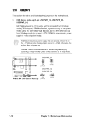
...wake-up (3-pin USBPWR_12, USBPWR_34, USBPWR_56) Set these jumpers are set to +5VSB. P4BGL-MX USBPWR_34 3 2 2 1 +5V (Default) +5VSB USBPWR_12 USBPWR_56 12 23 +5V P4BGL-MX USB Device Wake Up (Default) +5VSB 1-10 Chapter 1: Motherboard Information Set to +5VSB to wake up from S1 sleep mode (CPU stopped, DRAM ... whether under normal condition or in reduced power mode). This feature requires a power supply that can provide at least 1A on the motherboard. 1. 1.10 Jumpers This section describes and illustrates the jumpers on the +5VSB lead when these jumpers to +5V to wake up ...
...wake-up (3-pin USBPWR_12, USBPWR_34, USBPWR_56) Set these jumpers are set to +5VSB. P4BGL-MX USBPWR_34 3 2 2 1 +5V (Default) +5VSB USBPWR_12 USBPWR_56 12 23 +5V P4BGL-MX USB Device Wake Up (Default) +5VSB 1-10 Chapter 1: Motherboard Information Set to +5VSB to wake up from S1 sleep mode (CPU stopped, DRAM ... whether under normal condition or in reduced power mode). This feature requires a power supply that can provide at least 1A on the motherboard. 1. 1.10 Jumpers This section describes and illustrates the jumpers on the +5VSB lead when these jumpers to +5V to wake up ...
P4BGL-MX/533 User Manual
Page 21
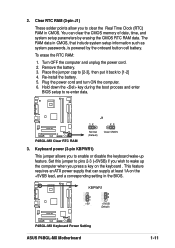
... RAM data in CMOS, that can clear the CMOS memory of date, time, and system setup parameters by the onboard button cell battery. P4BGL-MX P4BGL-MX Clear RTC RAM J1 12 23 Normal (Default) Clear CMOS 3. Place the jumper cap to [2-3], then put it back to re-enter ...data. You can supply at least 1A on the keyboard . Plug the power cord and turn ON the computer. 6. P4BGL-MX KBPWR1 2 1 +5V (Default) 3 2 +5VSB (Default) P4BGL-MX Keyboard Power Setting ASUS P4BGL-MX Motherboard 1-11 To erase the RTC RAM: 1. 2. Set this jumper to pins 2-3 (+5VSB) if you wish to enable...
... RAM data in CMOS, that can clear the CMOS memory of date, time, and system setup parameters by the onboard button cell battery. P4BGL-MX P4BGL-MX Clear RTC RAM J1 12 23 Normal (Default) Clear CMOS 3. Place the jumper cap to [2-3], then put it back to re-enter ...data. You can supply at least 1A on the keyboard . Plug the power cord and turn ON the computer. 6. P4BGL-MX KBPWR1 2 1 +5V (Default) 3 2 +5VSB (Default) P4BGL-MX Keyboard Power Setting ASUS P4BGL-MX Motherboard 1-11 To erase the RTC RAM: 1. 2. Set this jumper to pins 2-3 (+5VSB) if you wish to enable...
P4BGL-MX/533 User Manual
Page 22
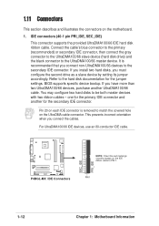
... cables. If you connect non-UltraDMA100/66 devices to PIN 1. one for the primary IDE connector and another UltraDMA100/66 cable. PIN 1 1-12 Chapter 1: Motherboard Information P4BGL-MX P4BGL-MX IDE Connectors SEC_IDE PRI_IDE NOTE: Orient the red markings (usually zigzag) on the UltraDMA cable connector. 1.11 Connectors This section describes and illustrates the connectors...
... cables. If you connect non-UltraDMA100/66 devices to PIN 1. one for the primary IDE connector and another UltraDMA100/66 cable. PIN 1 1-12 Chapter 1: Motherboard Information P4BGL-MX P4BGL-MX IDE Connectors SEC_IDE PRI_IDE NOTE: Orient the red markings (usually zigzag) on the UltraDMA cable connector. 1.11 Connectors This section describes and illustrates the connectors...

P4BGL-MX/533 User Manual
Page 23
P4BGL-MX PIN 1 P4BGL-MX Floppy Disk Drive Connector 3. By default, the pins labeled "Chassis Signal" and "GND" are shorted with intrusion detection feature. After connecting one end to the motherboard, connect the other end to the floppy drive. (Pin 5 is for a chassis designed with a jumper ... use the chassis intrusion detection feature, remove the jumper caps from the pins. CHASSIS1 +5VSB_MB Chassis Signal GND P4BGL-MX P4BGL-MX Chassis Alarm Lead ASUS P4BGL-MX Motherboard 1-13 If you remove any chassis component, the sensor triggers and sends a high-level signal to this lead...
P4BGL-MX PIN 1 P4BGL-MX Floppy Disk Drive Connector 3. By default, the pins labeled "Chassis Signal" and "GND" are shorted with intrusion detection feature. After connecting one end to the motherboard, connect the other end to the floppy drive. (Pin 5 is for a chassis designed with a jumper ... use the chassis intrusion detection feature, remove the jumper caps from the pins. CHASSIS1 +5VSB_MB Chassis Signal GND P4BGL-MX P4BGL-MX Chassis Alarm Lead ASUS P4BGL-MX Motherboard 1-13 If you remove any chassis component, the sensor triggers and sends a high-level signal to this lead...
P4BGL-MX/533 User Manual
Page 24
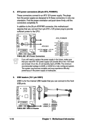
... least 1A on the +5-volt standby lead (+5VSB). ATX_POWER1 Pin 1 +12.0VDC +5VSB ATX12V1 PWR_OK COM P4BGL-MX +12V DC GND +12V DC GND +5.0VDC COM +5.0VDC COM +3.3VDC P4BGL-MX ATX Power Connectors +3.3VDC +5.0VDC +5.0VDC -5.0VDC COM COM COM PS_ON# COM -12.0VDC +3.3VDC If you... plug to provide sufficient power to the front USB ports. USB+5V LDM5 LDP5 GND NC P4BGL-MX P4BGL-MX USB 2.0 Header USB20_5 USB20_6 1 USB+5V LDM6 LDP6 GND 1-14 Chapter 1: Motherboard Information Find the proper orientation and push down firmly until the connectors completely fit. The system may...
... least 1A on the +5-volt standby lead (+5VSB). ATX_POWER1 Pin 1 +12.0VDC +5VSB ATX12V1 PWR_OK COM P4BGL-MX +12V DC GND +12V DC GND +5.0VDC COM +5.0VDC COM +3.3VDC P4BGL-MX ATX Power Connectors +3.3VDC +5.0VDC +5.0VDC -5.0VDC COM COM COM PS_ON# COM -12.0VDC +3.3VDC If you... plug to provide sufficient power to the front USB ports. USB+5V LDM5 LDP5 GND NC P4BGL-MX P4BGL-MX USB 2.0 Header USB20_5 USB20_6 1 USB+5V LDM6 LDP6 GND 1-14 Chapter 1: Motherboard Information Find the proper orientation and push down firmly until the connectors completely fit. The system may...
P4BGL-MX/533 User Manual
Page 25
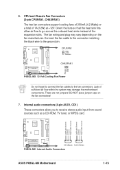
.... CPUFAN1 GND +12V Rotation P4BGL-MX CHASFAN1 Rotation +12V GND P4BGL-MX 12-Volt Cooling Fan Power Do not forget to connect the fan cables to the ground pin. Lack of 1A (12W) at +12V. The fan wiring and plug may damage the motherboard components. Left Audio Channel Ground... Ground Right Audio Channel Left Audio Channel Ground Ground Right Audio Channel P4BGL-MX CD1(Black) AUX1(White) P4BGL-MX Internal Audio Connectors ASUS P4BGL-MX Motherboard 1-15 6. Orient the fans so that the heat sink fins allow you to go across the onboard heat sinks instead...
.... CPUFAN1 GND +12V Rotation P4BGL-MX CHASFAN1 Rotation +12V GND P4BGL-MX 12-Volt Cooling Fan Power Do not forget to connect the fan cables to the ground pin. Lack of 1A (12W) at +12V. The fan wiring and plug may damage the motherboard components. Left Audio Channel Ground... Ground Right Audio Channel Left Audio Channel Ground Ground Right Audio Channel P4BGL-MX CD1(Black) AUX1(White) P4BGL-MX Internal Audio Connectors ASUS P4BGL-MX Motherboard 1-15 6. Orient the fans so that the heat sink fins allow you to go across the onboard heat sinks instead...
P4BGL-MX/533 User Manual
Page 26
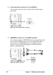
... playing games, and MIDI devices for playing or editing audio files. +5V J1B2 J1CY GND GND J1CX J1B1 +5V P4BGL-MX P4BGL-MX Game Connector GAME1 MIDI_IN J2B2 J2CY MIDI_OUT J2CX J2B1 +5V 1-16 Chapter 1: Motherboard Information Front panel audio connectors (10-1 pin IAPANEL1) This connector connects to this connector. If your package came with...
... playing games, and MIDI devices for playing or editing audio files. +5V J1B2 J1CY GND GND J1CX J1B1 +5V P4BGL-MX P4BGL-MX Game Connector GAME1 MIDI_IN J2B2 J2CY MIDI_OUT J2CX J2B1 +5V 1-16 Chapter 1: Motherboard Information Front panel audio connectors (10-1 pin IAPANEL1) This connector connects to this connector. If your package came with...


