
P4B-FX User Manual
Page 8
... contents of the support CD that comes with the motherboard package. • Glossary This part lists the technical terms that you need when installing the ASUS P4B-FX motherboard. How this guide This user guide contains the information you have to change system settings through the BIOS Setup menus. About this guide is...
... contents of the support CD that comes with the motherboard package. • Glossary This part lists the technical terms that you need when installing the ASUS P4B-FX motherboard. How this guide This user guide contains the information you have to change system settings through the BIOS Setup menus. About this guide is...

P4B-FX User Manual
Page 12
ASUS P4B-FX motherboard
ASUS P4B-FX motherboard

P4B-FX User Manual
Page 13
...ATA100 protocol, and AC '97-compliant audio features, the P4B-FX is damaged or missing, contact your perfect vehicle to set a new benchmark for an effective desktop platform solution. The ASUS P4B-FX motherboard delivers a host of new features and latest technology ... in your P4B-FX package for the following items. ASUS P4B-FX motherboard (Flex-ATX form factor: 9.0 x 7.5 inches) ASUS P4B-FX support CD ASUS 2-port USB module 80-conductor ribbon cable for UltraDMA/33/66/100 IDE drives Ribbon cable for buying the ASUS® P4B-FX motherboard! 1.1 Welcome! ASUS P4B-FX motherboard user guide...
...ATA100 protocol, and AC '97-compliant audio features, the P4B-FX is damaged or missing, contact your perfect vehicle to set a new benchmark for an effective desktop platform solution. The ASUS P4B-FX motherboard delivers a host of new features and latest technology ... in your P4B-FX package for the following items. ASUS P4B-FX motherboard (Flex-ATX form factor: 9.0 x 7.5 inches) ASUS P4B-FX support CD ASUS 2-port USB module 80-conductor ribbon cable for UltraDMA/33/66/100 IDE drives Ribbon cable for buying the ASUS® P4B-FX motherboard! 1.1 Welcome! ASUS P4B-FX motherboard user guide...

P4B-FX User Manual
Page 15
...interface, Ultra ATA/100, Low Pin Count (LPC) interface, Universal Serial Bus (USB) 1.1 interface, PCI interface, and CNR interface. 9 ASUS ASIC. This socket accommodates the Intel® Pentium® 4 478/Northwood Processor with the south bridge Intel I /O subsystem that include hardware... of the Intel 845 (Brookdale) chipset. This chip performs multiple system functions that allows access to prevent incorrect insertion of the system. ASUS P4B-FX motherboard user guide 1-3 The ICH2 integrates I/O functions such as the Intel I/O Controller Hub 2 (ICH2) of the Intel 845 chipset,...
...interface, Ultra ATA/100, Low Pin Count (LPC) interface, Universal Serial Bus (USB) 1.1 interface, PCI interface, and CNR interface. 9 ASUS ASIC. This socket accommodates the Intel® Pentium® 4 478/Northwood Processor with the south bridge Intel I /O subsystem that include hardware... of the Intel 845 (Brookdale) chipset. This chip performs multiple system functions that allows access to prevent incorrect insertion of the system. ASUS P4B-FX motherboard user guide 1-3 The ICH2 integrates I/O functions such as the Intel I/O Controller Hub 2 (ICH2) of the Intel 845 chipset,...

P4B-FX User Manual
Page 17
... connector is for connecting USB devices such as a mouse and PDA. 24 RJ-45 port. Retention Module Base Figure 1-2 Pre-installed Heatsink Retention Module Base ASUS P4B-FX motherboard user guide 1-5 This port allows connection to remove the retention module base when installing the CPU or installing other devices. 23 USB ports. You...
... connector is for connecting USB devices such as a mouse and PDA. 24 RJ-45 port. Retention Module Base Figure 1-2 Pre-installed Heatsink Retention Module Base ASUS P4B-FX motherboard user guide 1-5 This port allows connection to remove the retention module base when installing the CPU or installing other devices. 23 USB ports. You...

P4B-FX User Manual
Page 20
ASUS P4B-FX motherboard
ASUS P4B-FX motherboard

P4B-FX User Manual
Page 21
... in the correct orientation. Make sure to the chassis. The P4B-FX uses the Flex-ATX form factor that you install the motherboard, study the configuration of your chassis to the rear part of the chassis Figure 2-1 Motherboard placement and screw holes ASUS P4B-FX motherboard user guide 2-1 Failure to do so may damage the...
... in the correct orientation. Make sure to the chassis. The P4B-FX uses the Flex-ATX form factor that you install the motherboard, study the configuration of your chassis to the rear part of the chassis Figure 2-1 Motherboard placement and screw holes ASUS P4B-FX motherboard user guide 2-1 Failure to do so may damage the...

P4B-FX User Manual
Page 23
... the power cord is detached from the wall socket before handling components to a metal object, such as the power supply case, before touching any component. 2. ASUS P4B-FX motherboard user guide 2-3 2.3 Before you proceed Take note of the following precautions before you install motherboard components or change any component, place it on them...
... the power cord is detached from the wall socket before handling components to a metal object, such as the power supply case, before touching any component. 2. ASUS P4B-FX motherboard user guide 2-3 2.3 Before you proceed Take note of the following precautions before you install motherboard components or change any component, place it on them...

P4B-FX User Manual
Page 25
Unlock the socket by pressing the lever sideways, then lift it up to 90°-100° angle, otherwise the CPU does not fit in completely. Locate the 478-pin ZIF socket on the motherboard. ASUS P4B-FX motherboard user guide 2-5 Socket Lever 90 - 100 Figure 2-5 CPU Socket Lever at 90° -100° Angle Make sure that the socket lever is lifted up to install a CPU. 1. Figure 2-4 Intel 478-pin ZIF Socket 2. 2.4.2 Installing the CPU Follow these steps to a 90°-100° angle.
Unlock the socket by pressing the lever sideways, then lift it up to 90°-100° angle, otherwise the CPU does not fit in completely. Locate the 478-pin ZIF socket on the motherboard. ASUS P4B-FX motherboard user guide 2-5 Socket Lever 90 - 100 Figure 2-5 CPU Socket Lever at 90° -100° Angle Make sure that the socket lever is lifted up to install a CPU. 1. Figure 2-4 Intel 478-pin ZIF Socket 2. 2.4.2 Installing the CPU Follow these steps to a 90°-100° angle.

P4B-FX User Manual
Page 27
... installation instructions for the CPU, heatsink, and the retention mechanism. If the instructions in this section do not match the CPU documentation, follow the latter. ASUS P4B-FX motherboard user guide 2-7 When you use only Intel certified heatsink and fan. 2.4.3 Installing the heatsink and fan The Intel® Pentium® 4 478/Northwood Processor...
... installation instructions for the CPU, heatsink, and the retention mechanism. If the instructions in this section do not match the CPU documentation, follow the latter. ASUS P4B-FX motherboard user guide 2-7 When you use only Intel certified heatsink and fan. 2.4.3 Installing the heatsink and fan The Intel® Pentium® 4 478/Northwood Processor...

P4B-FX User Manual
Page 29
CPU Fan Connector (CPUFAN) Figure 2-11 CPU Fan Connector ASUS P4B-FX motherboard user guide 2-9 Push down the locks on the motherboard labeled CPUFAN. When secure, the retention locks should point to the module base. Figure 2-10 Fan and Retention Mechanism Installed and Locked 2.4.4 Connecting the CPU fan cable When the fan, heatsink, and the retention mechanism are in place, connect the CPU fan cable to the connector on the retention mechanism to secure the heatsink and fan to opposite directions. 3.
CPU Fan Connector (CPUFAN) Figure 2-11 CPU Fan Connector ASUS P4B-FX motherboard user guide 2-9 Push down the locks on the motherboard labeled CPUFAN. When secure, the retention locks should point to the module base. Figure 2-10 Fan and Retention Mechanism Installed and Locked 2.4.4 Connecting the CPU fan cable When the fan, heatsink, and the retention mechanism are in place, connect the CPU fan cable to the connector on the retention mechanism to secure the heatsink and fan to opposite directions. 3.

P4B-FX User Manual
Page 31
... socket such that the notches on the DIMM match the breaks on the socket. 3. Figure 2-13 Installing a DIMM Unlocked Retaining Clip Figure 2-14 Installed DIMM ASUS P4B-FX motherboard user guide Locked Retaining Clip 2-11 Follow these steps to install a DIMM. 1.
... socket such that the notches on the DIMM match the breaks on the socket. 3. Figure 2-13 Installing a DIMM Unlocked Retaining Clip Figure 2-14 Installed DIMM ASUS P4B-FX motherboard user guide Locked Retaining Clip 2-11 Follow these steps to install a DIMM. 1.

P4B-FX User Manual
Page 33
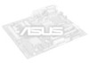
... to use . 4. Align the card connector with the slot and press firmly until the card is already installed in a chassis). 3. Figure 2-16 Installing a PCI Card ASUS P4B-FX motherboard user guide 2-13 The motherboard has three PCI slots and one Accelerated Graphics Port (AGP) slot. The following sub-sections describe the slots and...
... to use . 4. Align the card connector with the slot and press firmly until the card is already installed in a chassis). 3. Figure 2-16 Installing a PCI Card ASUS P4B-FX motherboard user guide 2-13 The motherboard has three PCI slots and one Accelerated Graphics Port (AGP) slot. The following sub-sections describe the slots and...
P4B-FX User Manual
Page 35
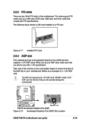
... Card 2.6.4 AGP slot This motherboard has an Accelerated Graphics Port (AGP) slot that you ask for 1.5v P4B-FX Accelerated Graphics Port (AGP) Figure 2-18 Accelerated Graphics Port (AGP) Slot Location ASUS P4B-FX motherboard user guide 2-15 P4B-FX Keyed for one with PCI specifications. The following figure shows a LAN card installed on your motherboard. The...
... Card 2.6.4 AGP slot This motherboard has an Accelerated Graphics Port (AGP) slot that you ask for 1.5v P4B-FX Accelerated Graphics Port (AGP) Figure 2-18 Accelerated Graphics Port (AGP) Slot Location ASUS P4B-FX motherboard user guide 2-15 P4B-FX Keyed for one with PCI specifications. The following figure shows a LAN card installed on your motherboard. The...
P4B-FX User Manual
Page 37
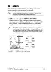
.... Set to pins 2-3 to pins 2-3 (Disabled) by default. These jumpers are set to disable the USB wake-up . USBPWR01 12 Enabled 23 Disabled (Default) USBPWR23 P4B-FX P4B-FX USB Device Wake-Up 12 Enabled 23 Disabled (Default) Figure 2-20 USB Device Wake-up feature requires a power supply that can provide at least 1A... on the motherboard allow you to change some feature settings to suit your customized system configuration. The USB device wake-up Settings ASUS P4B-FX motherboard user guide 2-17 2.7 Jumpers The jumpers on the +5VSB lead.
.... Set to pins 2-3 to pins 2-3 (Disabled) by default. These jumpers are set to disable the USB wake-up . USBPWR01 12 Enabled 23 Disabled (Default) USBPWR23 P4B-FX P4B-FX USB Device Wake-Up 12 Enabled 23 Disabled (Default) Figure 2-20 USB Device Wake-up feature requires a power supply that can provide at least 1A... on the motherboard allow you to change some feature settings to suit your customized system configuration. The USB device wake-up Settings ASUS P4B-FX motherboard user guide 2-17 2.7 Jumpers The jumpers on the +5VSB lead.

P4B-FX User Manual
Page 39
The default setting is powered by erasing the CMOS RTC RAM data. The RAM data in CMOS. P4B-FX P4B-FX Clear RTC RAM Figure 2-24 Clear RTC RAM Intel I/O Controller Hub (ICH2) CLRTC Short solder points to re-enter data. To erase the RTC RAM: 1. ... button cell battery. Short the two pads for a few seconds. 4. Hold down the key during the boot process and enter BIOS setup to Clear CMOS ASUS P4B-FX motherboard user guide 2-19 LAN controller (3-pin LAN_EN) (on LAN models only) This jumper allows you to enable or disable the onboard Local Area Network...
The default setting is powered by erasing the CMOS RTC RAM data. The RAM data in CMOS. P4B-FX P4B-FX Clear RTC RAM Figure 2-24 Clear RTC RAM Intel I/O Controller Hub (ICH2) CLRTC Short solder points to re-enter data. To erase the RTC RAM: 1. ... button cell battery. Short the two pads for a few seconds. 4. Hold down the key during the boot process and enter BIOS setup to Clear CMOS ASUS P4B-FX motherboard user guide 2-19 LAN controller (3-pin LAN_EN) (on LAN models only) This jumper allows you to enable or disable the onboard Local Area Network...

P4B-FX User Manual
Page 41
.... The UltraDMA/66 cable included in the motherboard package also supports UltraDMA/100. one for the primary IDE connector and another UltraDMA/100/66 cable. ASUS P4B-FX motherboard user guide 2-21 The hole near the blue connector on the IDE ribbon cable to be both master devices with two ribbon cables - If...
.... The UltraDMA/66 cable included in the motherboard package also supports UltraDMA/100. one for the primary IDE connector and another UltraDMA/100/66 cable. ASUS P4B-FX motherboard user guide 2-21 The hole near the blue connector on the IDE ribbon cable to be both master devices with two ribbon cables - If...

P4B-FX User Manual
Page 43
... for use with an infrared module, the COM2 port does not work. IR_CN 1 Front View Back View +5V IRRX GND IRTX P4B-FX P4B-FX Infrared Module Connector Figure 2-30 Infrared Module Connector ASUS P4B-FX motherboard user guide IRTX GND IRRX +5V (NC) 2-23 USB header (10-1 pin USB2) If the USB ports on system chassis...
... for use with an infrared module, the COM2 port does not work. IR_CN 1 Front View Back View +5V IRRX GND IRTX P4B-FX P4B-FX Infrared Module Connector Figure 2-30 Infrared Module Connector ASUS P4B-FX motherboard user guide IRTX GND IRRX +5V (NC) 2-23 USB header (10-1 pin USB2) If the USB ports on system chassis...

P4B-FX User Manual
Page 45
... chassis has this audio module, you to the front panel connector. CD1 (Black) AUX (White) Left Audio Channel Ground Right Audio Channel P4B-FX P4B-FX Internal Audio Connectors Figure 2-32 Internal Audio Connectors 9. Internal audio connectors (4-pin CD1, AUX) (on the rear panel. This connector is.../speaker to receive stereo audio input from sound sources such as a CD-ROM, TV tuner, or MPEG card. 8. HPHONE 1 P4B-FX P4B-FX True-Level Line Out Header Figure 2-33 Headphone True-level Line Out Connector Earphone Left GND Earphone Right ASUS P4B-FX motherboard user guide 2-25
... chassis has this audio module, you to the front panel connector. CD1 (Black) AUX (White) Left Audio Channel Ground Right Audio Channel P4B-FX P4B-FX Internal Audio Connectors Figure 2-32 Internal Audio Connectors 9. Internal audio connectors (4-pin CD1, AUX) (on the rear panel. This connector is.../speaker to receive stereo audio input from sound sources such as a CD-ROM, TV tuner, or MPEG card. 8. HPHONE 1 P4B-FX P4B-FX True-Level Line Out Header Figure 2-33 Headphone True-level Line Out Connector Earphone Left GND Earphone Right ASUS P4B-FX motherboard user guide 2-25
P4B-FX User Manual
Page 47
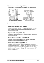
...panel functions. Keyboard Lock Speaker Power LED Connector PLED+ PLEDKeylock Ground +5V Ground Ground Speaker MLED+ MLEDExtSMI# Ground PWR GND Reset Ground P4B-FX P4B-FX System Panel Connectors Message LED SMI Lead Reset SW ATX Power Switch* * Requires an ATX power supply. Figure 2-36 System Panel ... pin connector connects to hear system beeps and warnings. • System Message LED Lead (2-pin MSGLED) This 2-pin connector is received. ASUS P4B-FX motherboard user guide 2-27 The LED blinks when data is for this LED is ON, when there is no incoming data signal. The normal...
...panel functions. Keyboard Lock Speaker Power LED Connector PLED+ PLEDKeylock Ground +5V Ground Ground Speaker MLED+ MLEDExtSMI# Ground PWR GND Reset Ground P4B-FX P4B-FX System Panel Connectors Message LED SMI Lead Reset SW ATX Power Switch* * Requires an ATX power supply. Figure 2-36 System Panel ... pin connector connects to hear system beeps and warnings. • System Message LED Lead (2-pin MSGLED) This 2-pin connector is received. ASUS P4B-FX motherboard user guide 2-27 The LED blinks when data is for this LED is ON, when there is no incoming data signal. The normal...


