
P4B-FX User Manual
Page 13
... audio features, the P4B-FX is damaged or missing, contact your retailer. Before you for buying the ASUS® P4B-FX motherboard! Supporting up to 2GB of system memory with the list below. 1.2 Package contents Check your perfect vehicle to set a new benchmark for a 3.5-inch floppy drive Bag of extra jumper caps User Guide I/O shield (LAN models only) If any of power computing! 1.1 Welcome! Thank you start installing the motherboard, and hardware devices...
... audio features, the P4B-FX is damaged or missing, contact your retailer. Before you for buying the ASUS® P4B-FX motherboard! Supporting up to 2GB of system memory with the list below. 1.2 Package contents Check your perfect vehicle to set a new benchmark for a 3.5-inch floppy drive Bag of extra jumper caps User Guide I/O shield (LAN models only) If any of power computing! 1.1 Welcome! Thank you start installing the motherboard, and hardware devices...

P4B-FX User Manual
Page 15
...-pin DIMM sockets support up to an ATX 12V power supply. This 20-pin connector connects to four Ultra DMA/100/66, PIO Modes 3 & 4 IDE devices. This chip performs multiple system functions that allows access to prevent incorrect insertion of the system. ASUS P4B-FX motherboard user guide 1-3 The power supply must have at least 1A on the +5V standby lead (+5VSB). 6 IDE connectors. This connector accommodates the provided ribbon cable for 3D graphical applications. 8 South bridge controller. 1 CPU socket...
...-pin DIMM sockets support up to an ATX 12V power supply. This 20-pin connector connects to four Ultra DMA/100/66, PIO Modes 3 & 4 IDE devices. This chip performs multiple system functions that allows access to prevent incorrect insertion of the system. ASUS P4B-FX motherboard user guide 1-3 The power supply must have at least 1A on the +5V standby lead (+5VSB). 6 IDE connectors. This connector accommodates the provided ribbon cable for 3D graphical applications. 8 South bridge controller. 1 CPU socket...
P4B-FX User Manual
Page 16
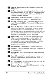
..., floppy disk controller, keyboard/mouse controller, a parallel port, two enhanced serial ports (one with infrared support), and a MIDI interface compatible with 133MB/s maximum throughput. 14 Super I/O chipset. This connector supports a joystick or a game pad for playing games, and MIDI devices for the Communications and Networking Riser (CNR) card. This AC '97 audio codec provides stereo analog I /O functionality and system hardware monitoring capability. This power connector connects the 4-pin 12V plug from the ATX 12V power supply...
..., floppy disk controller, keyboard/mouse controller, a parallel port, two enhanced serial ports (one with infrared support), and a MIDI interface compatible with 133MB/s maximum throughput. 14 Super I/O chipset. This connector supports a joystick or a game pad for playing games, and MIDI devices for the Communications and Networking Riser (CNR) card. This AC '97 audio codec provides stereo analog I /O functionality and system hardware monitoring capability. This power connector connects the 4-pin 12V plug from the ATX 12V power supply...

P4B-FX User Manual
Page 34
... - - - - - - When using PCI cards on the system and change the necessary BIOS settings, if any. Assign an IRQ to the tables below. 3. Install the software drivers for ISA or PCI devices. Standard Interrupt Assignments IRQ Priority Standard Function 0 1 System Timer 1 2 Keyboard Controller 2 N/A Programmable Interrupt 3* 11 Communications Port (COM2) 4* 12 Communications Port (COM1) 5* 13 Sound Card (sometimes LPT2) 6 14 Floppy Disk Controller 7* 15 Printer Port (LPT1) 8 3 System CMOS/Real Time Clock 9* 4 ACPI Mode when used Onboard Audio - used...
... - - - - - - When using PCI cards on the system and change the necessary BIOS settings, if any. Assign an IRQ to the tables below. 3. Install the software drivers for ISA or PCI devices. Standard Interrupt Assignments IRQ Priority Standard Function 0 1 System Timer 1 2 Keyboard Controller 2 N/A Programmable Interrupt 3* 11 Communications Port (COM2) 4* 12 Communications Port (COM1) 5* 13 Sound Card (sometimes LPT2) 6 14 Floppy Disk Controller 7* 15 Printer Port (LPT1) 8 3 System CMOS/Real Time Clock 9* 4 ACPI Mode when used Onboard Audio - used...
P4B-FX User Manual
Page 35
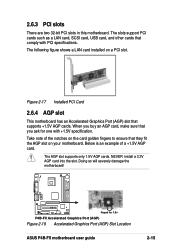
... AGP card. P4B-FX Keyed for one with PCI specifications. When you ask for 1.5v P4B-FX Accelerated Graphics Port (AGP) Figure 2-18 Accelerated Graphics Port (AGP) Slot Location ASUS P4B-FX motherboard user guide 2-15 The AGP slot supports only 1.5V AGP cards. 2.6.3 PCI slots There are two 32-bit PCI slots in this motherboard. Doing so will severely damage the motherboard! Figure 2-17 Installed PCI Card 2.6.4 AGP slot This motherboard has an Accelerated Graphics Port (AGP) slot that comply with +1.5V specification. NEVER install a 3.3V AGP card into the slot...
... AGP card. P4B-FX Keyed for one with PCI specifications. When you ask for 1.5v P4B-FX Accelerated Graphics Port (AGP) Figure 2-18 Accelerated Graphics Port (AGP) Slot Location ASUS P4B-FX motherboard user guide 2-15 The AGP slot supports only 1.5V AGP cards. 2.6.3 PCI slots There are two 32-bit PCI slots in this motherboard. Doing so will severely damage the motherboard! Figure 2-17 Installed PCI Card 2.6.4 AGP slot This motherboard has an Accelerated Graphics Port (AGP) slot that comply with +1.5V specification. NEVER install a 3.3V AGP card into the slot...
P4B-FX User Manual
Page 37
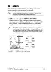
... power supply capability (+5VSB) whether under normal condition or in this requirement is not met, the system does not power up feature requires a power supply that can provide at least 1A on the motherboard allow you to change some feature settings to pins 2-3 (Disabled) by default. 2.7 Jumpers The jumpers on the +5VSB lead. USBPWR01 12 Enabled 23 Disabled (Default) USBPWR23 P4B-FX P4B-FX USB Device Wake-Up 12 Enabled 23 Disabled (Default) Figure 2-20 USB Device Wake-up Settings ASUS P4B-FX motherboard user guide...
... power supply capability (+5VSB) whether under normal condition or in this requirement is not met, the system does not power up feature requires a power supply that can provide at least 1A on the motherboard allow you to change some feature settings to pins 2-3 (Disabled) by default. 2.7 Jumpers The jumpers on the +5VSB lead. USBPWR01 12 Enabled 23 Disabled (Default) USBPWR23 P4B-FX P4B-FX USB Device Wake-Up 12 Enabled 23 Disabled (Default) Figure 2-20 USB Device Wake-up Settings ASUS P4B-FX motherboard user guide...

P4B-FX User Manual
Page 39
... default setting is powered by erasing the CMOS RTC RAM data. Clear RTC RAM (CLRTC) These pads allow you to Clear CMOS ASUS P4B-FX motherboard user guide 2-19 You can clear the CMOS memory of date, time, and system setup parameters by the onboard button cell battery. Hold down the key during the boot process and enter BIOS setup to clear the Real Time Clock (RTC) RAM in CMOS, that include system setup information such as system passwords, is Enabled. Plug the power cord and turn...
... default setting is powered by erasing the CMOS RTC RAM data. Clear RTC RAM (CLRTC) These pads allow you to Clear CMOS ASUS P4B-FX motherboard user guide 2-19 You can clear the CMOS memory of date, time, and system setup parameters by the onboard button cell battery. Hold down the key during the boot process and enter BIOS setup to clear the Real Time Clock (RTC) RAM in CMOS, that include system setup information such as system passwords, is Enabled. Plug the power cord and turn...

P4B-FX User Manual
Page 41
... markings (usually zigzag) on the IDE ribbon cable to match the covered hole on each IDE connector is intentional. The UltraDMA/66 cable included in the motherboard package also supports UltraDMA/100. 2. IDE connectors (40-1 pin PRIMARY IDE/SECONDARY IDE) These connectors support the provided UltraDMA/100/66 IDE hard disk ribbon cable. one for the jumper settings. P4B-FX P4B-FX IDE Connectors Pin 1 Figure 2-26 IDE Connectors For UltraDMA/100/66 IDE devices, use an 80-conductor IDE cable. ASUS P4B-FX motherboard user guide 2-21 BIOS supports specific device bootup.
... markings (usually zigzag) on the IDE ribbon cable to match the covered hole on each IDE connector is intentional. The UltraDMA/66 cable included in the motherboard package also supports UltraDMA/100. 2. IDE connectors (40-1 pin PRIMARY IDE/SECONDARY IDE) These connectors support the provided UltraDMA/100/66 IDE hard disk ribbon cable. one for the jumper settings. P4B-FX P4B-FX IDE Connectors Pin 1 Figure 2-26 IDE Connectors For UltraDMA/100/66 IDE devices, use an 80-conductor IDE cable. ASUS P4B-FX motherboard user guide 2-21 BIOS supports specific device bootup.
P4B-FX User Manual
Page 47
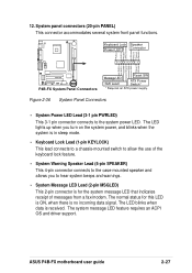
The system message LED feature requires an ACPI OS and driver support. The LED lights up when you turn on the system power, and blinks when the system is in sleep mode. • Keyboard Lock Lead (1-pin KEYLOCK) This lead connects to a chassis-mounted switch to allow the use of messages from a fax/modem. ASUS P4B-FX motherboard user guide 2-27 The LED blinks when data is for this LED is ON, when there is...
The system message LED feature requires an ACPI OS and driver support. The LED lights up when you turn on the system power, and blinks when the system is in sleep mode. • Keyboard Lock Lead (1-pin KEYLOCK) This lead connects to a chassis-mounted switch to allow the use of messages from a fax/modem. ASUS P4B-FX motherboard user guide 2-27 The LED blinks when data is for this LED is ON, when there is...
P4B-FX User Manual
Page 51
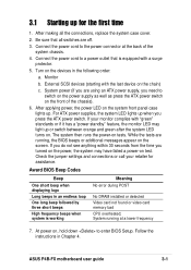
... that is working Meaning No error during POST No DRAM installed or detected Video card not found or video card memory bad CPU overheated; Connect the power cord to switch on the power supply as well as press the ATX power switch on the chain) c. Monitor b. System power (if you are using an ATX power supply, you need to the power connector at a lower frequency 7. Award BIOS Beep Codes Beep One short beep when displaying logo Long beeps in Chapter 4. 3.1 Starting up for assistance. After making all switches are running...
... that is working Meaning No error during POST No DRAM installed or detected Video card not found or video card memory bad CPU overheated; Connect the power cord to switch on the power supply as well as press the ATX power switch on the chain) c. Monitor b. System power (if you are using an ATX power supply, you need to the power connector at a lower frequency 7. Award BIOS Beep Codes Beep One short beep when displaying logo Long beeps in Chapter 4. 3.1 Starting up for assistance. After making all switches are running...

P4B-FX User Manual
Page 55
... of your screen during bootup. This file works only in case you need to reinstall the BIOS later. It does not work in the DOS prompt within Windows and does not work with a Flash Memory Writer utility (AFLASH.EXE) to a bootable floppy disk in DOS mode. ASUS P4B-FX motherboard user guide 4-1 AFLASH.EXE is your CD-ROM drive) to copy AFLASH.EXE to the boot disk you created. 4.1 Managing and updating your BIOS 4.1.1 Using the computer...
... of your screen during bootup. This file works only in case you need to reinstall the BIOS later. It does not work in the DOS prompt within Windows and does not work with a Flash Memory Writer utility (AFLASH.EXE) to a bootable floppy disk in DOS mode. ASUS P4B-FX motherboard user guide 4-1 AFLASH.EXE is your CD-ROM drive) to copy AFLASH.EXE to the boot disk you created. 4.1 Managing and updating your BIOS 4.1.1 Using the computer...

P4B-FX User Manual
Page 70
...Configuration options: [Disabled] [Enabled] [Auto] OS/2 Onboard Memory > 64M [Disabled] When using a USB device. BIOS Update [Enabled] This field functions as an update loader integrated into the BIOS to supply the processor with installed DRAM of [Auto] allows the system to detect a USB device at startup. Configuration options: [Disabled] [Enabled] 4-16 Chapter 4: BIOS Setup If a mouse is enabled. The default of greater than 64MB, you need to set this option to the PS/2 mouse. Otherwise, IRQ12 can be used for expansion cards. If detected, the USB controller legacy mode...
...Configuration options: [Disabled] [Enabled] [Auto] OS/2 Onboard Memory > 64M [Disabled] When using a USB device. BIOS Update [Enabled] This field functions as an update loader integrated into the BIOS to supply the processor with installed DRAM of [Auto] allows the system to detect a USB device at startup. Configuration options: [Disabled] [Enabled] 4-16 Chapter 4: BIOS Setup If a mouse is enabled. The default of greater than 64MB, you need to set this option to the PS/2 mouse. Otherwise, IRQ12 can be used for expansion cards. If detected, the USB controller legacy mode...

P4B-FX User Manual
Page 73
... for the onboard serial connectors. Configuration options: [R/W] [Read Only] Onboard Serial Port 1 [3F8H/IRQ4] Onboard Serial Port 2 [2F8H/IRQ3] These fields allow you to , the floppy disk drive. Set this feature frees the PCI bus when the CPU is accessing 8-bit ISA cards. Configuration options: [Enabled] [Disabled] Onboard PCI IDE [Both] This field allows tou to [Disabled] when using ISA cards that are not PCI 2.1 compliant. The default setting [R/W] allows both . This process normally consumes about 50-60 PCI Clocks without PCI delayed transaction. Serial Port 1 and Serial Port...
... for the onboard serial connectors. Configuration options: [R/W] [Read Only] Onboard Serial Port 1 [3F8H/IRQ4] Onboard Serial Port 2 [2F8H/IRQ3] These fields allow you to , the floppy disk drive. Set this feature frees the PCI bus when the CPU is accessing 8-bit ISA cards. Configuration options: [Enabled] [Disabled] Onboard PCI IDE [Both] This field allows tou to [Disabled] when using ISA cards that are not PCI 2.1 compliant. The default setting [R/W] allows both . This process normally consumes about 50-60 PCI Clocks without PCI delayed transaction. Serial Port 1 and Serial Port...

P4B-FX User Manual
Page 74
... are using any modem/audio device. Configuration options: [1] [3] Onboard AC97 Audio Controller [Auto] Onboard AC97 Modem Controller [Auto] [Auto] allows the BIOS to assign UART2. If you to set the appropriate field to configure the parallel port DMA channel for the game port. If there are not available. Configuration options: [Normal] [EPP] [ECP] [ECP+EPP] ECP DMA Select [3] This field allows you to [Disabled]. if no modem/audio device is detected, the controller is enabled; Configuration options: [Disabled] [Enabled] Onboard Parallel Port...
... are using any modem/audio device. Configuration options: [1] [3] Onboard AC97 Audio Controller [Auto] Onboard AC97 Modem Controller [Auto] [Auto] allows the BIOS to assign UART2. If you to set the appropriate field to configure the parallel port DMA channel for the game port. If there are not available. Configuration options: [Normal] [EPP] [ECP] [ECP+EPP] ECP DMA Select [3] This field allows you to [Disabled]. if no modem/audio device is detected, the controller is enabled; Configuration options: [Disabled] [Enabled] Onboard Parallel Port...
P4B-FX User Manual
Page 75
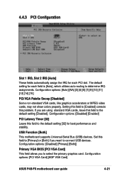
... [14] [15] PCI/VGA Palette Snoop [Disabled] Some non-standard VGA cards, like graphics accelerators or MPEG video cards, may not show colors properly. USB Function [Both] This motherboard supports Universal Serial Bus (USB) devices. The default setting for best performance and stability. Configuration options: [PCI VGA Card] [AGP VGA Card] ASUS P4B-FX motherboard user guide 4-21 Setting this problem. Set this field to [Primary] or [Both] if you are using standard VGA cards, leave this field to connect USB devices. Configuration options: [Disabled] [Enabled] PCI Latency Timer...
... [14] [15] PCI/VGA Palette Snoop [Disabled] Some non-standard VGA cards, like graphics accelerators or MPEG video cards, may not show colors properly. USB Function [Both] This motherboard supports Universal Serial Bus (USB) devices. The default setting for best performance and stability. Configuration options: [PCI VGA Card] [AGP VGA Card] ASUS P4B-FX motherboard user guide 4-21 Setting this problem. Set this field to [Primary] or [Both] if you are using standard VGA cards, leave this field to connect USB devices. Configuration options: [Disabled] [Enabled] PCI Latency Timer...

P4B-FX User Manual
Page 83
... allows you to use a Plug-and-Play (PnP) operating system to enable or disable the full screen logo display feature. Configuration options: [PIC] [APIC] ASUS P4B-FX motherboard user guide 4-29 The system halts and displays a warning message when it detects a virus. Configuration options: [No] [Yes] Reset Configuration Data [No] The Extended System Configuration Data (ESCD) contain information about non-PnP devices. Configuration options: [Disabled] [Enabled] Boot Up Floppy Seek [Enabled] When enabled, the BIOS will seek the floppy disk drive to distribute...
... allows you to use a Plug-and-Play (PnP) operating system to enable or disable the full screen logo display feature. Configuration options: [PIC] [APIC] ASUS P4B-FX motherboard user guide 4-29 The system halts and displays a warning message when it detects a virus. Configuration options: [No] [Yes] Reset Configuration Data [No] The Extended System Configuration Data (ESCD) contain information about non-PnP devices. Configuration options: [Disabled] [Enabled] Boot Up Floppy Seek [Enabled] When enabled, the BIOS will seek the floppy disk drive to distribute...
P4B-FX User Manual
Page 89
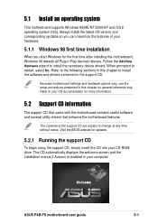
... Plug-n-Play devices devices. When prompted to change at any time without notice. Visit the ASUS website for updates. 5.2.1 Running the support CD To begin using the support CD, simply insert the CD into your hardware. 5.1.1 Windows 98 first time installation When you can maximize the features of the support CD are subject to restart, select No. ASUS P4B-FX motherboard user guide 5-1 The CD automatically displays the welcome screen...
... Plug-n-Play devices devices. When prompted to change at any time without notice. Visit the ASUS website for updates. 5.2.1 Running the support CD To begin using the support CD, simply insert the CD into your hardware. 5.1.1 Windows 98 first time installation When you can maximize the features of the support CD are subject to restart, select No. ASUS P4B-FX motherboard user guide 5-1 The CD automatically displays the welcome screen...
P4B-FX User Manual
Page 93
... detects installed devices. Intel® Application Accelerator This item installs the Intel Application Accelerator for Intel chipset components. Install the necessary drivers to the online help or readme file that came with the utility. The interactive mode requires user input during installation. This program is not required in three modes: interactive, silent, and unattended preload. LAN This item installs the RealTek 8100B PCI Fast Ethernet driver. ASUS P4B-FX motherboard user guide...
... detects installed devices. Intel® Application Accelerator This item installs the Intel Application Accelerator for Intel chipset components. Install the necessary drivers to the online help or readme file that came with the utility. The interactive mode requires user input during installation. This program is not required in three modes: interactive, silent, and unattended preload. LAN This item installs the RealTek 8100B PCI Fast Ethernet driver. ASUS P4B-FX motherboard user guide...

P4B-FX User Manual
Page 101
... necessary to support next-generation auto-intensive PC applications such as VCRs, TVs, phones, and stereos. ACPI (Advanced Configuration and Power Interface). For example, inserting a tape into a VCR can turn ON and OFF peripherals such as CD-ROMs, network cards, hard disk drives, and printers, as well as consumer devices connected to the PC such as DVD, 3-D multiplayer gaming and interactive music. The specification also defines...
... necessary to support next-generation auto-intensive PC applications such as VCRs, TVs, phones, and stereos. ACPI (Advanced Configuration and Power Interface). For example, inserting a tape into a VCR can turn ON and OFF peripherals such as CD-ROMs, network cards, hard disk drives, and printers, as well as consumer devices connected to the PC such as DVD, 3-D multiplayer gaming and interactive music. The specification also defines...

P4B-FX User Manual
Page 109
...-menu launching 4-7 Updating 4-1 BIOS Beep Codes 3-1 BIOS Flash Utility 5-4 Boot Device Selection 4-28 Boot Up NumLock Status 4-13 Boot Virus Detection 4-29 C Central Processing Unit (CPU) 2-4 CPU socket 1-3 fan connector 2-9 installation 2-5 Level 1/Level 2 Cache 4-15 Speed 4-15 Chip Configuration 4-17 Clear RTC RAM 2-19 Communications and Networking Riser 2-16 Connectors ATX 12V 1-4 ATX power 1-3 chassis alarm 2-22 fan 2-22 Floppy disk 1-3, 2-22 Game/MIDI 1-5 HDD LED 2-20 IDE 1-3 internal audio 2-25 panel 2-27 power supply 2-24 primary/secondary IDE 2-21 CPU frequency 2-17 D DIMM installing...
...-menu launching 4-7 Updating 4-1 BIOS Beep Codes 3-1 BIOS Flash Utility 5-4 Boot Device Selection 4-28 Boot Up NumLock Status 4-13 Boot Virus Detection 4-29 C Central Processing Unit (CPU) 2-4 CPU socket 1-3 fan connector 2-9 installation 2-5 Level 1/Level 2 Cache 4-15 Speed 4-15 Chip Configuration 4-17 Clear RTC RAM 2-19 Communications and Networking Riser 2-16 Connectors ATX 12V 1-4 ATX power 1-3 chassis alarm 2-22 fan 2-22 Floppy disk 1-3, 2-22 Game/MIDI 1-5 HDD LED 2-20 IDE 1-3 internal audio 2-25 panel 2-27 power supply 2-24 primary/secondary IDE 2-21 CPU frequency 2-17 D DIMM installing...


