
P4B-FX User Manual
Page 43
...panel are inadequate, a USB header is available for use with IR. If you installed an infrared module, enable the UART2 Use Standard Infrared parameter in BIOS to the pin definitions. IR_CN 1 Front View Back View +5V IRRX GND IRTX P4B-FX P4B-FX Infrared Module Connector Figure 2-30 Infrared Module Connector ASUS P4B-FX... on system chassis that support this feature. If you enable the onboard infrared feature for details. USBP3+ GND P4B-FX USB Header Figure 2-29 USB Header 6. Connect a 2-port USB connector set to the USB header and mount the USB bracket to an open slot in Back...
...panel are inadequate, a USB header is available for use with IR. If you installed an infrared module, enable the UART2 Use Standard Infrared parameter in BIOS to the pin definitions. IR_CN 1 Front View Back View +5V IRRX GND IRTX P4B-FX P4B-FX Infrared Module Connector Figure 2-30 Infrared Module Connector ASUS P4B-FX... on system chassis that support this feature. If you enable the onboard infrared feature for details. USBP3+ GND P4B-FX USB Header Figure 2-29 USB Header 6. Connect a 2-port USB connector set to the USB header and mount the USB bracket to an open slot in Back...

P4B-FX User Manual
Page 45
... this audio module, you to an optional front panel audio module using a 3-pin audio cable. HPHONE 1 P4B-FX P4B-FX True-Level Line Out Header Figure 2-33 Headphone True-level Line Out Connector Earphone Left GND Earphone Right ASUS P4B-FX motherboard user guide 2-25 This connector is disabled when there is a line out device connected to the front...
... this audio module, you to an optional front panel audio module using a 3-pin audio cable. HPHONE 1 P4B-FX P4B-FX True-Level Line Out Header Figure 2-33 Headphone True-level Line Out Connector Earphone Left GND Earphone Right ASUS P4B-FX motherboard user guide 2-25 This connector is disabled when there is a line out device connected to the front...
P4B-FX User Manual
Page 46
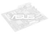
...CHASSIS 1 +5Volt (Power Supply Stand By) Chassis Signal Ground P4B-FX P4B-FX Chassis Alarm Lead Figure 2-35 Chassis Alarm Lead 2-26 Chapter 2: Hardware information If your chassis has this lead to the front panel connector . This requires an external detection mechanism such as a ... wish to use one microphone at a time. Internal microphone connector (3-pin MIC2) (on the rear panel. If you can connect a microphone to record a chassis intrusion event. MIC2 1 P4B-FX P4B-FX Internal Microphone Connector Figure 2-34 Internal Microphone Connector 11. MIC Power MIC Input Ground 10.
...CHASSIS 1 +5Volt (Power Supply Stand By) Chassis Signal Ground P4B-FX P4B-FX Chassis Alarm Lead Figure 2-35 Chassis Alarm Lead 2-26 Chapter 2: Hardware information If your chassis has this lead to the front panel connector . This requires an external detection mechanism such as a ... wish to use one microphone at a time. Internal microphone connector (3-pin MIC2) (on the rear panel. If you can connect a microphone to record a chassis intrusion event. MIC2 1 P4B-FX P4B-FX Internal Microphone Connector Figure 2-34 Internal Microphone Connector 11. MIC Power MIC Input Ground 10.
P4B-FX User Manual
Page 47
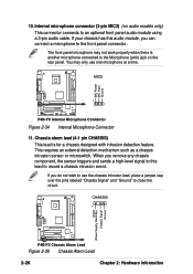
... Ground P4B-FX P4B-FX System Panel Connectors Message LED SMI Lead Reset SW ATX Power Switch* * Requires an ATX power supply. Figure 2-36 System Panel Connectors • System Power LED Lead (3-1 pin PWRLED) This 3-1 pin connector connects to hear system beeps and warnings. • System Message LED Lead (2-pin MSGLED) This 2-pin connector is received. ASUS P4B-FX motherboard...
... Ground P4B-FX P4B-FX System Panel Connectors Message LED SMI Lead Reset SW ATX Power Switch* * Requires an ATX power supply. Figure 2-36 System Panel Connectors • System Power LED Lead (3-1 pin PWRLED) This 3-1 pin connector connects to hear system beeps and warnings. • System Message LED Lead (2-pin MSGLED) This 2-pin connector is received. ASUS P4B-FX motherboard...
P4B-FX User Manual
Page 51
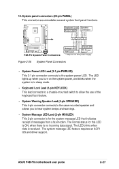
...monitor complies with the last device on , hold down to the power connector at a lower frequency 7. 3.1 Starting up for assistance. ASUS P4B-FX motherboard user guide 3-1 Connect the power cord to enter BIOS Setup. External SCSI devices (starting with "green" standards or if it has a "power standby" feature..., the monitor LED may have failed a power-on the system front panel case lights up. At power on the chain) c. ...
...monitor complies with the last device on , hold down to the power connector at a lower frequency 7. 3.1 Starting up for assistance. ASUS P4B-FX motherboard user guide 3-1 Connect the power cord to enter BIOS Setup. External SCSI devices (starting with "green" standards or if it has a "power standby" feature..., the monitor LED may have failed a power-on the system front panel case lights up. At power on the chain) c. ...
