
P4B-E User Manual
Page 1
Motherboard ® P4B-E User Guide
Motherboard ® P4B-E User Guide

P4B-E User Manual
Page 8
... chapter lists the hardware setup procedures that you need when installing the ASUS P4B-E motherboard. It includes brief descriptions of the special attributes of the topics found in this document. viii It includes description of the switches, jumpers, and connectors on the motherboard. • Chapter 3: Powering up This chapter describes the power up sequence...
... chapter lists the hardware setup procedures that you need when installing the ASUS P4B-E motherboard. It includes brief descriptions of the special attributes of the topics found in this document. viii It includes description of the switches, jumpers, and connectors on the motherboard. • Chapter 3: Powering up This chapter describes the power up sequence...

P4B-E User Manual
Page 11
It includes brief explanations of the special attributes of the P4B-E motherboard. Product introduction Chapter 1 This chapter describes the features of the motherboard and the new technology it supports.
It includes brief explanations of the special attributes of the P4B-E motherboard. Product introduction Chapter 1 This chapter describes the features of the motherboard and the new technology it supports.

P4B-E User Manual
Page 12
ASUS P4B-E motherboard
ASUS P4B-E motherboard

P4B-E User Manual
Page 13
...478-pin package/Northwood Processor coupled with the Intel® 845 (Brookdale) chipset to 3GB of ASUS quality motherboards! Before you for buying the ASUS® P4B-E motherboard! Supporting up to set a new benchmark for a 3.5-inch floppy drive Bag of extra jumper caps... memory with the list below. 1.2 Package contents Check your P4B-E package for the following items. ASUS P4B-E motherboard (ATX form factor: 12-in x 9.6-in your retailer. ASUS P4B-E motherboard user guide 1-1 1.1 Welcome! The ASUS P4B-E motherboard delivers a host of the above items is damaged or missing...
...478-pin package/Northwood Processor coupled with the Intel® 845 (Brookdale) chipset to 3GB of ASUS quality motherboards! Before you for buying the ASUS® P4B-E motherboard! Supporting up to set a new benchmark for a 3.5-inch floppy drive Bag of extra jumper caps... memory with the list below. 1.2 Package contents Check your P4B-E package for the following items. ASUS P4B-E motherboard (ATX form factor: 12-in x 9.6-in your retailer. ASUS P4B-E motherboard user guide 1-1 1.1 Welcome! The ASUS P4B-E motherboard delivers a host of the above items is damaged or missing...

P4B-E User Manual
Page 14
... 18 19 20 Figure 1-1 Motherboard Components Proceed to familiarize yourself with its components. 1.3 Overview Before you avoid mistakes that may damage the board and its physical configuration and available features. This will also help you install the P4B-E motherboard, take some time to the... succeeding pages for a brief description of the motherboard specifications will facilitate the motherboard installation and future upgrades.
... 18 19 20 Figure 1-1 Motherboard Components Proceed to familiarize yourself with its components. 1.3 Overview Before you avoid mistakes that may damage the board and its physical configuration and available features. This will also help you install the P4B-E motherboard, take some time to the... succeeding pages for a brief description of the motherboard specifications will facilitate the motherboard installation and future upgrades.

P4B-E User Manual
Page 15
..., PIO Modes 3 & 4 IDE devices. One side of the connector is slotted to prevent incorrect insertion of the IDE ribbon cable. 9 Floppy disk connector. ASUS P4B-E motherboard user guide 1-3 This ASUS patented auxilliary power connector is one MPU-401 UART mode compatible MIDI/game port, and a Flash ROM interface.... 7 ASUS EZ Plug™ Auxilliary +12V connector. A 478-pin surface mount, Zero Insertion Force (ZIF) socket called the Intel Memory Controller Hub (MCH) is used ...
..., PIO Modes 3 & 4 IDE devices. One side of the connector is slotted to prevent incorrect insertion of the IDE ribbon cable. 9 Floppy disk connector. ASUS P4B-E motherboard user guide 1-3 This ASUS patented auxilliary power connector is one MPU-401 UART mode compatible MIDI/game port, and a Flash ROM interface.... 7 ASUS EZ Plug™ Auxilliary +12V connector. A 478-pin surface mount, Zero Insertion Force (ZIF) socket called the Intel Memory Controller Hub (MCH) is used ...
P4B-E User Manual
Page 17
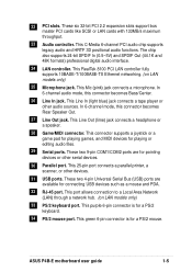
... and PDA. 32 RJ-45 port. These two 4-pin Universal Serial Bus (USB) ports are for pointing devices or other serial devices. 30 Parallel port. ASUS P4B-E motherboard user guide 1-5 22 PCI slots. This 25-pin port connects a parallel printer, a scanner, or other audio sources. These six 32-bit PCI 2.2 expansion slots support...
... and PDA. 32 RJ-45 port. These two 4-pin Universal Serial Bus (USB) ports are for pointing devices or other serial devices. 30 Parallel port. ASUS P4B-E motherboard user guide 1-5 22 PCI slots. This 25-pin port connects a parallel printer, a scanner, or other audio sources. These six 32-bit PCI 2.2 expansion slots support...

P4B-E User Manual
Page 18
... you to provide friendly voice messages and alerts during the Power-On Self-Tests (POST). ASUS POST Reporter™ P4B-E offers a new exciting feature called the ASUS POST Reporter™ to customize the voice messages, and provides multi-language support. 1-6 Chapter...Internet applications. Retention Module Base Figure 1-2 Pre-installed Heatsink Retention Module Base 1.4 Special features 1.4.1 Product highlights Latest processor technology The P4B-E motherboard supports the latest Intel Pentium 4 478/ Northwood Processor, also known as P4, via a 478-pin surface mount ZIF socket. ...
... you to provide friendly voice messages and alerts during the Power-On Self-Tests (POST). ASUS POST Reporter™ P4B-E offers a new exciting feature called the ASUS POST Reporter™ to customize the voice messages, and provides multi-language support. 1-6 Chapter...Internet applications. Retention Module Base Figure 1-2 Pre-installed Heatsink Retention Module Base 1.4 Special features 1.4.1 Product highlights Latest processor technology The P4B-E motherboard supports the latest Intel Pentium 4 478/ Northwood Processor, also known as P4, via a 478-pin surface mount ZIF socket. ...

P4B-E User Manual
Page 19
... This new feature present in the other drive. RAID 0/RAID 1 support The motherboard includes the Promise® chip PDC20265R and two extra Ultra ATA/100/66 interfaces to a second drive. ASUS P4B-E motherboard user guide 1-7 This feature requires UltraATA 100/66/33 hard disks. If one... drive to support Redundant Array of the data in the P4B-E motherboard allows you use your existing power supply rather than buying a...
... This new feature present in the other drive. RAID 0/RAID 1 support The motherboard includes the Promise® chip PDC20265R and two extra Ultra ATA/100/66 interfaces to a second drive. ASUS P4B-E motherboard user guide 1-7 This feature requires UltraATA 100/66/33 hard disks. If one... drive to support Redundant Array of the data in the P4B-E motherboard allows you use your existing power supply rather than buying a...

P4B-E User Manual
Page 20
...BIOS built-in Turbo Mode • adjustable Vcore ASUS iPanel support The motherboard supports the ASUS iPanel to provide easy connectivity, one-touch management of various peripherals, and convenient monitoring of the motherboard jumpers and connectors to 200MHz at 1MHz increments •... online transactions, editing IC-based information, and more. 1.4.2 Value-added solutions Overclocking The P4B-E overclocking features: • adjustable CPU frequency multiple in BIOS using the ASUS JumperFree™ solution • adjsutable FSB/MEM/PCI frequency ratio • Stepless Frequency ...
...BIOS built-in Turbo Mode • adjustable Vcore ASUS iPanel support The motherboard supports the ASUS iPanel to provide easy connectivity, one-touch management of various peripherals, and convenient monitoring of the motherboard jumpers and connectors to 200MHz at 1MHz increments •... online transactions, editing IC-based information, and more. 1.4.2 Value-added solutions Overclocking The P4B-E overclocking features: • adjustable CPU frequency multiple in BIOS using the ASUS JumperFree™ solution • adjsutable FSB/MEM/PCI frequency ratio • Stepless Frequency ...

P4B-E User Manual
Page 22
ASUS P4B-E motherboard
ASUS P4B-E motherboard

P4B-E User Manual
Page 23
... chassis in the correct orientation. Doing so may cause you physical injury and damage motherboard components. 2.1.1 Placement direction When installing the motherboard, make sure that you install the motherboard, study the configuration of the chassis Figure 2-1 Motherboard placement and screw holes ASUS P4B-E motherboard user guide 2-1 Refer to the image below. 2.1.2 Screw holes Place ten (10) screws...
... chassis in the correct orientation. Doing so may cause you physical injury and damage motherboard components. 2.1.1 Placement direction When installing the motherboard, make sure that you install the motherboard, study the configuration of the chassis Figure 2-1 Motherboard placement and screw holes ASUS P4B-E motherboard user guide 2-1 Refer to the image below. 2.1.2 Screw holes Place ten (10) screws...

P4B-E User Manual
Page 24
...Line ATX12V Out Line In Mic CHA_FAN In Intel 845 Memory Controller Hub (MCH) Accelerated Graphics Port (AGP) 01 23 45 P4B-E LAN_EN BCS1 BCS2 AUX CD INT_MIC HPHONE MODEM C-Media CMI8738 6CH Audio Controller PCI1 SPDIF_C PCI2 ® PCI3 AAPANEL PCI4 ... PROMISE IDE ATA-100 RAID O/I Controller RAID_IDE2 ASUS ASIC RAID_SEL RAID_EN CNRUSB0 CNRUSB1 TRPWR CR2032 3V Lithium Cell CMOS Power JEN CHAS1 SWITCH ASUS ASIC with Hardware Monitor LED1 USBPWR23 USB23 HDDLED AFPANEL PANEL RAID_IDE1 Figure 2-2 Motherboard Layout The audio CODEC, external GAME/AUDIO connectors...
...Line ATX12V Out Line In Mic CHA_FAN In Intel 845 Memory Controller Hub (MCH) Accelerated Graphics Port (AGP) 01 23 45 P4B-E LAN_EN BCS1 BCS2 AUX CD INT_MIC HPHONE MODEM C-Media CMI8738 6CH Audio Controller PCI1 SPDIF_C PCI2 ® PCI3 AAPANEL PCI4 ... PROMISE IDE ATA-100 RAID O/I Controller RAID_IDE2 ASUS ASIC RAID_SEL RAID_EN CNRUSB0 CNRUSB1 TRPWR CR2032 3V Lithium Cell CMOS Power JEN CHAS1 SWITCH ASUS ASIC with Hardware Monitor LED1 USBPWR23 USB23 HDDLED AFPANEL PANEL RAID_IDE1 Figure 2-2 Motherboard Layout The audio CODEC, external GAME/AUDIO connectors...

P4B-E User Manual
Page 25
...Card OFF Correct AGP Card LED1 ON Standby Power OFF Powered Off ASUS P4B-E motherboard user guide 2-3 Unplug the power cord from motherboard burn out caused by the edges and do so may cause severe damage to the motherboard, peripherals, and/or components. Before you install or remove any component... This LED remains off mode, a reminder that you should shut down the system before removing of the following precautions before touching any motherboard settings. 1. Failure to do not to power up. Hold components by an incorrect AGP card. 2.3 Before you proceed Take note of plugging...
...Card OFF Correct AGP Card LED1 ON Standby Power OFF Powered Off ASUS P4B-E motherboard user guide 2-3 Unplug the power cord from motherboard burn out caused by the edges and do so may cause severe damage to the motherboard, peripherals, and/or components. Before you install or remove any component... This LED remains off mode, a reminder that you should shut down the system before removing of the following precautions before touching any motherboard settings. 1. Failure to do not to power up. Hold components by an incorrect AGP card. 2.3 Before you proceed Take note of plugging...

P4B-E User Manual
Page 27
Socket Lever 90 - 100 Figure 2-6 CPU Socket Lever at 90° -100° Angle Make sure that the socket lever is lifted up to a 90°-100° angle. Locate the 478-pin ZIF socket on the motherboard. Figure 2-5 Intel 478-pin ZIF Socket 2. ASUS P4B-E motherboard user guide 2-5 Unlock the socket by pressing the lever sideways, then lift it up to install a CPU. 1. 2.4.2 Installing the CPU Follow these steps to 90°-100° angle, otherwise the CPU does not fit in completely.
Socket Lever 90 - 100 Figure 2-6 CPU Socket Lever at 90° -100° Angle Make sure that the socket lever is lifted up to a 90°-100° angle. Locate the 478-pin ZIF socket on the motherboard. Figure 2-5 Intel 478-pin ZIF Socket 2. ASUS P4B-E motherboard user guide 2-5 Unlock the socket by pressing the lever sideways, then lift it up to install a CPU. 1. 2.4.2 Installing the CPU Follow these steps to 90°-100° angle, otherwise the CPU does not fit in completely.

P4B-E User Manual
Page 29
..., making sure that you buy a boxed Intel Pentium 4 478/Northwood Processor, the package includes the heatsink, fan, and retention mechanism. ASUS P4B-E motherboard user guide 2-7 2.4.3 Installing the heatsink and fan The Intel® Pentium® 4 478/Northwood Processor requires a specially designed heatsink and...install the CPU heatsink and fan. 1. When you buy a CPU separately, make sure that the heatsink fits properly on the motherboard. The retention module base is already installed on the retention module base. CPU Heatsink Retention Module Base Figure 2-9 Installing the ...
..., making sure that you buy a boxed Intel Pentium 4 478/Northwood Processor, the package includes the heatsink, fan, and retention mechanism. ASUS P4B-E motherboard user guide 2-7 2.4.3 Installing the heatsink and fan The Intel® Pentium® 4 478/Northwood Processor requires a specially designed heatsink and...install the CPU heatsink and fan. 1. When you buy a CPU separately, make sure that the heatsink fits properly on the motherboard. The retention module base is already installed on the retention module base. CPU Heatsink Retention Module Base Figure 2-9 Installing the ...

P4B-E User Manual
Page 31
ASUS P4B-E motherboard user guide 2-9 CPU Fan Connector (CPU_FAN) Figure 2-12 CPU Fan Connector Don't forget to opposite directions. When secure, the retention locks should point to connect ... fan cable to the module base. Push down the locks on the retention mechanism to secure the heatsink and fan to the connector on the motherboard labeled CPU_FAN. Hardware monitoring errors may occur if you fail to plug this connector. 3.
ASUS P4B-E motherboard user guide 2-9 CPU Fan Connector (CPU_FAN) Figure 2-12 CPU Fan Connector Don't forget to opposite directions. When secure, the retention locks should point to connect ... fan cable to the module base. Push down the locks on the retention mechanism to secure the heatsink and fan to the connector on the motherboard labeled CPU_FAN. Hardware monitoring errors may occur if you fail to plug this connector. 3.

P4B-E User Manual
Page 32
... one direction. DO NOT force a DIMM into a socket to 3GB system memory using unbuffered ECC or non-ECC PC100/133 DIMMs. 88 Pins P4B-E ® 60 Pins P4B-E 168-Pin DIMM Sockets 20 Pins Figure 2-13 DIMM Sockets Location and SDR DIMMs DIMMs are keyed with three Single Data Rate (SDR) Dual..., 256MB, 512MB, 1GB x1 Socket 3 (Rows 4&5) 64MB, 128MB, 256MB, 512MB, 1GB x1 Total system memory (Max. 3GB) = 2-10 Chapter 2: Hardware information 2.5 System memory 2.5.1 Overview The motherboard comes with notches so that they fit in any of the following combinations.
... one direction. DO NOT force a DIMM into a socket to 3GB system memory using unbuffered ECC or non-ECC PC100/133 DIMMs. 88 Pins P4B-E ® 60 Pins P4B-E 168-Pin DIMM Sockets 20 Pins Figure 2-13 DIMM Sockets Location and SDR DIMMs DIMMs are keyed with three Single Data Rate (SDR) Dual..., 256MB, 512MB, 1GB x1 Socket 3 (Rows 4&5) 64MB, 128MB, 256MB, 512MB, 1GB x1 Total system memory (Max. 3GB) = 2-10 Chapter 2: Hardware information 2.5 System memory 2.5.1 Overview The motherboard comes with notches so that they fit in any of the following combinations.

P4B-E User Manual
Page 33
... to unplug the power supply before adding or removing DIMMs or other system components. Figure 2-14 Installing a DIMM Unlocked Retaining Clip Figure 2-15 Installed DIMM ASUS P4B-E motherboard user guide Locked Retaining Clip 2-11 2.5.3 Installing a DIMM Make sure to install a DIMM. 1. Align a DIMM on the socket such that the notches on the DIMM...
... to unplug the power supply before adding or removing DIMMs or other system components. Figure 2-14 Installing a DIMM Unlocked Retaining Clip Figure 2-15 Installed DIMM ASUS P4B-E motherboard user guide Locked Retaining Clip 2-11 2.5.3 Installing a DIMM Make sure to install a DIMM. 1. Align a DIMM on the socket such that the notches on the DIMM...


