P2L-N User Manual
Page 1
R P2L-N/P2E-N Pentium® II NLX Motherboards USER'S MANUAL
R P2L-N/P2E-N Pentium® II NLX Motherboards USER'S MANUAL
P2L-N User Manual
Page 4
...Standard CMOS Setup 38 BIOS Features Setup 41 Details of BIOS Features Setup 41 Chipset Features Setup 44 Details of the ASUS P2L-N/P2E-N Motherboard 11 Riser Card Back 11 Riser Card Front 11 III. CONTENTS I. Jumpers 14 2. Expansion Cards 22 Expansion Card... and Hardware Monitor 23 5. System Memory (DIMM 15 DIMM Memory Installation 16 3. FEATURES 8 Features of the ASUS P2L-N/P2E-N Motherboard 8 Parts of Chipset Features Setup 44 4 ASUS P2L-N/P2E-N User's Manual External Connectors 24 Front Panel Descriptions 29 Power Connection Procedures 33 IV. INTRODUCTION 7 How ...
...Standard CMOS Setup 38 BIOS Features Setup 41 Details of BIOS Features Setup 41 Chipset Features Setup 44 Details of the ASUS P2L-N/P2E-N Motherboard 11 Riser Card Back 11 Riser Card Front 11 III. CONTENTS I. Jumpers 14 2. Expansion Cards 22 Expansion Card... and Hardware Monitor 23 5. System Memory (DIMM 15 DIMM Memory Installation 16 3. FEATURES 8 Features of the ASUS P2L-N/P2E-N Motherboard 8 Parts of Chipset Features Setup 44 4 ASUS P2L-N/P2E-N User's Manual External Connectors 24 Front Panel Descriptions 29 Power Connection Procedures 33 IV. INTRODUCTION 7 How ...
P2L-N User Manual
Page 7
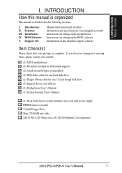
... package is divided into the following sections: I. BIOS Software: V. INTRODUCTION How this product Instructions on setting up the motherboard Instructions on setting up the BIOS software Information on -LAN 10/100 Ethernet Card (optional) ASUS P2L-N/P2E-N User's Manual 7 I . Support CD: Manual information and checklist Information and specifications concerning this manual is organized...
... package is divided into the following sections: I. BIOS Software: V. INTRODUCTION How this product Instructions on setting up the motherboard Instructions on setting up the BIOS software Information on -LAN 10/100 Ethernet Card (optional) ASUS P2L-N/P2E-N User's Manual 7 I . Support CD: Manual information and checklist Information and specifications concerning this manual is organized...
P2L-N User Manual
Page 8
...: Is equipped with EPP and ECP capabilities. FEATURES Features II. The P2L-N Motherboard adds: • Data Integrity: Error Checking and Correction (ECC) through the 440LX chipset and ECC supported DIMM. 8 ASUS P2L-N/P2E-N User's Manual FEATURES Features of either 512KB, 256KB, or 0KB...) and LS-120 floppy disk drives (3.5-inch disk drive: 120 MB, 1.44MB, 720K). Supports two drives of the ASUS P2L-N/P2E-N Motherboard The ASUS P2L-N/P2E-N motherboard is carefully designed for wireless interface. • Multi-Cache: Supports a Pentium® II processor with two connectors that ...
...: Is equipped with EPP and ECP capabilities. FEATURES Features II. The P2L-N Motherboard adds: • Data Integrity: Error Checking and Correction (ECC) through the 440LX chipset and ECC supported DIMM. 8 ASUS P2L-N/P2E-N User's Manual FEATURES Features of either 512KB, 256KB, or 0KB...) and LS-120 floppy disk drives (3.5-inch disk drive: 120 MB, 1.44MB, 720K). Supports two drives of the ASUS P2L-N/P2E-N Motherboard The ASUS P2L-N/P2E-N motherboard is carefully designed for wireless interface. • Multi-Cache: Supports a Pentium® II processor with two connectors that ...
P2L-N User Manual
Page 9
... Power Interface) is no need to upgrade current hard drives or cables. • SDRAM Optimized Performance: ASUS smart series of motherboards meet PC '97 compliancy. ASUS P2L-N/P2E-N Performance • Concurrent PCI: Concurrent PCI allows multiple PCI transfers from 264MB/s max using EDO ...virtually automatic setup. • PC '97 Compliant: Both the BIOS and hardware levels of ASUS smart series of motherboards support the new generation memory, Synchronous Dynamic Random Access Memory (SDRAM), which increases the data transfer rate from PCI mas- ASUS P2L-N/P2E-N User's Manual 9
... Power Interface) is no need to upgrade current hard drives or cables. • SDRAM Optimized Performance: ASUS smart series of motherboards meet PC '97 compliancy. ASUS P2L-N/P2E-N Performance • Concurrent PCI: Concurrent PCI allows multiple PCI transfers from 264MB/s max using EDO ...virtually automatic setup. • PC '97 Compliant: Both the BIOS and hardware levels of ASUS smart series of motherboards support the new generation memory, Synchronous Dynamic Random Access Memory (SDRAM), which increases the data transfer rate from PCI mas- ASUS P2L-N/P2E-N User's Manual 9
P2L-N User Manual
Page 10
The system resource monitor will warn the user before the system resources are used up to critical motherboard components. Suggestions will power off automatically even in the world! • System Resources Alert: Today's operating systems such as information providers. ... warn of two states, one is Sleep mode and the other is necessary to ensure proper system configuration and management. 10 ASUS P2L-N/P2E-N User's Manual II. FEATURES ASUS P2L-N/P2E-N Intelligence • Auto Fan Off: The system fans will give the user information on remotely through an external modem....
The system resource monitor will warn the user before the system resources are used up to critical motherboard components. Suggestions will power off automatically even in the world! • System Resources Alert: Today's operating systems such as information providers. ... warn of two states, one is Sleep mode and the other is necessary to ensure proper system configuration and management. 10 ASUS P2L-N/P2E-N User's Manual II. FEATURES ASUS P2L-N/P2E-N Intelligence • Auto Fan Off: The system fans will give the user information on remotely through an external modem....
P2L-N User Manual
Page 11
FEATURES Parts of the ASUS P2L-N/P2E-N Motherboard T: Parallel Conn. COM 2 Conn.(optional) Conn.(optional) Connector Joystick/MIDI Connector II. TV Out S-Video TV Out RCA VGA COM 1 B: Serial Conn. FEATURES Motherboard Parts T: PS/2 Mouse B: PS/2 Keyboard Intel 440LX or 440EX AGPset Onboard ESS Audio 2 DIMM ...Sockets SEC CPU Socket (for Pentium II) Intel PIIX4 PCIset ASUS ASIC Keyboard BIOS, Multi-I/O Onboard VGA memory (SGRAM or SDRAM...
FEATURES Parts of the ASUS P2L-N/P2E-N Motherboard T: Parallel Conn. COM 2 Conn.(optional) Conn.(optional) Connector Joystick/MIDI Connector II. TV Out S-Video TV Out RCA VGA COM 1 B: Serial Conn. FEATURES Motherboard Parts T: PS/2 Mouse B: PS/2 Keyboard Intel 440LX or 440EX AGPset Onboard ESS Audio 2 DIMM ...Sockets SEC CPU Socket (for Pentium II) Intel PIIX4 PCIset ASUS ASIC Keyboard BIOS, Multi-I/O Onboard VGA memory (SGRAM or SDRAM...
P2L-N User Manual
Page 12
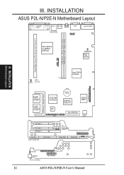
III. Riser Slot MIC Con. INSTALLATION ASUS P2L-N/P2E-N Motherboard Layout COM 1 Parallel COM 2 PS/2 RJ-45 Port RCA VGA ... R DIMM Socket 1 (64-bit, 168-pin module) DIMM Socket 2 (64-bit, 168-pin module) III. INSTALLATION Motherboard Layout 12 CPU_FAN RT4 CPU Thermal Sensor Lead Row 0 1 2 3 Intel PIIX4 Chipset CDROM Connector VGA Memory Upgrade Socket 0/1/... Pro AGP 2X VGA Chipset Impac TV2 1 AMC CMOS Power CR2032 3 Volt Cell Keyboard BIOS, RTC, & Multi-I/O ASUS ASIC Flash EEPROM (Programmable BIOS) Hardware Monitor PCI Slot 2 PCI Slot 1 ISA Slot 1 LAN LED Wake on LAN...
III. Riser Slot MIC Con. INSTALLATION ASUS P2L-N/P2E-N Motherboard Layout COM 1 Parallel COM 2 PS/2 RJ-45 Port RCA VGA ... R DIMM Socket 1 (64-bit, 168-pin module) DIMM Socket 2 (64-bit, 168-pin module) III. INSTALLATION Motherboard Layout 12 CPU_FAN RT4 CPU Thermal Sensor Lead Row 0 1 2 3 Intel PIIX4 Chipset CDROM Connector VGA Memory Upgrade Socket 0/1/... Pro AGP 2X VGA Chipset Impac TV2 1 AMC CMOS Power CR2032 3 Volt Cell Keyboard BIOS, RTC, & Multi-I/O ASUS ASIC Flash EEPROM (Programmable BIOS) Hardware Monitor PCI Slot 2 PCI Slot 1 ISA Slot 1 LAN LED Wake on LAN...
P2L-N User Manual
Page 13
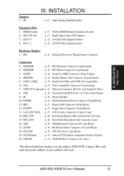
III. ASUS P2L-N/P2E-N User's Manual 13 INSTALLATION Map of Board Jumpers 1) JP1 III. LAN_LED, WOL_ p. 27 LAN Activity Connectors (2-pin & 3-pin) 14) PAN_CON p. 28 Front Panel Display ... (optional) p. 25 Television Connector (RCA & 4-pin Female S-Video) 8) USB p. 26 Universal Serial BUS Ports 1 & 2 (Two 4-pin Female) 9) IR p. 26 Infrared Module 10) POWER p. 26 NLX Motherboard Power Connector (20-pin Block) 11) IDE1 p. 27 Primary IDE Connector (40-pin Block) 12) FLOPPY p. 27 Floppy Drive Connector (34-pin Block) 13.
III. ASUS P2L-N/P2E-N User's Manual 13 INSTALLATION Map of Board Jumpers 1) JP1 III. LAN_LED, WOL_ p. 27 LAN Activity Connectors (2-pin & 3-pin) 14) PAN_CON p. 28 Front Panel Display ... (optional) p. 25 Television Connector (RCA & 4-pin Female S-Video) 8) USB p. 26 Universal Serial BUS Ports 1 & 2 (Two 4-pin Female) 9) IR p. 26 Infrared Module 10) POWER p. 26 NLX Motherboard Power Connector (20-pin Block) 11) IDE1 p. 27 Primary IDE Connector (40-pin Block) 12) FLOPPY p. 27 Floppy Drive Connector (34-pin Block) 13.
P2L-N User Manual
Page 14
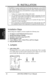
... Unit (CPU) 4. Setup the BIOS Software 1. JP1 3 2 1 Audio Enable JP1 3 2 1 Audio Disable R P2E-N Onboard Audio Setting 14 ASUS P2L-N/P2E-N User's Manual Hold components by the edges and try not to enable or disable the onboard audio. Installation Steps Before using your hands to...prevent hardware conflicts. Jumpers 1. Connect Ribbon Cables, Cabinet Wires, and Power Supply 6. Set Jumpers on the inside. 2. INSTALLATION WARNING! Computer motherboards, baseboards and components, such as the power supply case. 3. If you do not have one, touch both of your computer, you ...
... Unit (CPU) 4. Setup the BIOS Software 1. JP1 3 2 1 Audio Enable JP1 3 2 1 Audio Disable R P2E-N Onboard Audio Setting 14 ASUS P2L-N/P2E-N User's Manual Hold components by the edges and try not to enable or disable the onboard audio. Installation Steps Before using your hands to...prevent hardware conflicts. Jumpers 1. Connect Ribbon Cables, Cabinet Wires, and Power Supply 6. Set Jumpers on the inside. 2. INSTALLATION WARNING! Computer motherboards, baseboards and components, such as the power supply case. 3. If you do not have one, touch both of your computer, you ...
P2L-N User Manual
Page 15
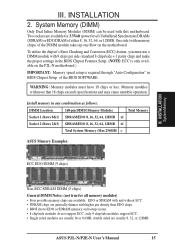
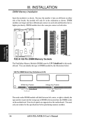
...(with memory chips) of the DIMM module takes up one Row on the P2L-N motherboard.) IMPORTANT: Memory speed setup is only available on the motherboard. III. WARNING: Memory modules must use a DIMM module with higher pin ...64, 128MB x1 Socket 2 (Rows 2&3) SDRAM/EDO 8, 16, 32, 64, 128MB x1 Total System Memory (Max 256MB) = ASUS Memory Examples: ECC EDO DIMM (9 chips) III. Install memory in the BIOS Chipset Features Setup. (NOTE: ECC is required through ...must have 18 chips or less. Memory modules with this motherboard. ASUS P2L-N/P2E-N User's Manual 15 INSTALLATION 2.
...(with memory chips) of the DIMM module takes up one Row on the P2L-N motherboard.) IMPORTANT: Memory speed setup is only available on the motherboard. III. WARNING: Memory modules must use a DIMM module with higher pin ...64, 128MB x1 Socket 2 (Rows 2&3) SDRAM/EDO 8, 16, 32, 64, 128MB x1 Total System Memory (Max 256MB) = ASUS Memory Examples: ECC EDO DIMM (9 chips) III. Install memory in the BIOS Chipset Features Setup. (NOTE: ECC is required through ...must have 18 chips or less. Memory modules with this motherboard. ASUS P2L-N/P2E-N User's Manual 15 INSTALLATION 2.
P2L-N User Manual
Page 16
... Unbuffered for the specifications before purchasing memory modules. 16 ASUS P2L-N/P2E-N User's Manual INSTALLATION System Memory Lock P2E-N 168 Pin DIMM Memory Sockets The Dual Inline Memory Module (DIMM) must ask your retailer for this motherboard. You must be inserted into the DIMM socket on ...either side of pins are supported on this motherboard. Four clock signals are different on the motherboard. III. INSTALLATION DIMM Memory Installation Insert the module(s) as shown. DIMM modules are longer and have a higher pin density...
... Unbuffered for the specifications before purchasing memory modules. 16 ASUS P2L-N/P2E-N User's Manual INSTALLATION System Memory Lock P2E-N 168 Pin DIMM Memory Sockets The Dual Inline Memory Module (DIMM) must ask your retailer for this motherboard. You must be inserted into the DIMM socket on ...either side of pins are supported on this motherboard. Four clock signals are different on the motherboard. III. INSTALLATION DIMM Memory Installation Insert the module(s) as shown. DIMM modules are longer and have a higher pin density...
P2L-N User Manual
Page 17
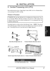
... sure that sufficient air is recommended that you install an auxiliary fan. You should be on the bottom. Central Processing Unit (CPU) This motherboard provides a Single Edge Contact (SEC) slot for your items may be slightly different.) Lock Holes (1) (2) Attach Mount Bridges (Items 1,2) ...numbers next to them for a Pentium II processor packaged in a SEC Cartridge (233-333MHz 512KB/256KB/0KB L2 Cache) CPU (Item 9) ASUS P2L-N/P2E-N User's Manual 17 Heatsink bottom Groove for the Support Top Bar Heatsink Support Base/Top Bar (Items 4-7) Pentium II Processor Heatsink ...
... sure that sufficient air is recommended that you install an auxiliary fan. You should be on the bottom. Central Processing Unit (CPU) This motherboard provides a Single Edge Contact (SEC) slot for your items may be slightly different.) Lock Holes (1) (2) Attach Mount Bridges (Items 1,2) ...numbers next to them for a Pentium II processor packaged in a SEC Cartridge (233-333MHz 512KB/256KB/0KB L2 Cache) CPU (Item 9) ASUS P2L-N/P2E-N User's Manual 17 Heatsink bottom Groove for the Support Top Bar Heatsink Support Base/Top Bar (Items 4-7) Pentium II Processor Heatsink ...
P2L-N User Manual
Page 18
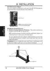
... and that the mechanism is designed to no more than 6±1 inch/pound. INSTALLATION CPU (3) Captive nut Lock holes Captive nut 18 ASUS P2L-N/P2E-N User's Manual INSTALLATION The Motherboard As Shipped Four screws should be showing next to align the notch in place. Mount the Pentium II Retention Mechanism: The retention mechanism.... Then, screw the captive nuts in the mechanism with the small rib on the board. WARNING! III. TIP: Orient the mechanism's lock holes toward the motherboard's chipsets (see motherboard layout for the location of the Intel chipset). III.
... and that the mechanism is designed to no more than 6±1 inch/pound. INSTALLATION CPU (3) Captive nut Lock holes Captive nut 18 ASUS P2L-N/P2E-N User's Manual INSTALLATION The Motherboard As Shipped Four screws should be showing next to align the notch in place. Mount the Pentium II Retention Mechanism: The retention mechanism.... Then, screw the captive nuts in the mechanism with the small rib on the board. WARNING! III. TIP: Orient the mechanism's lock holes toward the motherboard's chipsets (see motherboard layout for the location of the Intel chipset). III.
P2L-N User Manual
Page 19
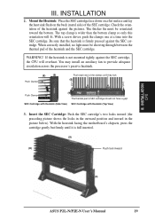
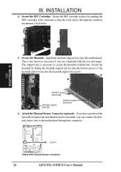
...below). INSTALLATION CPU III. With a screw driver, push the clamps one at a time into the SEC cartridge. With the heatsink facing the motherboard's chipsets, press the cartridge gently but firmly until they lock (8) Lock Lock Push Clamp (9) The thermal pad & SEC cartridge should not have ... tightly against the SEC cartridge, the CPU will fit. Be sure that the heatsink is full inserted. (9) (8) Push lock inward (3) ASUS P2L-N/P2E-N User's Manual 19 If the heatsink is wider than the bottom clamp so only this orientation will overheat. III. When correctly installed...
...below). INSTALLATION CPU III. With a screw driver, push the clamps one at a time into the SEC cartridge. With the heatsink facing the motherboard's chipsets, press the cartridge gently but firmly until they lock (8) Lock Lock Push Clamp (9) The thermal pad & SEC cartridge should not have ... tightly against the SEC cartridge, the CPU will fit. Be sure that the heatsink is full inserted. (9) (8) Push lock inward (3) ASUS P2L-N/P2E-N User's Manual 19 If the heatsink is wider than the bottom clamp so only this orientation will overheat. III. When correctly installed...
P2L-N User Manual
Page 20
...Secure the heatsink by pushing the SEC cartridge locks outward so that the lock shows through this connector. This is necessary to the motherboard through the retention mechanism's lock holes. (3) (3) (8) 5. III. Secure the SEC Cartridge: Secure the SEC cartridge in place ... locks into the motherboard. Secure the Heatsink: Install the heatsink support base into the heatsink support base posts. (9) (8) Heatsink support top bar (4) Heatsink support base (7) Heatsink support base post 6. INSTALLATION CPU R RT4 P2E-N CPU Thermal Sensor Connector 20 ASUS P2L-N/P2E-N User's...
...Secure the heatsink by pushing the SEC cartridge locks outward so that the lock shows through this connector. This is necessary to the motherboard through the retention mechanism's lock holes. (3) (3) (8) 5. III. Secure the SEC Cartridge: Secure the SEC cartridge in place ... locks into the motherboard. Secure the Heatsink: Install the heatsink support base into the heatsink support base posts. (9) (8) Heatsink support top bar (4) Heatsink support base (7) Heatsink support base post 6. INSTALLATION CPU R RT4 P2E-N CPU Thermal Sensor Connector 20 ASUS P2L-N/P2E-N User's...
P2L-N User Manual
Page 21
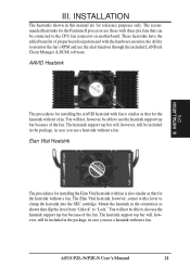
... heatsinks have the added benefits of proper heat dissipation and with fan is similar as that can be able to the CPU fan connector on motherboard. You will not be connected to also use a heatsink without a fan. The Elan Vital heatsink, however, comes with three-pin fans that for the ... heatsink support top bar will , however, still be included in the package, in case you use the heatsink support top bar because of the fan. ASUS P2L-N/P2E-N User's Manual 21 Elan Vital Heatsink III. Mount the heatsink in this manual are those with a lever to "Lock." III.
... heatsinks have the added benefits of proper heat dissipation and with fan is similar as that can be able to the CPU fan connector on motherboard. You will not be connected to also use a heatsink without a fan. The Elan Vital heatsink, however, comes with three-pin fans that for the ... heatsink support top bar will , however, still be included in the package, in case you use the heatsink support top bar because of the fan. ASUS P2L-N/P2E-N User's Manual 21 Elan Vital Heatsink III. Mount the heatsink in this manual are those with a lever to "Lock." III.
P2L-N User Manual
Page 22
...settings being used and free IRQs. If you configure the card's jumpers manually and then install it in the Windows directory to both your motherboard and expansion cards. INSTALLATION 4. Install the necessary software drivers for your expansion card, such as IRQ xx Used By ISA: Yes in ...no two devices use , leaving 6 IRQs free for Expansion Cards Some expansion cards need to operate. You may use at the same time. 22 ASUS P2L-N/P2E-N User's Manual Ensure that you removed above. 5. The original ISA expansion card design, now referred to as legacy ISA cards, requires that...
...settings being used and free IRQs. If you configure the card's jumpers manually and then install it in the Windows directory to both your motherboard and expansion cards. INSTALLATION 4. Install the necessary software drivers for your expansion card, such as IRQ xx Used By ISA: Yes in ...no two devices use , leaving 6 IRQs free for Expansion Cards Some expansion cards need to operate. You may use at the same time. 22 ASUS P2L-N/P2E-N User's Manual Ensure that you removed above. 5. The original ISA expansion card design, now referred to as legacy ISA cards, requires that...
P2L-N User Manual
Page 23
... in the PCI and PnP configuration section of your computer will occur. You can contact your PCI cards are being used and free IRQs. ASUS P2L-N/P2E-N User's Manual 23 An IRQ number is added to as the IRQ assignment process described earlier. In the PCI bus design, the ...and PnP, may use Microsoft's Diagnostic (MSD.EXE) utility included in IRQ xx Used By ISA and DMA x Used By ISA for this motherboard are in use this motherboard use a DMA (Direct Memory Access) channel. To install a PCI card, you "Resources" tab which was developed to allow automatic system ...
... in the PCI and PnP configuration section of your computer will occur. You can contact your PCI cards are being used and free IRQs. ASUS P2L-N/P2E-N User's Manual 23 An IRQ number is added to as the IRQ assignment process described earlier. In the PCI bus design, the ...and PnP, may use Microsoft's Diagnostic (MSD.EXE) utility included in IRQ xx Used By ISA and DMA x Used By ISA for this motherboard are in use this motherboard use a DMA (Direct Memory Access) channel. To install a PCI card, you "Resources" tab which was developed to allow automatic system ...
P2L-N User Manual
Page 24
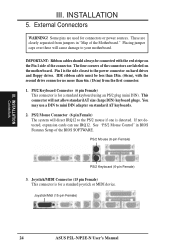
...on standard AT keyboards. 2. PS/2 Mouse Connector (6 pin Female) The system will direct IRQ12 to your motherboard. PS/2 Mouse (6-pin Female) PS/2 Keyboard (6-pin Female) 3. INSTALLATION Connectors III. Placing jumper caps ...detected. Joystick/MIDI Connector (15 pin Female) This connector is the side closest to mini DIN adapter on the motherboard. External Connectors WARNING! IDE ribbon cable must be connected with the second drive connector no more than 18in. (...used for a standard joystick or MIDI device. Joystick/Midi (15-pin Female) 24 ASUS P2L-N/P2E-N User's Manual
...on standard AT keyboards. 2. PS/2 Mouse Connector (6 pin Female) The system will direct IRQ12 to your motherboard. PS/2 Mouse (6-pin Female) PS/2 Keyboard (6-pin Female) 3. INSTALLATION Connectors III. Placing jumper caps ...detected. Joystick/MIDI Connector (15 pin Female) This connector is the side closest to mini DIN adapter on the motherboard. External Connectors WARNING! IDE ribbon cable must be connected with the second drive connector no more than 18in. (...used for a standard joystick or MIDI device. Joystick/Midi (15-pin Female) 24 ASUS P2L-N/P2E-N User's Manual


