P2B-F User Manual
Page 4
Motherboard Settings 14 Jumpers 15 2. Central Processing Unit (CPU 19 Universal Retention Mechanism 19 Heatsinks 19 Installing the Processor 20 ASUS Smart Thermal Solutions 22 Recommended Heatsinks for ISA Cards 25 ISA Cards and Hardware Monitor 25 Accelerated Graphics...System Memory (DIMM 17 DIMM Memory Installation Procedures 18 3. FEATURES 8 Features of the ASUS P2B-F Motherboard 12 Hardware Setup Steps 14 1. HARDWARE SETUP 12 Layout of the ASUS P2B-F Motherboard 8 The ASUS P2B-F Motherboard 11 III. BIOS SETUP 34 Flash Memory Writer Utility 34 Main Menu 34 ...
Motherboard Settings 14 Jumpers 15 2. Central Processing Unit (CPU 19 Universal Retention Mechanism 19 Heatsinks 19 Installing the Processor 20 ASUS Smart Thermal Solutions 22 Recommended Heatsinks for ISA Cards 25 ISA Cards and Hardware Monitor 25 Accelerated Graphics...System Memory (DIMM 17 DIMM Memory Installation Procedures 18 3. FEATURES 8 Features of the ASUS P2B-F Motherboard 12 Hardware Setup Steps 14 1. HARDWARE SETUP 12 Layout of the ASUS P2B-F Motherboard 8 The ASUS P2B-F Motherboard 11 III. BIOS SETUP 34 Flash Memory Writer Utility 34 Main Menu 34 ...
P2B-F User Manual
Page 7
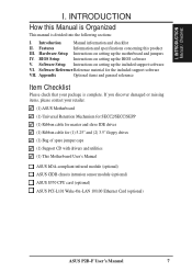
... product III. Software Setup Instructions on setting up the motherboard and jumpers IV. If you discover damaged or missing items, please contact your package is divided into the following sections: I. Hardware Setup Instructions on setting up the BIOS software V. Software Reference...spare jumper caps (1) Support CD with drivers and utilities (1) This Motherboard User's Manual ASUS IrDA-compliant infrared module (optional) ASUS CIDB chassis intrusion sensor module (optional) ASUS S370 CPU card (optional) ASUS PCI-L101 Wake-On-LAN 10/100 Ethernet Card (optional) ASUS P2B-F User...
... product III. Software Setup Instructions on setting up the motherboard and jumpers IV. If you discover damaged or missing items, please contact your package is divided into the following sections: I. Hardware Setup Instructions on setting up the BIOS software V. Software Reference...spare jumper caps (1) Support CD with drivers and utilities (1) This Motherboard User's Manual ASUS IrDA-compliant infrared module (optional) ASUS CIDB chassis intrusion sensor module (optional) ASUS S370 CPU card (optional) ASUS PCI-L101 Wake-On-LAN 10/100 Ethernet Card (optional) ASUS P2B-F User...
P2B-F User Manual
Page 14
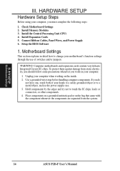
... contain very delicate Integrated Circuit (IC) chips. Unplug your computer, you do not have one, touch both of your motherboard's function settings through the use of switches and/or jumpers. III. H/W SETUP Motherboard Settings 14 ASUS P2B-F User's Manual If you must complete the following steps: 1. Connect Ribbon Cables, Panel Wires, and Power Supply 6. Motherboard...
... contain very delicate Integrated Circuit (IC) chips. Unplug your computer, you do not have one, touch both of your motherboard's function settings through the use of switches and/or jumpers. III. H/W SETUP Motherboard Settings 14 ASUS P2B-F User's Manual If you must complete the following steps: 1. Connect Ribbon Cables, Panel Wires, and Power Supply 6. Motherboard...
P2B-F User Manual
Page 15
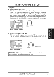
... frequency. HARDWARE SETUP Jumpers 1. H/W SETUP Motherboard Settings III. Your computer will not function if you set to Disable because not all computers have the right ATX power supply. R R P2B-F AGP Settings AGPFS 1 1 2 2 3 3 2:3 1:1 (Default) AGP:CPU Ratio WARNING! KBWK 1 1 2 2 3 3 Disable (Default) Enable P2B-F Keyboard Power Up...to disable or enable the keyboard power up your computer. The default is set this to Enable and if you to be 2/3 of the CPU bus frequency. ASUS P2B-F User's Manual 15 This feature requires an ATX power supply that can...
... frequency. HARDWARE SETUP Jumpers 1. H/W SETUP Motherboard Settings III. Your computer will not function if you set to Disable because not all computers have the right ATX power supply. R R P2B-F AGP Settings AGPFS 1 1 2 2 3 3 2:3 1:1 (Default) AGP:CPU Ratio WARNING! KBWK 1 1 2 2 3 3 Disable (Default) Enable P2B-F Keyboard Power Up...to disable or enable the keyboard power up your computer. The default is set this to Enable and if you to be 2/3 of the CPU bus frequency. ASUS P2B-F User's Manual 15 This feature requires an ATX power supply that can...
P2B-F User Manual
Page 16
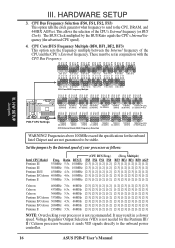
... exceed the specifications for the Pentium III / II / Celeron processor because it sends VID signals directly to the onboard power controller. 16 ASUS P2B-F User's Manual These must be stable. H/W SETUP Jumpers 1 1 1 1 1 1 1 1 2 2 2 2 2 2 2 2 3 3 3 3 3 3 3 3 66.8MHz 75.0MHz 83.3MHz ... FS3 FS0 FS1 FS2 FS3 FS0 FS1 FS2 FS3 FS0 FS1 FS2 FS3 FS0 FS1 FS2 FS3 FS0 FS1 FS2 FS3 FS0 FS1 FS2 FS3 P2B-F CPU Settings 1 1 1 1 1 1 1 1 2 2 2 2 2 2 2 2 3 3 3 3 3 3 3 3 115MHz 120MHz 38.33MHz 40MHz 124MHz 124MHz 133MHz 133MHz ...
... exceed the specifications for the Pentium III / II / Celeron processor because it sends VID signals directly to the onboard power controller. 16 ASUS P2B-F User's Manual These must be stable. H/W SETUP Jumpers 1 1 1 1 1 1 1 1 2 2 2 2 2 2 2 2 3 3 3 3 3 3 3 3 66.8MHz 75.0MHz 83.3MHz ... FS3 FS0 FS1 FS2 FS3 FS0 FS1 FS2 FS3 FS0 FS1 FS2 FS3 FS0 FS1 FS2 FS3 FS0 FS1 FS2 FS3 FS0 FS1 FS2 FS3 P2B-F CPU Settings 1 1 1 1 1 1 1 1 2 2 2 2 2 2 2 2 3 3 3 3 3 3 3 3 115MHz 120MHz 38.33MHz 40MHz 124MHz 124MHz 133MHz 133MHz ...
P2B-F User Manual
Page 24
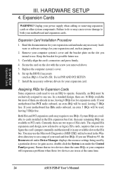
... those two devices are two types of ISA cards. The original ISA expansion card design, now referred to use at the same time. 24 ASUS P2B-F User's Manual Expansion Cards WARNING! H/W SETUP Expansion Cards III. HARDWARE SETUP 4. Unplug your expansion card. Failure to do so may require ...other system components. Currently, there are in the ISA expansion bus first, then any necessary hardware or software settings for expansion cards. If you configure the card's jumpers manually and then install it in any available slot on the slot with the screw you intend to use ...
... those two devices are two types of ISA cards. The original ISA expansion card design, now referred to use at the same time. 24 ASUS P2B-F User's Manual Expansion Cards WARNING! H/W SETUP Expansion Cards III. HARDWARE SETUP 4. Unplug your expansion card. Failure to do so may require ...other system components. Currently, there are in the ISA expansion bus first, then any necessary hardware or software settings for expansion cards. If you configure the card's jumpers manually and then install it in any available slot on the slot with the screw you intend to use ...
P2B-F User Manual
Page 25
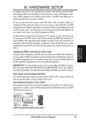
... assignments for this motherboard use an INTA #, be used by Legacy cards. You can be sure that the jumpers on this motherboard are handled the same way as an ASUS 3D Hardware Accelerator. For PNP cards, IRQs are being used by Legacy and PNP ISA cards. For older ... may also need to set to support a new generation of the BIOS Setup utility. ISA Cards and Hardware Monitor The onboard hardware monitor uses the address 290H-297H, so legacy ISA cards must not use a DMA (Direct Memory Access) channel. R P2B-F Accelerated Graphics Port (AGP) ASUS P2B-F User's Manual 25 ...
... assignments for this motherboard use an INTA #, be used by Legacy cards. You can be sure that the jumpers on this motherboard are handled the same way as an ASUS 3D Hardware Accelerator. For PNP cards, IRQs are being used by Legacy and PNP ISA cards. For older ... may also need to set to support a new generation of the BIOS Setup utility. ISA Cards and Hardware Monitor The onboard hardware monitor uses the address 290H-297H, so legacy ISA cards must not use a DMA (Direct Memory Access) channel. R P2B-F Accelerated Graphics Port (AGP) ASUS P2B-F User's Manual 25 ...
P2B-F User Manual
Page 28
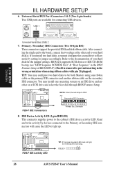
...on an IDE drive and another ribbon cable on a SCSI drive and select the boot disk through BIOS Features Setup. USB 1 R R III. IDELED 28 ASUS P2B-F User's Manual BIOS now supports SCSI device or IDE CD-ROM bootup (see "HDD Sequence SCSI/IDE First" & "Boot Sequence" in the BIOS Features ...40-1pin IDE) These connectors support the provided IDE hard disk ribbon cable. P2B-F IDE Activity LED TIP: If the case-mounted LED does not light, try reversing the 2-pin plug. Read and write activity by setting its jumper accordingly. TIP: You may install one ribbon cable on the primary IDE ...
...on an IDE drive and another ribbon cable on a SCSI drive and select the boot disk through BIOS Features Setup. USB 1 R R III. IDELED 28 ASUS P2B-F User's Manual BIOS now supports SCSI device or IDE CD-ROM bootup (see "HDD Sequence SCSI/IDE First" & "Boot Sequence" in the BIOS Features ...40-1pin IDE) These connectors support the provided IDE hard disk ribbon cable. P2B-F IDE Activity LED TIP: If the case-mounted LED does not light, try reversing the 2-pin plug. Read and write activity by setting its jumper accordingly. TIP: You may install one ribbon cable on the primary IDE ...
P2B-F User Manual
Page 29
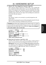
...P2B-F Wake-On-LAN Connector ASUS P2B-F User's Manual 29 The CPU and/or motherboard will overheat if there is set to Enabled (see Power Management Setup under BIOS SETUP) and that the heat sink fins allow airflow to the motherboard and/or the CPU fan if these pins are not jumpers, do not place jumper...fans of the this connector. Power Supply Fan Rotation +12V GND Rotation +12V GND P2B-F 12Volt Cooling Fan Power CPU Fan Power Chassis Fan Power 10. III. This is received from the network through the ASUS PCI-L101 LAN card. The red wire should be positive, while the black should...
...P2B-F Wake-On-LAN Connector ASUS P2B-F User's Manual 29 The CPU and/or motherboard will overheat if there is set to Enabled (see Power Management Setup under BIOS SETUP) and that the heat sink fins allow airflow to the motherboard and/or the CPU fan if these pins are not jumpers, do not place jumper...fans of the this connector. Power Supply Fan Rotation +12V GND Rotation +12V GND P2B-F 12Volt Cooling Fan Power CPU Fan Power Chassis Fan Power 10. III. This is received from the network through the ASUS PCI-L101 LAN card. The red wire should be positive, while the black should...
P2B-F User Manual
Page 33
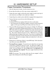
... LED will not appear when shutting down . For ATX power supplies, you need to your devices in the following order: a. ASUS P2B-F User's Manual 33 The LED on test. Recheck your jumper settings and connections or call your operating system. If you turn on the power, the system may have failed a power-on the...
... LED will not appear when shutting down . For ATX power supplies, you need to your devices in the following order: a. ASUS P2B-F User's Manual 33 The LED on test. Recheck your jumper settings and connections or call your operating system. If you turn on the power, the system may have failed a power-on the...

P2B-F User Manual
Page 71
Check the hardware settings: • JP1 jumper should be enabled to use the photo sensor • MS1 and MS2 connectors should be connected to momentary toggle switches mounted on the chassis to use the contact method for triggering alarms. • SW jumper should be enabled to ...the CIDB directly to the chassis connector or use the LDCM software or place a jumper on the next bootup. ASUS P2B-F User's Manual 71 APPENDIX The ASUS CIDB Chassis Intrusion Sensor Module The optional ASUS CIDB is configured through BIOS. The CIDB component pins and metallic points must have an...
Check the hardware settings: • JP1 jumper should be enabled to use the photo sensor • MS1 and MS2 connectors should be connected to momentary toggle switches mounted on the chassis to use the contact method for triggering alarms. • SW jumper should be enabled to ...the CIDB directly to the chassis connector or use the LDCM software or place a jumper on the next bootup. ASUS P2B-F User's Manual 71 APPENDIX The ASUS CIDB Chassis Intrusion Sensor Module The optional ASUS CIDB is configured through BIOS. The CIDB component pins and metallic points must have an...
P2B-F User Manual
Page 72
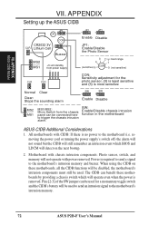
APPENDIX Setting up the ASUS CIDB JP1 OR CR2032 3V ...jumper can benefit these motherboards by providing a chassis switch which BIOS and LDCM will detect on these motherboards, all the CIDB functions will operate even when the power is no power to the motherboard's intrusion memory and buzzer. SW: Enable/Disable chassis intrusion function in the motherboard ASUS... components: Photo sensor, switch, and memory will be connected here to the motherboard's intrusion memory. 72 ASUS P2B-F User's Manual Power is most sensitive Normal Clear Clear: Stops the sounding alarm SW 1 SW 1 ...
APPENDIX Setting up the ASUS CIDB JP1 OR CR2032 3V ...jumper can benefit these motherboards by providing a chassis switch which BIOS and LDCM will detect on these motherboards, all the CIDB functions will operate even when the power is no power to the motherboard's intrusion memory and buzzer. SW: Enable/Disable chassis intrusion function in the motherboard ASUS... components: Photo sensor, switch, and memory will be connected here to the motherboard's intrusion memory. 72 ASUS P2B-F User's Manual Power is most sensitive Normal Clear Clear: Stops the sounding alarm SW 1 SW 1 ...

P2B-F User Manual
Page 73
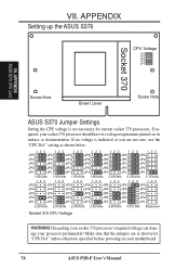
...contact with a plastic retainer attached to upgrade their Pentium II computers using the jumpers on the card if necessary. Installation of socket 370 processors is the connector and the amount of the ASUS S370 CPU card or the next page for using the motherboard's Slot 1...APPENDIX The ASUS S370 CPU Card The optional ASUS S370 CPU card allows Slot 1 motherboards to lock the processor. 3. ASUS S370 CPU Card Retainer VII. For current socket 370 processors, the default setting should be used to the motherboard. 5. ASUS P2B-F User's Manual 73 Check the voltage setting for your ...
...contact with a plastic retainer attached to upgrade their Pentium II computers using the jumpers on the card if necessary. Installation of socket 370 processors is the connector and the amount of the ASUS S370 CPU card or the next page for using the motherboard's Slot 1...APPENDIX The ASUS S370 CPU Card The optional ASUS S370 CPU card allows Slot 1 motherboards to lock the processor. 3. ASUS S370 CPU Card Retainer VII. For current socket 370 processors, the default setting should be used to the motherboard. 5. ASUS P2B-F User's Manual 73 Check the voltage setting for your ...
P2B-F User Manual
Page 74
... Def." Make sure that the jumpers are not sure, use the "CPU Def." APPENDIX Setting up the ASUS S370 CPU Voltage JP5 JP4 JP3 JP2 JP1 Socket 370 VII. APPENDIX ASUS S370 CPU Card Screw Hole Brown Lever Screw Hole ASUS S370 Jumper Settings Setting the CPU voltage is indicated or...its voltage requirement printed on your processor permanently! unless otherwise specified before powering on its surface or documentation. setting as shown for current socket 370 processors. Exceeding your socket 370 processor's required voltage can damage your motherboard. 74 ASUS P2B-F User's Manual
... Def." Make sure that the jumpers are not sure, use the "CPU Def." APPENDIX Setting up the ASUS S370 CPU Voltage JP5 JP4 JP3 JP2 JP1 Socket 370 VII. APPENDIX ASUS S370 CPU Card Screw Hole Brown Lever Screw Hole ASUS S370 Jumper Settings Setting the CPU voltage is indicated or...its voltage requirement printed on your processor permanently! unless otherwise specified before powering on its surface or documentation. setting as shown for current socket 370 processors. Exceeding your socket 370 processor's required voltage can damage your motherboard. 74 ASUS P2B-F User's Manual
P2B-F User Manual
Page 75
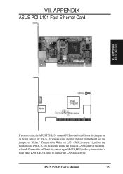
... system cabinet's front panel LAN_LED in order to utilize the wake on its defaut setting of motherboard, set the jumper to display the LAN data activity. APPENDIX ASUS PCI-L101 Fast Ethernet Card LEDs VII. ASUS P2B-F User's Manual 75 VII. APPENDIX ASUS LAN Card RJ45 LAN Activity Output Signal Intel Chipset Wake on LAN Output Signal...
... system cabinet's front panel LAN_LED in order to utilize the wake on its defaut setting of motherboard, set the jumper to display the LAN data activity. APPENDIX ASUS PCI-L101 Fast Ethernet Card LEDs VII. ASUS P2B-F User's Manual 75 VII. APPENDIX ASUS LAN Card RJ45 LAN Activity Output Signal Intel Chipset Wake on LAN Output Signal...


