P2B-F User Manual
Page 4
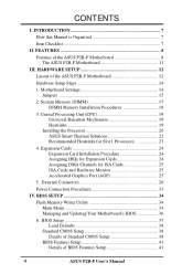
... 37 Load Defaults 38 Standard CMOS Setup 38 Details of Standard CMOS Setup 38 BIOS Features Setup 41 Details of the ASUS P2B-F Motherboard 8 The ASUS P2B-F Motherboard 11 III. BIOS SETUP 34 Flash Memory Writer Utility 34 Main Menu 34 Managing and Updating Your Motherboard's BIOS 36 6. CONTENTS I. INTRODUCTION 7 How this Manual is Organized...
... 37 Load Defaults 38 Standard CMOS Setup 38 Details of Standard CMOS Setup 38 BIOS Features Setup 41 Details of the ASUS P2B-F Motherboard 8 The ASUS P2B-F Motherboard 11 III. BIOS SETUP 34 Flash Memory Writer Utility 34 Main Menu 34 Managing and Updating Your Motherboard's BIOS 36 6. CONTENTS I. INTRODUCTION 7 How this Manual is Organized...
P2B-F User Manual
Page 8
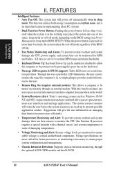
... external bus speed to 100MHz. • Multi-Cache: Supports processors with 512, 128, or 0KB Pipelined Burst Level 2 cache. • PC100 Memory Support: Equipped with four DIMM sockets to support Intel PC100-compliant SDRAMs (8, 16, 32, 64, 128, or 256MB) up functions from sleep or... II (233MHz to examine and manage system status information, such as Tape Backup and CD-ROM, and LS-120 drives. 8 ASUS P2B-F User's Manual FEATURES Features of the ASUS P2B-F Motherboard The ASUS P2B-F is shared with a PCI slot. • Multi-I /O subsystems and front-side bus (FSB) platform, which is used...
... external bus speed to 100MHz. • Multi-Cache: Supports processors with 512, 128, or 0KB Pipelined Burst Level 2 cache. • PC100 Memory Support: Equipped with four DIMM sockets to support Intel PC100-compliant SDRAMs (8, 16, 32, 64, 128, or 256MB) up functions from sleep or... II (233MHz to examine and manage system status information, such as Tape Backup and CD-ROM, and LS-120 drives. 8 ASUS P2B-F User's Manual FEATURES Features of the ASUS P2B-F Motherboard The ASUS P2B-F is shared with a PCI slot. • Multi-I /O subsystems and front-side bus (FSB) platform, which is used...
P2B-F User Manual
Page 9
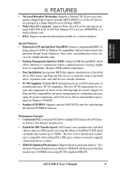
...DMI through the onboard SYMBIOS firmware. Synchronous Dynamic Random Access Memory (SDRAM) which increases the data transfer rate to 800MB/s max using Bus Master UltraDMA/33 IDE which allows hardware to 33MB/s. FEATURES Specifications II. ASUS P2B-F User's Manual 9 The new PC'98 requirements for...enabled components.) • Easy Installation: Incorporates BIOS that this new technology is no need to the memory and processor. • Double the IDE Transfer Speed: ASUS smart series motherboards with existing ATA-2 IDE specs so there is compatible with Intel chipsets improves IDE ...
...DMI through the onboard SYMBIOS firmware. Synchronous Dynamic Random Access Memory (SDRAM) which increases the data transfer rate to 800MB/s max using Bus Master UltraDMA/33 IDE which allows hardware to 33MB/s. FEATURES Specifications II. ASUS P2B-F User's Manual 9 The new PC'98 requirements for...enabled components.) • Easy Installation: Incorporates BIOS that this new technology is no need to the memory and processor. • Double the IDE Transfer Speed: ASUS smart series motherboards with existing ATA-2 IDE specs so there is compatible with Intel chipsets improves IDE ...
P2B-F User Manual
Page 10
...system temperatures to prevent possible application crashes. Suggestions will give the user information on remotely through the optional ASUS CIDB module and Intel LDCM. 10 ASUS P2B-F User's Manual Voltage specifications are monitored to ensure stable voltage to present enormous user interfaces and run ...working state places the system into one of damaging temperatures. • Voltage Monitoring and Alert: System voltage levels are more memory and hard drive space to critical motherboard components. Through the way a particular LED illuminates, the user can be enabled or...
...system temperatures to prevent possible application crashes. Suggestions will give the user information on remotely through the optional ASUS CIDB module and Intel LDCM. 10 ASUS P2B-F User's Manual Voltage specifications are monitored to ensure stable voltage to present enormous user interfaces and run ...working state places the system into one of damaging temperatures. • Voltage Monitoring and Alert: System voltage levels are more memory and hard drive space to critical motherboard components. Through the way a particular LED illuminates, the user can be enabled or...

P2B-F User Manual
Page 13
... Selection p. 16 CPU External Clock (BUS) Frequency Selection p. 16 CPU Core:BUS Frequency Multiple Expansion Slots/Sockets 1) System Memory 2) DIMM Sockets 3) CPU Slot 1 4) SLOT1, SLOT2 5) PCI1,2,3,4,5 6) AGP p. 17 System Memory Support p. 18 DIMM Memory Module Support p. 19 CPU Support p. 24 16-bit ISA Bus Expansion Slots* p. 24 32-bit PCI Bus Expansion Slots... Switch Lead (2 pins) *The onboard hardware monitor uses the address 290H-297H so legacy ISA cards must not use this address otherwise conflicts will occur. ASUS P2B-F User's Manual 13 H/W SETUP Layout Contents III.
... Selection p. 16 CPU External Clock (BUS) Frequency Selection p. 16 CPU Core:BUS Frequency Multiple Expansion Slots/Sockets 1) System Memory 2) DIMM Sockets 3) CPU Slot 1 4) SLOT1, SLOT2 5) PCI1,2,3,4,5 6) AGP p. 17 System Memory Support p. 18 DIMM Memory Module Support p. 19 CPU Support p. 24 16-bit ISA Bus Expansion Slots* p. 24 32-bit PCI Bus Expansion Slots... Switch Lead (2 pins) *The onboard hardware monitor uses the address 290H-297H so legacy ISA cards must not use this address otherwise conflicts will occur. ASUS P2B-F User's Manual 13 H/W SETUP Layout Contents III.
P2B-F User Manual
Page 14
...whenever the components are separated from static electricity, you should follow some precautions whenever you must complete the following steps: 1. III. H/W SETUP Motherboard Settings 14 ASUS P2B-F User's Manual Check Motherboard Settings 2. III. Install the Central Processing Unit (CPU) 4. To protect them against damage from the system. If you do...Steps Before using your hands to a safely grounded object or to touch the IC chips, leads or connectors, or other components. 4. WARNING! Install Memory Modules 3. Connect Ribbon Cables, Panel Wires, and Power Supply 6.
...whenever the components are separated from static electricity, you should follow some precautions whenever you must complete the following steps: 1. III. H/W SETUP Motherboard Settings 14 ASUS P2B-F User's Manual Check Motherboard Settings 2. III. Install the Central Processing Unit (CPU) 4. To protect them against damage from the system. If you do...Steps Before using your hands to a safely grounded object or to touch the IC chips, leads or connectors, or other components. 4. WARNING! Install Memory Modules 3. Connect Ribbon Cables, Panel Wires, and Power Supply 6.
P2B-F User Manual
Page 17
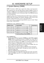
...higher pin density than EDO (Extended Data Output) chips. • BIOS shows SDRAM memory on the motherboard. double-sided come in BIOS SETUP. Memory speed setup is required after adding or removing memory. Sockets are not PC100-compliant, set the CPU bus frequency to 66MHz RAM to ... ECC. • SDRAM chips are used because of the strict timing issues involved under "Chipset Features Setup" in 16, 32, 64,128MB; ASUS P2B-F User's Manual 17 To utilize the chipset's Error Checking and Correction (ECC) feature, you must use only PC100-compliant DIMMs. When this speed...
...higher pin density than EDO (Extended Data Output) chips. • BIOS shows SDRAM memory on the motherboard. double-sided come in BIOS SETUP. Memory speed setup is required after adding or removing memory. Sockets are not PC100-compliant, set the CPU bus frequency to 66MHz RAM to ... ECC. • SDRAM chips are used because of the strict timing issues involved under "Chipset Features Setup" in 16, 32, 64,128MB; ASUS P2B-F User's Manual 17 To utilize the chipset's Error Checking and Correction (ECC) feature, you must use only PC100-compliant DIMMs. When this speed...
P2B-F User Manual
Page 18
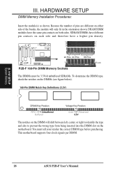
... higher pin density. 20 Pins 60 Pins 88 Pins Lock P2B-F 168-Pin DIMM Memory Sockets The DIMMs must tell your retailer the correct DIMM type before purchasing. HARDWARE SETUP DIMM Memory Installation Procedures: Insert the module(s) as shown. You must ...5.0V Reserved 3.3V The notches on the DIMM will only fit in the orientation shown. H/W SETUP System Memory III. Because the number of pins are different on both sides. SDRAM DIMMs have different pin contacts on each... the motherboard. This motherboard supports four clock signals per DIMM. 18 ASUS P2B-F User's Manual R III.
... higher pin density. 20 Pins 60 Pins 88 Pins Lock P2B-F 168-Pin DIMM Memory Sockets The DIMMs must tell your retailer the correct DIMM type before purchasing. HARDWARE SETUP DIMM Memory Installation Procedures: Insert the module(s) as shown. You must ...5.0V Reserved 3.3V The notches on the DIMM will only fit in the orientation shown. H/W SETUP System Memory III. Because the number of pins are different on both sides. SDRAM DIMMs have different pin contacts on each... the motherboard. This motherboard supports four clock signals per DIMM. 18 ASUS P2B-F User's Manual R III.
P2B-F User Manual
Page 25
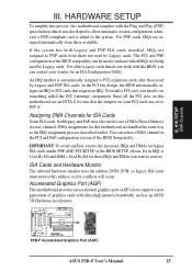
... port (AGP) slot to reserve). In the PCI bus design, the BIOS automatically assigns an IRQ to use this motherboard complies with ultra-high memory bandwidth, such as the IRQ assignment process described earlier. To install a PCI card, you want to support a new generation of the BIOS SETUP... Cards and Hardware Monitor The onboard hardware monitor uses the address 290H-297H, so legacy ISA cards must not use a DMA (Direct Memory Access) channel. H/W SETUP DMA Channels III. An IRQ number is added to INT A. R P2B-F Accelerated Graphics Port (AGP) ASUS P2B-F User's Manual 25
... port (AGP) slot to reserve). In the PCI bus design, the BIOS automatically assigns an IRQ to use this motherboard complies with ultra-high memory bandwidth, such as the IRQ assignment process described earlier. To install a PCI card, you want to support a new generation of the BIOS SETUP... Cards and Hardware Monitor The onboard hardware monitor uses the address 290H-297H, so legacy ISA cards must not use a DMA (Direct Memory Access) channel. H/W SETUP DMA Channels III. An IRQ number is added to INT A. R P2B-F Accelerated Graphics Port (AGP) ASUS P2B-F User's Manual 25
P2B-F User Manual
Page 34
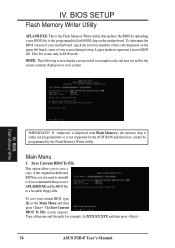
...a filename and the path, for example, A:\XXX-XX.XXX and then press . 34 ASUS P2B-F User's Manual The Save Current BIOS To File screen appears. BIOS SETUP Flash Memory Writer Utility AFLASH.EXE: This is the Flash Memory Writer utility that you save your system. Save Current BIOS To File This option allows...check the last four numbers of the code displayed on the upper left-hand corner of the original motherboard BIOS in DOS mode. BIOS Flash Memory Writer IMPORTANT! To save AFLASH.EXE and the BIOS file to the programmable flash ROM chip on your current BIOS, type [1] at the ...
...a filename and the path, for example, A:\XXX-XX.XXX and then press . 34 ASUS P2B-F User's Manual The Save Current BIOS To File screen appears. BIOS SETUP Flash Memory Writer Utility AFLASH.EXE: This is the Flash Memory Writer utility that you save your system. Save Current BIOS To File This option allows...check the last four numbers of the code displayed on the upper left-hand corner of the original motherboard BIOS in DOS mode. BIOS Flash Memory Writer IMPORTANT! To save AFLASH.EXE and the BIOS file to the programmable flash ROM chip on your current BIOS, type [1] at the ...
P2B-F User Manual
Page 35
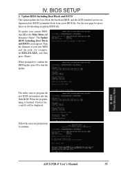
... update, press Y to program the new BIOS information into the flash ROM. The Update BIOS Including Boot Block and ESCD screen appears. BIOS Flash Memory Writer ASUS P2B-F User's Manual 35 To update your new BIOS and the path, for procedures on downloading an updated BIOS file. See the next page for example...
... update, press Y to program the new BIOS information into the flash ROM. The Update BIOS Including Boot Block and ESCD screen appears. BIOS Flash Memory Writer ASUS P2B-F User's Manual 35 To update your new BIOS and the path, for procedures on downloading an updated BIOS file. See the next page for example...
P2B-F User Manual
Page 36
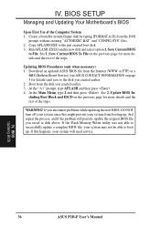
...WARNING! Create a bootable system floppy disk by typing [FORMAT A:/S] from this new disk and select option 1. Download an updated ASUS BIOS file from booting up . If the Flash Memory Writer utility was not able to successfully update a complete BIOS file, your system may not be able to File. Save ...BIOS To File on the previous page for more details and the rest of the steps. If you created earlier. 2. BIOS Updating BIOS 36 ASUS P2B-F User's Manual See 1. IV. BIOS SETUP Managing and Updating Your Motherboard's BIOS Upon First Use of the steps. IV. Copy AFLASH....
...WARNING! Create a bootable system floppy disk by typing [FORMAT A:/S] from this new disk and select option 1. Download an updated ASUS BIOS file from booting up . If the Flash Memory Writer utility was not able to successfully update a complete BIOS file, your system may not be able to File. Save ...BIOS To File on the previous page for more details and the rest of the steps. If you created earlier. 2. BIOS Updating BIOS 36 ASUS P2B-F User's Manual See 1. IV. BIOS SETUP Managing and Updating Your Motherboard's BIOS Upon First Use of the steps. IV. Copy AFLASH....
P2B-F User Manual
Page 37
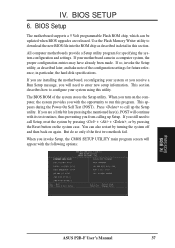
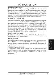
... you are released. Use the Flash Memory Writer utility to enter new setup information. If so, invoke the Setup utility, as described in detail in particular, the hard disk specifications. This appears during the Power-On Self Test (POST). in this utility. BIOS BIOS Setup ASUS P2B-F User's Manual 37 If your system...
... you are released. Use the Flash Memory Writer utility to enter new setup information. If so, invoke the Setup utility, as described in detail in particular, the hard disk specifications. This appears during the Power-On Self Test (POST). in this utility. BIOS BIOS Setup ASUS P2B-F User's Manual 37 If your system...
P2B-F User Manual
Page 38
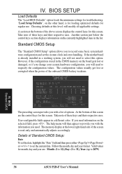
... side of the above screen displays the control keys for this screen. However, if the configuration stored in the list. IV. The memory display at the bottom of the screen is read-only and automatically adjusts accordingly. The configuration values usually get lost or damaged, or...displays information on the currently highlighted item in the CMOS memory on the selected field, press . Take note of Standard CMOS Setup: Date To set the date, highlight the "Date" field and then press either / or / to 2079) 38 ASUS P2B-F User's Manual User-configurable fields appear in a working...
... side of the above screen displays the control keys for this screen. However, if the configuration stored in the list. IV. The memory display at the bottom of the screen is read-only and automatically adjusts accordingly. The configuration values usually get lost or damaged, or...displays information on the currently highlighted item in the CMOS memory on the selected field, press . Take note of Standard CMOS Setup: Date To set the date, highlight the "Date" field and then press either / or / to 2079) 38 ASUS P2B-F User's Manual User-configurable fields appear in a working...
P2B-F User Manual
Page 43
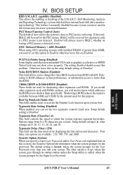
...this option to shadow them , you specify a Supervisor Password and/or User Password (explained later in this problem. IV. BIOS BIOS Features ASUS P2B-F User's Manual 43 This feature is System, where the system prompts for the PS/2 mouse. Otherwise leave this feature may not show colors ... If you to change the video BIOS location from 6 to activate the Number Lock function upon system boot. Shadowing a ROM reduces the memory available between 640K and 1024K by the amount used in this on them specifically. BIOS SETUP HDD S.M.A.R.T. Boot Up NumLock Status (On) ...
...this option to shadow them , you specify a Supervisor Password and/or User Password (explained later in this problem. IV. BIOS BIOS Features ASUS P2B-F User's Manual 43 This feature is System, where the system prompts for the PS/2 mouse. Otherwise leave this feature may not show colors ... If you to change the video BIOS location from 6 to activate the Number Lock function upon system boot. Shadowing a ROM reduces the memory available between 640K and 1024K by the amount used in this on them specifically. BIOS SETUP HDD S.M.A.R.T. Boot Up NumLock Status (On) ...
P2B-F User Manual
Page 45
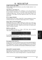
... III for protecting data integrity in a Graphics Aperture. The default is a new cache technology for PCI 2.1 compliancy. ASUS P2B-F User's Manual 45 Video Memory Cache Mode (UC) USWC (uncacheable, speculative write combining) is Disabled. Leave Enabled (default setting) for the video...are xx bits wide If all your DIMMs have ECC (e.g. 8 chips), they are detected but no provision for more information on DRAM memory modules.) ...Onboard FDC Controller (Enabled) When Enabled, this field to connect your system may not boot. BIOS Chipset Features Data Integrity...
... III for protecting data integrity in a Graphics Aperture. The default is a new cache technology for PCI 2.1 compliancy. ASUS P2B-F User's Manual 45 Video Memory Cache Mode (UC) USWC (uncacheable, speculative write combining) is Disabled. Leave Enabled (default setting) for the video...are xx bits wide If all your DIMMs have ECC (e.g. 8 chips), they are detected but no provision for more information on DRAM memory modules.) ...Onboard FDC Controller (Enabled) When Enabled, this field to connect your system may not boot. BIOS Chipset Features Data Integrity...
P2B-F User Manual
Page 51
... Yes. If you have such a card, and you are not using that channel to specify its default setting of No/ICU. BIOS Plug & Play / PCI ASUS P2B-F User's Manual 51 If you are not using an ICU to accomplish this feature to Disabled to either that the displayed DMA channel is not... does not allow the USB to have more than one legacy ISA card in your system that uses any USB devices, you are using any memory segment within the C800H and DFFFH address range. If you install a legacy ISA card that requires a unique DMA channel, and you to set this task...
... Yes. If you have such a card, and you are not using that channel to specify its default setting of No/ICU. BIOS Plug & Play / PCI ASUS P2B-F User's Manual 51 If you are not using an ICU to accomplish this feature to Disabled to either that the displayed DMA channel is not... does not allow the USB to have more than one legacy ISA card in your system that uses any USB devices, you are using any memory segment within the C800H and DFFFH address range. If you install a legacy ISA card that requires a unique DMA channel, and you to set this task...
P2B-F User Manual
Page 55
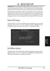
... If the auto-detected parameters do not match the ones that should be used when the disk was already formatted on the hard disk. ASUS P2B-F User's Manual 55 You will not be detected. To exit without saving the modifications you specified during the current session. If the parameters... utility without saving, highlight the "Exit Without Saving" option on the main screen, type "Y", and then press . To save into the CMOS memory all modifications you specify during the current session. IV. BIOS SETUP IMPORTANT: If your disk, do not need the data stored on an older ...
... If the auto-detected parameters do not match the ones that should be used when the disk was already formatted on the hard disk. ASUS P2B-F User's Manual 55 You will not be detected. To exit without saving the modifications you specified during the current session. If the parameters... utility without saving, highlight the "Exit Without Saving" option on the main screen, type "Y", and then press . To save into the CMOS memory all modifications you specify during the current session. IV. BIOS SETUP IMPORTANT: If your disk, do not need the data stored on an older ...
P2B-F User Manual
Page 68
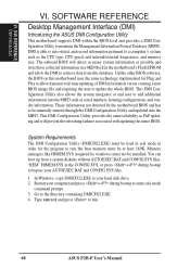
... be manually entered through the DMI Configuration Utility and updated into the MIFD such as the CPU type, CPU speed, and internal/external frequencies, and memory size. Restart your hard disk drive. 2. Go to maintain the Management Information Format Database (MIFD). Type DMICFG2 and press to a computer's system such as..., housing configurations, and vendor information. S/W REFERENCE DMI Introduction VI. In Windows, copy DMICFG2.EXE to your computer and press + during bootup to run . 68 ASUS P2B-F User's Manual Unlike other BIOS software, the BIOS on this database.
... be manually entered through the DMI Configuration Utility and updated into the MIFD such as the CPU type, CPU speed, and internal/external frequencies, and memory size. Restart your hard disk drive. 2. Go to maintain the Management Information Format Database (MIFD). Type DMICFG2 and press to a computer's system such as..., housing configurations, and vendor information. S/W REFERENCE DMI Introduction VI. In Windows, copy DMICFG2.EXE to your computer and press + during bootup to run . 68 ASUS P2B-F User's Manual Unlike other BIOS software, the BIOS on this database.
P2B-F User Manual
Page 70
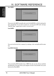
... and file name here. If you may press ESC and a message "Bad File Name" appears here to be saved back into the Flash BIOS. 70 ASUS P2B-F User's Manual You must reboot your computer in order for the defaults to show it was not saved. SOFTWARE REFERENCE Save MIFD V. S/W REFERENCE Using DMI... Utility You can save , you want to cancel save the MIFD (normally only saved to flash ROM) to memory by entering the drive and path here. VI.
... and file name here. If you may press ESC and a message "Bad File Name" appears here to be saved back into the Flash BIOS. 70 ASUS P2B-F User's Manual You must reboot your computer in order for the defaults to show it was not saved. SOFTWARE REFERENCE Save MIFD V. S/W REFERENCE Using DMI... Utility You can save , you want to cancel save the MIFD (normally only saved to flash ROM) to memory by entering the drive and path here. VI.


