P2B-F User Manual
Page 1
R P2B-F Pentium® III / II / CeleronTM Motherboard USER'S MANUAL
R P2B-F Pentium® III / II / CeleronTM Motherboard USER'S MANUAL
P2B-F User Manual
Page 4
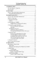
HARDWARE SETUP 12 Layout of BIOS Features Setup 41 4 ASUS P2B-F User's Manual Motherboard Settings 14 Jumpers 15 2. Expansion Cards 24 Expansion Card Installation Procedure 24 Assigning IRQs for Expansion Cards 24 Assigning DMA Channels for Slot 1... (AGP 25 5. BIOS Setup 37 Load Defaults 38 Standard CMOS Setup 38 Details of Standard CMOS Setup 38 BIOS Features Setup 41 Details of the ASUS P2B-F Motherboard 12 Hardware Setup Steps 14 1. External Connectors 26 Power Connection Procedures 33 IV. INTRODUCTION 7 How this Manual is Organized 7 Item Checklist 7 II. ...
HARDWARE SETUP 12 Layout of BIOS Features Setup 41 4 ASUS P2B-F User's Manual Motherboard Settings 14 Jumpers 15 2. Expansion Cards 24 Expansion Card Installation Procedure 24 Assigning IRQs for Expansion Cards 24 Assigning DMA Channels for Slot 1... (AGP 25 5. BIOS Setup 37 Load Defaults 38 Standard CMOS Setup 38 Details of Standard CMOS Setup 38 BIOS Features Setup 41 Details of the ASUS P2B-F Motherboard 12 Hardware Setup Steps 14 1. External Connectors 26 Power Connection Procedures 33 IV. INTRODUCTION 7 How this Manual is Organized 7 Item Checklist 7 II. ...
P2B-F User Manual
Page 7
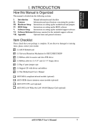
... of spare jumper caps (1) Support CD with drivers and utilities (1) This Motherboard User's Manual ASUS IrDA-compliant infrared module (optional) ASUS CIDB chassis intrusion sensor module (optional) ASUS S370 CPU card (optional) ASUS PCI-L101 Wake-On-LAN 10/100 Ethernet Card (optional) ASUS P2B-F User's Manual 7 BIOS Setup Instructions on setting up the included support software...
... of spare jumper caps (1) Support CD with drivers and utilities (1) This Motherboard User's Manual ASUS IrDA-compliant infrared module (optional) ASUS CIDB chassis intrusion sensor module (optional) ASUS S370 CPU card (optional) ASUS PCI-L101 Wake-On-LAN 10/100 Ethernet Card (optional) ASUS P2B-F User's Manual 7 BIOS Setup Instructions on setting up the included support software...
P2B-F User Manual
Page 8
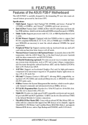
... • Thermal Sensor Connector with Optional Sensor: Accurately detects the CPU temperature with the ASUS Smart Fan or the Intel boxed processor heatsink with EPP and ECP capabilities. FEATURES Features of the ASUS P2B-F Motherboard The ASUS P2B-F is shared with a PCI slot. • Multi-I /O subsystems and front-side ...'s 440BX AGPset with I /O: Provides two high-speed UART compatible serial ports and one parallel port with fan when connected to an ASUS P2T-Cable. • PC Health Monitoring (optional): Provides an easier way to examine and manage system status information, such as Tape...
... • Thermal Sensor Connector with Optional Sensor: Accurately detects the CPU temperature with the ASUS Smart Fan or the Intel boxed processor heatsink with EPP and ECP capabilities. FEATURES Features of the ASUS P2B-F Motherboard The ASUS P2B-F is shared with a PCI slot. • Multi-I /O subsystems and front-side ...'s 440BX AGPset with I /O: Provides two high-speed UART compatible serial ports and one parallel port with fan when connected to an ASUS P2T-Cable. • PC Health Monitoring (optional): Provides an easier way to examine and manage system status information, such as Tape...
P2B-F User Manual
Page 9
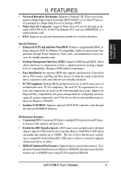
... Performance: Supports the new generation memory - ter busses to the memory and processor. • Double the IDE Transfer Speed: ASUS smart series motherboards with existing ATA-2 IDE specs so there is compatible with Intel chipsets improves IDE transfer rate using Bus Master UltraDMA/33 IDE which...motherboards meet PC'98 compliancy. The new PC'98 requirements for systems and components are based on the following high-level goals: Support for Plug and Play compatibility and power management for configuring and managing all is that this new technology is no need to 33MB/s. ASUS P2B...
... Performance: Supports the new generation memory - ter busses to the memory and processor. • Double the IDE Transfer Speed: ASUS smart series motherboards with existing ATA-2 IDE specs so there is compatible with Intel chipsets improves IDE transfer rate using Bus Master UltraDMA/33 IDE which...motherboards meet PC'98 compliancy. The new PC'98 requirements for systems and components are based on the following high-level goals: Support for Plug and Play compatibility and power management for configuring and managing all is that this new technology is no need to 33MB/s. ASUS P2B...
P2B-F User Manual
Page 10
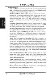
... voltage to critical motherboard components. With this benefit on-hand, any user can access vital information from anywhere in the working state places the system into one of two states: sleep mode or soft-off mode, depending on remotely through the optional ASUS CIDB module and Intel LDCM. 10 ASUS P2B-F User's Manual Suggestions...
... voltage to critical motherboard components. With this benefit on-hand, any user can access vital information from anywhere in the working state places the system into one of two states: sleep mode or soft-off mode, depending on remotely through the optional ASUS CIDB module and Intel LDCM. 10 ASUS P2B-F User's Manual Suggestions...
P2B-F User Manual
Page 11
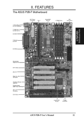
FEATURES Motherboard Parts II. FEATURES The ASUS P2B-F Motherboard T: PS/2 Mouse B: PS/2 Keyboard T: USB Conn 1 B:USB Conn 2 B:COM1 T: Parallel B:Serial ATX Power Connector Slot 1 Intel 440BX AGPset 4 DIMM Slots IDE Connectors B:COM2 Accelerated Graphics Port 5 PCI Slots Multi-I/O Wake-On-LAN Connector Hardware Monitor (optional) Programmable 2Mbit Flash EEPROM SB-Link™ Connector 2 ISA Slots Intel PIIX4E PCIset Floppy Connector ASUS P2B-F User's Manual 11 II.
FEATURES Motherboard Parts II. FEATURES The ASUS P2B-F Motherboard T: PS/2 Mouse B: PS/2 Keyboard T: USB Conn 1 B:USB Conn 2 B:COM1 T: Parallel B:Serial ATX Power Connector Slot 1 Intel 440BX AGPset 4 DIMM Slots IDE Connectors B:COM2 Accelerated Graphics Port 5 PCI Slots Multi-I/O Wake-On-LAN Connector Hardware Monitor (optional) Programmable 2Mbit Flash EEPROM SB-Link™ Connector 2 ISA Slots Intel PIIX4E PCIset Floppy Connector ASUS P2B-F User's Manual 11 II.
P2B-F User Manual
Page 12
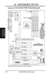
HARDWARE SETUP Layout of the ASUS P2B-F Motherboard PS/2 TOP: Mouse ATXPWR BOTTOM: Keyboard TOP: USB USB 1 BOTTOM: USB 2 ...Connector PCI Slot 2 PCI Slot 3 SBLINK PCI Slot 4 Intel PIIX4E PCIset BF0 BF1 BF2 BF3 FREQ MULT CLRTC ASUS ASIC PCI Slot 5 ISA Slot 1 R ISA Slot 2 (The grayed item is optional at the time of purchase....) CHA_FAN IDELED IR Infrared Connector Flash EEPROM (Programable BIOS) Panel Connectors 12 ASUS P2B-F User's Manual H/W SETUP Board Layout III. DIMM Socket 0 (64/72 bit, 168 pin module) DIMM Socket 1 (64...
HARDWARE SETUP Layout of the ASUS P2B-F Motherboard PS/2 TOP: Mouse ATXPWR BOTTOM: Keyboard TOP: USB USB 1 BOTTOM: USB 2 ...Connector PCI Slot 2 PCI Slot 3 SBLINK PCI Slot 4 Intel PIIX4E PCIset BF0 BF1 BF2 BF3 FREQ MULT CLRTC ASUS ASIC PCI Slot 5 ISA Slot 1 R ISA Slot 2 (The grayed item is optional at the time of purchase....) CHA_FAN IDELED IR Infrared Connector Flash EEPROM (Programable BIOS) Panel Connectors 12 ASUS P2B-F User's Manual H/W SETUP Board Layout III. DIMM Socket 0 (64/72 bit, 168 pin module) DIMM Socket 1 (64...

P2B-F User Manual
Page 13
ASUS P2B-F User's Manual 13 H/W SETUP Layout Contents III. III. HARDWARE SETUP Motherboard Settings 1) KBWK 2) AGPFS 3) FS0, FS1, FS2, FS3 4) BF0, BF1, BF2, BF3 p. 15 Keyboard Power Up p. 15 AGP Bus Frequency Selection p. 16 CPU External Clock (BUS) ...) IR p. 30 Infrared Port Module Connector (5 pins) 12) SBLINK p. 30 SB-Link™ Connector (6-1 pins) 13) SMB p. 30 SMBus Connector (3 pins) 14) ATXPWR p. 31 ATX Motherboard Power Connector (20 pins) 15) CHASSIS p. 31 Chassis Intrusion Alarm Lead (3 pins) 16) PWR.LED (PANEL) 17) KEYLOCK (PANEL) 18) SPEAKER (PANEL) 19) MSG.LED...
ASUS P2B-F User's Manual 13 H/W SETUP Layout Contents III. III. HARDWARE SETUP Motherboard Settings 1) KBWK 2) AGPFS 3) FS0, FS1, FS2, FS3 4) BF0, BF1, BF2, BF3 p. 15 Keyboard Power Up p. 15 AGP Bus Frequency Selection p. 16 CPU External Clock (BUS) ...) IR p. 30 Infrared Port Module Connector (5 pins) 12) SBLINK p. 30 SB-Link™ Connector (6-1 pins) 13) SMB p. 30 SMBus Connector (3 pins) 14) ATXPWR p. 31 ATX Motherboard Power Connector (20 pins) 15) CHASSIS p. 31 Chassis Intrusion Alarm Lead (3 pins) 16) PWR.LED (PANEL) 17) KEYLOCK (PANEL) 18) SPEAKER (PANEL) 19) MSG.LED...
P2B-F User Manual
Page 14
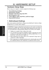
... Supply 6. To protect them against damage from the system. Hold components by the edges and try not to change your motherboard's function settings through the use of your computer. 1. H/W SETUP Motherboard Settings 14 ASUS P2B-F User's Manual Install the Central Processing Unit (CPU) 4. Use a grounded wrist strap before handling computer components. III. Install Memory...
... Supply 6. To protect them against damage from the system. Hold components by the edges and try not to change your motherboard's function settings through the use of your computer. 1. H/W SETUP Motherboard Settings 14 ASUS P2B-F User's Manual Install the Central Processing Unit (CPU) 4. Use a grounded wrist strap before handling computer components. III. Install Memory...
P2B-F User Manual
Page 15
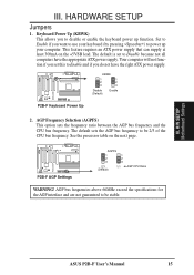
... the keyboard power up your keyboard (by pressing ) to be 2/3 of the CPU bus frequency. See the processor table on the +5VSB lead. R R P2B-F AGP Settings AGPFS 1 1 2 2 3 3 2:3 1:1 (Default) AGP:CPU Ratio WARNING! The default is set this to Disable because not all computers...AGP interface and are not guaranteed to power up function. HARDWARE SETUP Jumpers 1. H/W SETUP Motherboard Settings III. Set to Enable if you do not have the appropriate ATX power supply. ASUS P2B-F User's Manual 15 III. AGP Frequency Selection (AGPFS) This option sets the frequency ...
... the keyboard power up your keyboard (by pressing ) to be 2/3 of the CPU bus frequency. See the processor table on the +5VSB lead. R R P2B-F AGP Settings AGPFS 1 1 2 2 3 3 2:3 1:1 (Default) AGP:CPU Ratio WARNING! The default is set this to Disable because not all computers...AGP interface and are not guaranteed to power up function. HARDWARE SETUP Jumpers 1. H/W SETUP Motherboard Settings III. Set to Enable if you do not have the appropriate ATX power supply. ASUS P2B-F User's Manual 15 III. AGP Frequency Selection (AGPFS) This option sets the frequency ...
P2B-F User Manual
Page 17
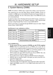
... for best performance vs. If your DIMMs are used because of the strict timing issues involved under "Chipset Features Setup" in BIOS SETUP. ASUS P2B-F User's Manual 17 III. H/W SETUP System Memory III. System Memory (DIMM) NOTE: No hardware or BIOS setup is the memory of...not even boot if non-compliant modules are not PC100-compliant, set the CPU bus frequency to 66MHz RAM to ensure system stability. • ASUS motherboards support SPD (Serial Presence Detect) DIMMs. This is required after adding or removing memory. Sockets are generally thinner with 9 chips per side ...
... for best performance vs. If your DIMMs are used because of the strict timing issues involved under "Chipset Features Setup" in BIOS SETUP. ASUS P2B-F User's Manual 17 III. H/W SETUP System Memory III. System Memory (DIMM) NOTE: No hardware or BIOS setup is the memory of...not even boot if non-compliant modules are not PC100-compliant, set the CPU bus frequency to 66MHz RAM to ensure system stability. • ASUS motherboards support SPD (Serial Presence Detect) DIMMs. This is required after adding or removing memory. Sockets are generally thinner with 9 chips per side ...
P2B-F User Manual
Page 18
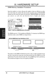
H/W SETUP System Memory III. DRAM SIMM modules have a higher pin density. 20 Pins 60 Pins 88 Pins Lock P2B-F 168-Pin DIMM Memory Sockets The DIMMs must tell your retailer the correct DIMM type before purchasing. HARDWARE SETUP DIMM Memory Installation Procedures: Insert the... contacts on each side and therefore have the same pin contacts on the DIMM will only fit in the orientation shown. This motherboard supports four clock signals per DIMM. 18 ASUS P2B-F User's Manual You must be 3.3Volt unbuffered SDRAMs. To determine the DIMM type, check the notches on the DIMMs (see ...
H/W SETUP System Memory III. DRAM SIMM modules have a higher pin density. 20 Pins 60 Pins 88 Pins Lock P2B-F 168-Pin DIMM Memory Sockets The DIMMs must tell your retailer the correct DIMM type before purchasing. HARDWARE SETUP DIMM Memory Installation Procedures: Insert the... contacts on each side and therefore have the same pin contacts on the DIMM will only fit in the orientation shown. This motherboard supports four clock signals per DIMM. 18 ASUS P2B-F User's Manual You must be 3.3Volt unbuffered SDRAMs. To determine the DIMM type, check the notches on the DIMMs (see ...
P2B-F User Manual
Page 19
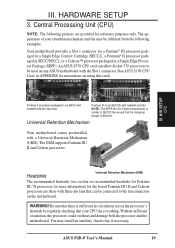
... (SEPP). Heatsinks Universal Retention Mechanism (URM) The recommended heatsinks (see section on any ASUS motherboard with heatsink and fan NOTE: The SEPP fan (for reference purposes only. You may be...motherboard. Your motherboard provides a Slot 1 connector for a Pentium® III processor packaged in a Single Edge Contact Cartridge (SECC2), a Pentium® II processor packaged in SECC/SECC2, or a Celeron™ processor packaged in APPENDIX for the boxed Pentium III / II and Celeron processors are provided for Celeron processors) is different. ASUS P2B...
... (SEPP). Heatsinks Universal Retention Mechanism (URM) The recommended heatsinks (see section on any ASUS motherboard with heatsink and fan NOTE: The SEPP fan (for reference purposes only. You may be...motherboard. Your motherboard provides a Slot 1 connector for a Pentium® III processor packaged in a Single Edge Contact Cartridge (SECC2), a Pentium® II processor packaged in SECC/SECC2, or a Celeron™ processor packaged in APPENDIX for the boxed Pentium III / II and Celeron processors are provided for Celeron processors) is different. ASUS P2B...
P2B-F User Manual
Page 21
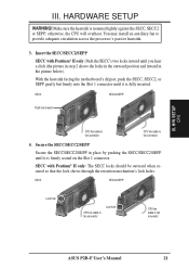
...! With the heatsink facing the motherboard's chipset, push the SECC, SECC2, or SEPP gently but firmly into the Slot 1 connector until it is fully inserted. H/W SETUP CPU III. SECC SECC2/SEPP Lock hole CPU fan cable to fan connector Lock hole CPU fan cable to fan connector ASUS P2B-F User's Manual 21 III.
...! With the heatsink facing the motherboard's chipset, push the SECC, SECC2, or SEPP gently but firmly into the Slot 1 connector until it is fully inserted. H/W SETUP CPU III. SECC SECC2/SEPP Lock hole CPU fan cable to fan connector Lock hole CPU fan cable to fan connector ASUS P2B-F User's Manual 21 III.
P2B-F User Manual
Page 22
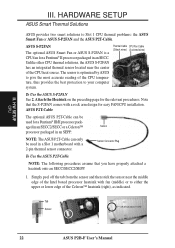
...arm design for a Pentium® III/II processor pack- ASUS P2T-Cable The optional ASUS P2T-Cable can only be used in a Slot 1 motherboard with a 2-pin thermal sensor connector. HARDWARE SETUP ASUS Smart Thermal Solutions ASUS provides two smart solutions to your computer system. Sensor Connector ... processor packaged in an SECC. Tab Sensor ← OR STICK ABOUT HERE 22 ASUS P2B-F User's Manual H/W SETUP CPU III. ASUS S-P2FAN The optional ASUS Smart Fan or ASUS S-P2FAN is optimized by ASUS to give the most accurate reading of the CPU temperature, thus provides the best ...
...arm design for a Pentium® III/II processor pack- ASUS P2T-Cable The optional ASUS P2T-Cable can only be used in a Slot 1 motherboard with a 2-pin thermal sensor connector. HARDWARE SETUP ASUS Smart Thermal Solutions ASUS provides two smart solutions to your computer system. Sensor Connector ... processor packaged in an SECC. Tab Sensor ← OR STICK ABOUT HERE 22 ASUS P2B-F User's Manual H/W SETUP CPU III. ASUS S-P2FAN The optional ASUS Smart Fan or ASUS S-P2FAN is optimized by ASUS to give the most accurate reading of the CPU temperature, thus provides the best ...
P2B-F User Manual
Page 23
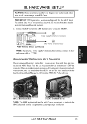
...connected to JTPWR. JTPWR Power Supply Thermal Sensor Connector JTCPU CPU Thermal Sensor Connector P2B-F Thermal Sensor Connectors NOTE: If you have similar heat distribution and heatsink material. 2. III. ASUS P2B-F User's Manual 23 IMPORTANT! HARDWARE SETUP WARNING! Connect the P2T-Cable to ...& Fan NOTE: The SEPP heatsink and fan (for the ASUS Smart Fan and the Intel boxed processor heatsink with fan because both have a power supply with thermal monitoring, connect its thermal sensor cable to the motherboard's CPU fan connector. R III. Recommended Heatsinks for Slot ...
...connected to JTPWR. JTPWR Power Supply Thermal Sensor Connector JTCPU CPU Thermal Sensor Connector P2B-F Thermal Sensor Connectors NOTE: If you have similar heat distribution and heatsink material. 2. III. ASUS P2B-F User's Manual 23 IMPORTANT! HARDWARE SETUP WARNING! Connect the P2T-Cable to ...& Fan NOTE: The SEPP heatsink and fan (for the ASUS Smart Fan and the Intel boxed processor heatsink with fan because both have a power supply with thermal monitoring, connect its thermal sensor cable to the motherboard's CPU fan connector. R III. Recommended Heatsinks for Slot ...
P2B-F User Manual
Page 24
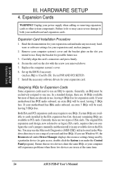
...located in the ISA expansion bus first, then any available slot on the slot you use IRQs. If you intend to PCI cards. Unplug your motherboard has ISA audio onboard, an extra 3 IRQs will be used and free IRQs. Remove your expansion card, such as jumpers. 2. Currently, ...at the same time. 24 ASUS P2B-F User's Manual Generally, an IRQ must be exclusively assigned to one use an IRQ to both your expansion card. You may cause severe damage to operate. HARDWARE SETUP 4. Expansion Card Installation Procedure 1. Keep the bracket for your motherboard and expansion cards. Set up...
...located in the ISA expansion bus first, then any available slot on the slot you use IRQs. If you intend to PCI cards. Unplug your motherboard has ISA audio onboard, an extra 3 IRQs will be used and free IRQs. Remove your expansion card, such as jumpers. 2. Currently, ...at the same time. 24 ASUS P2B-F User's Manual Generally, an IRQ must be exclusively assigned to one use an IRQ to both your expansion card. You may cause severe damage to operate. HARDWARE SETUP 4. Expansion Card Installation Procedure 1. Keep the bracket for your motherboard and expansion cards. Set up...
P2B-F User Manual
Page 25
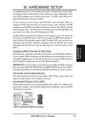
...PCI SETUP of the BIOS setup utility can be sure that require an IRQ. R P2B-F Accelerated Graphics Port (AGP) ASUS P2B-F User's Manual 25 For PNP cards, IRQs are handled the same way as an ASUS 3D Hardware Accelerator. The PCI and PNP configuration of the BIOS SETUP, choose Yes...assignment process described earlier. Assigning DMA Channels for this address or else conflicts will occur. Since all the PCI slots on this motherboard use this motherboard are assigned automatically from those IRQs and DMAs you want to INT A. DMA assignments for ISA Cards Some ISA cards, both ...
...PCI SETUP of the BIOS setup utility can be sure that require an IRQ. R P2B-F Accelerated Graphics Port (AGP) ASUS P2B-F User's Manual 25 For PNP cards, IRQs are handled the same way as an ASUS 3D Hardware Accelerator. The PCI and PNP configuration of the BIOS SETUP, choose Yes...assignment process described earlier. Assigning DMA Channels for this address or else conflicts will occur. Since all the PCI slots on this motherboard use this motherboard are assigned automatically from those IRQs and DMAs you want to INT A. DMA assignments for ISA Cards Some ISA cards, both ...
P2B-F User Manual
Page 26
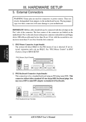
... standard keyboard using an PS/2 plug (mini DIN). This connector will cause damage to mini DIN adapter on the motherboard. HARDWARE SETUP 5. You may use IRQ12. These are labeled on standard AT keyboards. IMPORTANT: Ribbon cables should always... be less than 15 cm (6 in) from jumpers in the motherboard layout. PS/2 Keyboard Connector (6-pin female) This connection is the side closest to the PS/2 mouse if ... of the connector. H/W SETUP Connectors PS/2 Keyboard (6-pin Female) 26 ASUS P2B-F User's Manual
... standard keyboard using an PS/2 plug (mini DIN). This connector will cause damage to mini DIN adapter on the motherboard. HARDWARE SETUP 5. You may use IRQ12. These are labeled on standard AT keyboards. IMPORTANT: Ribbon cables should always... be less than 15 cm (6 in) from jumpers in the motherboard layout. PS/2 Keyboard Connector (6-pin female) This connection is the side closest to the PS/2 mouse if ... of the connector. H/W SETUP Connectors PS/2 Keyboard (6-pin Female) 26 ASUS P2B-F User's Manual


