
P2-99B User Manual
Page 1
R P2-99B Pentium® III / II / CeleronTM Motherboard USER'S MANUAL
R P2-99B Pentium® III / II / CeleronTM Motherboard USER'S MANUAL

P2-99B User Manual
Page 4
... Procedures 18 3. External Connectors 28 Power Connection Procedures 37 IV. Motherboard Settings 14 Jumpers 14 SPD Support 18 2. BIOS Setup 41 Load Defaults 42 Standard CMOS Setup 42 Details of the ASUS P2-99B Motherboard 12 Hardware Setup Steps 14 1. CONTENTS I. Central Processing Unit (CPU... 5. BIOS SETUP 38 Flash Memory Writer Utility 38 Main Menu 38 Managing and Updating Your Motherboard's BIOS 40 6. FEATURES 8 Features of the ASUS P2-99B Motherboard 8 The ASUS P2-99B Motherboard 11 III. INTRODUCTION 7 How This Manual Is Organized 7 Item Checklist 7 II.
... Procedures 18 3. External Connectors 28 Power Connection Procedures 37 IV. Motherboard Settings 14 Jumpers 14 SPD Support 18 2. BIOS Setup 41 Load Defaults 42 Standard CMOS Setup 42 Details of the ASUS P2-99B Motherboard 12 Hardware Setup Steps 14 1. CONTENTS I. Central Processing Unit (CPU... 5. BIOS SETUP 38 Flash Memory Writer Utility 38 Main Menu 38 Managing and Updating Your Motherboard's BIOS 40 6. FEATURES 8 Features of the ASUS P2-99B Motherboard 8 The ASUS P2-99B Motherboard 11 III. INTRODUCTION 7 How This Manual Is Organized 7 Item Checklist 7 II.

P2-99B User Manual
Page 5
SOFTWARE SETUP 61 ASUS Smart Motherboard Support CD 61 Installation Submenu 62 DOS Utility Submenu 63 ASUS Contact Information 64 Uninstalling Programs 65 VI. APPENDIX 81 The ASUS CIDB Chassis Intrusion Sensor Module 81 The ASUS S370 CPU Card 83 ASUS PCI-L101 Fast Ethernet Card 85 Glossary 87 ASUS P2-99B User's Manual 5 SOFTWARE REFERENCE 67 ASUS PC Probe (only...
SOFTWARE SETUP 61 ASUS Smart Motherboard Support CD 61 Installation Submenu 62 DOS Utility Submenu 63 ASUS Contact Information 64 Uninstalling Programs 65 VI. APPENDIX 81 The ASUS CIDB Chassis Intrusion Sensor Module 81 The ASUS S370 CPU Card 83 ASUS PCI-L101 Fast Ethernet Card 85 Glossary 87 ASUS P2-99B User's Manual 5 SOFTWARE REFERENCE 67 ASUS PC Probe (only...
P2-99B User Manual
Page 7
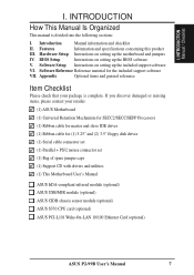
... and utilities (1) This Motherboard User's Manual ASUS IrDA-compliant infrared module (optional) ASUS USB/MIR module (optional) ASUS CIDB chassis sensor module (optional) ASUS S370 CPU card (optional) ASUS PCI-L101 Wake-On-LAN 10/100 Ethernet Card (optional) ASUS P2-99B User's Manual 7 If... support software VI. Software Setup Instructions on setting up the motherboard and jumpers IV. I . Appendix Optional items and general reference Item Checklist Please check that your retailer. (1) ASUS Motherboard (1) Universal Retention Mechanism for SECC2/SECC/SEPP Processors (1) Ribbon...
... and utilities (1) This Motherboard User's Manual ASUS IrDA-compliant infrared module (optional) ASUS USB/MIR module (optional) ASUS CIDB chassis sensor module (optional) ASUS S370 CPU card (optional) ASUS PCI-L101 Wake-On-LAN 10/100 Ethernet Card (optional) ASUS P2-99B User's Manual 7 If... support software VI. Software Setup Instructions on setting up the motherboard and jumpers IV. I . Appendix Optional items and general reference Item Checklist Please check that your retailer. (1) ASUS Motherboard (1) Universal Retention Mechanism for SECC2/SECC/SEPP Processors (1) Ribbon...

P2-99B User Manual
Page 8
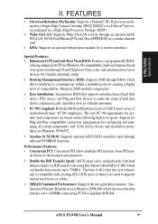
... or soft-off mode. • Thermal Sensor Connector with Optional Sensor (only w/hardware monitor): Accurately detects the CPU temperature with the ASUS Smart Fan or the Intel boxed processor heatsink with EPP and ECP capabilities. Specifications: • Multi-Speed: Supports Intel Pentium® ...system status information such as Tape Backup and CD-ROM, CDR, CD-RW and LS-120 drives. 8 ASUS P2-99B User's Manual II. FEATURES Features of the ASUS P2-99B Motherboard The ASUS P2-99B is used to the Infrared Module for wireless connections. • UltraDMA/33 Bus Master IDE: Comes with an...
... or soft-off mode. • Thermal Sensor Connector with Optional Sensor (only w/hardware monitor): Accurately detects the CPU temperature with the ASUS Smart Fan or the Intel boxed processor heatsink with EPP and ECP capabilities. Specifications: • Multi-Speed: Supports Intel Pentium® ...system status information such as Tape Backup and CD-ROM, CDR, CD-RW and LS-120 drives. 8 ASUS P2-99B User's Manual II. FEATURES Features of the ASUS P2-99B Motherboard The ASUS P2-99B is used to the Infrared Module for wireless connections. • UltraDMA/33 Bus Master IDE: Comes with an...
P2-99B User Manual
Page 9
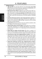
... through BIOS, which allows hardware to upgrade current hard drives or cables. • SDRAM Optimized Performance: Supports the new generation memory - ASUS P2-99B User's Manual 9 FEA TURES Specifications II. Performance Features: • Concurrent PCI: Concurrent PCI allows multiple PCI transfers from PCI mas- ... most devices for a wireless interface. ter busses to the memory and processor. • Double the IDE Transfer Speed: ASUS smart series motherboards with existing ATA-2 IDE specs so there is that supports autodetection of hard disk drives, PS/2 mouse, and Plug and...
... through BIOS, which allows hardware to upgrade current hard drives or cables. • SDRAM Optimized Performance: Supports the new generation memory - ASUS P2-99B User's Manual 9 FEA TURES Specifications II. Performance Features: • Concurrent PCI: Concurrent PCI allows multiple PCI transfers from PCI mas- ... most devices for a wireless interface. ter busses to the memory and processor. • Double the IDE Transfer Speed: ASUS smart series motherboards with existing ATA-2 IDE specs so there is that supports autodetection of hard disk drives, PS/2 mouse, and Plug and...
P2-99B User Manual
Page 10
... the user. • Remote Ring On (requires external modem): This allows a computer to be monitored for more memory and hard drive space to critical motherboard components. Voltage specifications are used up to ensure proper system configuration and management. • Chassis Intrusion Detection (only w/optional hardware monitor): Supports chassis-intrusion ... fans are monitored to ensure stable voltage to present enormous user interfaces and run large applications. With this benefit on remotely through the optional ASUS CIDB module and Intel LDCM. 10 ASUS P2-99B User's Manual
... the user. • Remote Ring On (requires external modem): This allows a computer to be monitored for more memory and hard drive space to critical motherboard components. Voltage specifications are used up to ensure proper system configuration and management. • Chassis Intrusion Detection (only w/optional hardware monitor): Supports chassis-intrusion ... fans are monitored to ensure stable voltage to present enormous user interfaces and run large applications. With this benefit on remotely through the optional ASUS CIDB module and Intel LDCM. 10 ASUS P2-99B User's Manual

P2-99B User Manual
Page 11
FEA TURES Motherboard Parts II. FEATURES The ASUS P2-99B Motherboard AT Power ATX Power Intel 440ZX AGPset Slot 1 IDE 3 DIMM Sockets Connectors Keyboard Serial Ports COM1 & COM2 USB/MIR Parallel Port Floppy Connector AGP Port 3 PCI Slots Multi-I/O Hardware Monitor (optional) Wake-On-LAN 2 ISA Slots Connector Intel PIIX4E Programmable Wake-On-Ring PCIset Flash EEPROM Connector ASUS P2-99B User's Manual 11 II.
FEA TURES Motherboard Parts II. FEATURES The ASUS P2-99B Motherboard AT Power ATX Power Intel 440ZX AGPset Slot 1 IDE 3 DIMM Sockets Connectors Keyboard Serial Ports COM1 & COM2 USB/MIR Parallel Port Floppy Connector AGP Port 3 PCI Slots Multi-I/O Hardware Monitor (optional) Wake-On-LAN 2 ISA Slots Connector Intel PIIX4E Programmable Wake-On-Ring PCIset Flash EEPROM Connector ASUS P2-99B User's Manual 11 II.

P2-99B User Manual
Page 12
... BF0 BF1 BF2 BF3 PANEL 12 ASUS P2-99B User's Manual III. HARDWARE SETUP Layout of the ASUS P2-99B Motherboard PS/2 RT3 KB-PS2KB P8 CPU_FAN Slot 1 ATXPWR ATX Power Connector AT Power Connector P9 Keyboard USB/MIR PARALLEL KBPWR COM 1 COM 2 PWR_FAN RT2 Serial ...pin module) 4 5 Accelerated Graphics Port Wake-On-LAN (WOL_CON) SMB PCI Slot 1 (PCI1) CR2032 3V Lithium Cell CMOS Power SBLINK Multi I/O CHASIS PCI Slot 2 (PCI2) P2-99B Intel PIIX4E CLRTC PCIset CHA_FAN BUS FREQ FS3 FS2 FS1 FS0 SECONDARY IDE PRIMARY IDE Hardware Monitor PCI Slot 3 (PCI3) ISA Slot 1 FREQ MULT IDELED...
... BF0 BF1 BF2 BF3 PANEL 12 ASUS P2-99B User's Manual III. HARDWARE SETUP Layout of the ASUS P2-99B Motherboard PS/2 RT3 KB-PS2KB P8 CPU_FAN Slot 1 ATXPWR ATX Power Connector AT Power Connector P9 Keyboard USB/MIR PARALLEL KBPWR COM 1 COM 2 PWR_FAN RT2 Serial ...pin module) 4 5 Accelerated Graphics Port Wake-On-LAN (WOL_CON) SMB PCI Slot 1 (PCI1) CR2032 3V Lithium Cell CMOS Power SBLINK Multi I/O CHASIS PCI Slot 2 (PCI2) P2-99B Intel PIIX4E CLRTC PCIset CHA_FAN BUS FREQ FS3 FS2 FS1 FS0 SECONDARY IDE PRIMARY IDE Hardware Monitor PCI Slot 3 (PCI3) ISA Slot 1 FREQ MULT IDELED...

P2-99B User Manual
Page 13
ASUS P2-99B User's Manual 13 III. H/W SETUP Layout Contents III. HARDWARE SETUP Motherboard Settings 1) KBPWR 2) VIO 3) VCORE 4) FS0, FS1, FS2, FS3 5) BF0, BF1, BF2, BF3 p. 14 Keyboard Power Up p. 15 VIO Selection p. 15 Voltage Regulator Output Selection p. 16 ...
ASUS P2-99B User's Manual 13 III. H/W SETUP Layout Contents III. HARDWARE SETUP Motherboard Settings 1) KBPWR 2) VIO 3) VCORE 4) FS0, FS1, FS2, FS3 5) BF0, BF1, BF2, BF3 p. 14 Keyboard Power Up p. 15 VIO Selection p. 15 Voltage Regulator Output Selection p. 16 ...

P2-99B User Manual
Page 14
... Processing Unit (CPU) 4. Set to a metal object, such as the power supply case. 3. KBPWR 123 Disable (Default) 123 Enable P2-99B R P2-99B Keyboard Power Up 14 ASUS P2-99B User's Manual III. Install Memory Modules 3. Computer motherboards and expansion cards contain very delicate Integrated Circuit (IC) chips. To protect them against damage from the system. Unplug your...
... Processing Unit (CPU) 4. Set to a metal object, such as the power supply case. 3. KBPWR 123 Disable (Default) 123 Enable P2-99B R P2-99B Keyboard Power Up 14 ASUS P2-99B User's Manual III. Install Memory Modules 3. Computer motherboards and expansion cards contain very delicate Integrated Circuit (IC) chips. To protect them against damage from the system. Unplug your...

P2-99B User Manual
Page 15
H/W SETUP Motherboard Settings III. Voltage Input/Output Selection (VIO) This jumper allows you leave these jumpers on their default settings. ASUS P2-99B User's Manual 15 P2-99B R 1 2 3 VIO 3.50Volts (Default) 1 2 3 3.66Volts P2-99B Voltage Input/Output Selection 3. Voltage Regulator Output Selection (VCORE) This jumper sets the core voltage supplied to the DRAM, chipset, AGP, and the CPU's I/O buffer...
H/W SETUP Motherboard Settings III. Voltage Input/Output Selection (VIO) This jumper allows you leave these jumpers on their default settings. ASUS P2-99B User's Manual 15 P2-99B R 1 2 3 VIO 3.50Volts (Default) 1 2 3 3.66Volts P2-99B Voltage Input/Output Selection 3. Voltage Regulator Output Selection (VCORE) This jumper sets the core voltage supplied to the DRAM, chipset, AGP, and the CPU's I/O buffer...

P2-99B User Manual
Page 16
...This option tells the clock generator what frequency to send to -Bus Frequency Multiple Settings WARNING! These must be stable. 16 ASUS P2-99B User's Manual III. H/W SETUP Motherboard Settings III. BF3 BF2 BF1 BF0 BF3 BF2 BF1 BF0 BF3 BF2 BF1 BF0 BF3 BF2 BF1 BF0 BF3 BF2 BF1 ...5x(9/2) 5.0x(5/1) 5.5x(11/2) 6.0x(6/1) 6.5x(13/2) BF3 BF2 BF1 BF0 BF3 BF2 BF1 BF0 BF3 BF2 BF1 BF0 P2-99B R 3 2 1 7.0x(7/1) 7.5x(15/2) 8.0x(8/1) P2-99B CPU Core-to the CPU, DRAM, and 440ZX AGPset. The CPU External Frequency multiplied by the Frequency Multiple equals the CPU's ...
...This option tells the clock generator what frequency to send to -Bus Frequency Multiple Settings WARNING! These must be stable. 16 ASUS P2-99B User's Manual III. H/W SETUP Motherboard Settings III. BF3 BF2 BF1 BF0 BF3 BF2 BF1 BF0 BF3 BF2 BF1 BF0 BF3 BF2 BF1 BF0 BF3 BF2 BF1 ...5x(9/2) 5.0x(5/1) 5.5x(11/2) 6.0x(6/1) 6.5x(13/2) BF3 BF2 BF1 BF0 BF3 BF2 BF1 BF0 BF3 BF2 BF1 BF0 P2-99B R 3 2 1 7.0x(7/1) 7.5x(15/2) 8.0x(8/1) P2-99B CPU Core-to the CPU, DRAM, and 440ZX AGPset. The CPU External Frequency multiplied by the Frequency Multiple equals the CPU's ...

P2-99B User Manual
Page 17
... 4.5x 100MHz 4.0x 100MHz 3.5x 100MHz (CPU Ext. Freq.) FS0 FS1 FS2 FS3 [1-2] [1-2] [1-2] [2-3] [1-2] [1-2] [1-2] [2-3] [1-2] [1-2] [1-2] [2-3] [1-2] [1-2] [1-2] [2-3] [1-2] [1-2] [1-2] [2-3] (Freq. III. Voltage Regulator Output Selection (VID) is not recommended. H/W SETUP Motherboard Settings ASUS P2-99B User's Manual 17 It may result in a slower speed. Ext. HARDWARE SETUP Set the jumpers by the Internal speed of your processor is not required...
... 4.5x 100MHz 4.0x 100MHz 3.5x 100MHz (CPU Ext. Freq.) FS0 FS1 FS2 FS3 [1-2] [1-2] [1-2] [2-3] [1-2] [1-2] [1-2] [2-3] [1-2] [1-2] [1-2] [2-3] [1-2] [1-2] [1-2] [2-3] [1-2] [1-2] [1-2] [2-3] (Freq. III. Voltage Regulator Output Selection (VID) is not recommended. H/W SETUP Motherboard Settings ASUS P2-99B User's Manual 17 It may result in a slower speed. Ext. HARDWARE SETUP Set the jumpers by the Internal speed of your processor is not required...

P2-99B User Manual
Page 18
...Notes • For the system CPU bus to 66MHz for system stability. • ASUS motherboards support SPD (Serial Presence Detect) DIMMs. This is the memory of memory is supported on bootup screen. 18 ASUS P2-99B User's Manual stability. • SDRAM chips are not PC100-compliant, set the CPU... external frequency to operate above 100MHz, use Row 3. This motherboard uses only Dual Inline Memory Modules (DIMMs). Memory speed setup ...
...Notes • For the system CPU bus to 66MHz for system stability. • ASUS motherboards support SPD (Serial Presence Detect) DIMMs. This is the memory of memory is supported on bootup screen. 18 ASUS P2-99B User's Manual stability. • SDRAM chips are not PC100-compliant, set the CPU... external frequency to operate above 100MHz, use Row 3. This motherboard uses only Dual Inline Memory Modules (DIMMs). Memory speed setup ...

P2-99B User Manual
Page 19
... on each side and therefore have different pin contacts on both sides. ASUS P2-99B User's Manual 19 You must be 3.3Volt unbuffered SDRAMs. To determine the DIMM type, check the notches on the motherboard. SDRAM DIMMs have a higher pin density. H/W SETUP System Memory DRAM...III. HARDWARE SETUP DIMM Memory Installation Procedures: Insert the module(s) as shown. Lock P2-99B R 20 Pins 60 Pins 88 Pins P2-99B 168-Pin DIMM Memory Sockets The DIMMs must tell your retailer the correct DIMM type before purchasing. This motherboard supports four clock signals per DIMM.
... on each side and therefore have different pin contacts on both sides. ASUS P2-99B User's Manual 19 You must be 3.3Volt unbuffered SDRAMs. To determine the DIMM type, check the notches on the motherboard. SDRAM DIMMs have a higher pin density. H/W SETUP System Memory DRAM...III. HARDWARE SETUP DIMM Memory Installation Procedures: Insert the module(s) as shown. Lock P2-99B R 20 Pins 60 Pins 88 Pins P2-99B 168-Pin DIMM Memory Sockets The DIMMs must tell your retailer the correct DIMM type before purchasing. This motherboard supports four clock signals per DIMM.

P2-99B User Manual
Page 21
...ASUS P2-99B User's Manual 21 The appearance of your retention mechanism and fan may install an auxiliary chassis fan, if necessary. III. H/W SETUP CPU Pentium II processor packaged in an SECC with heatsink and fan (top view) Pentium III (in APPENDIX for instructions on any ASUS motherboard ...with a Universal Retention Mechanism (URM). Universal Retention Mechanism Your motherboard comes preinstalled with the Slot 1 connector (See ASUS S370 CPU Card in an SECC2) with three-pin fans that can ...
...ASUS P2-99B User's Manual 21 The appearance of your retention mechanism and fan may install an auxiliary chassis fan, if necessary. III. H/W SETUP CPU Pentium II processor packaged in an SECC with heatsink and fan (top view) Pentium III (in APPENDIX for instructions on any ASUS motherboard ...with a Universal Retention Mechanism (URM). Universal Retention Mechanism Your motherboard comes preinstalled with the Slot 1 connector (See ASUS S370 CPU Card in an SECC2) with three-pin fans that can ...

P2-99B User Manual
Page 23
... heatsink facing the motherboard's chipset, push the SECC2, SECC, or SEPP gently but firmly into the Slot 1 connector until it is mounted tightly against the SECC, SECC2 or SEPP; SECC SECC2/SEPP Lock hole CPU fan cable to fan connector Lock hole CPU fan cable to fan connector ASUS P2-99B User's Manual 23...
... heatsink facing the motherboard's chipset, push the SECC2, SECC, or SEPP gently but firmly into the Slot 1 connector until it is mounted tightly against the SECC, SECC2 or SEPP; SECC SECC2/SEPP Lock hole CPU fan cable to fan connector Lock hole CPU fan cable to fan connector ASUS P2-99B User's Manual 23...

P2-99B User Manual
Page 24
... sensor located near the middle edge of the Intel boxed processor heatsink with a 2-pin thermal sensor connector. ASUS P2T-Cable The optional ASUS P2T-Cable can only be used in a Slot 1 motherboard with fan (middle) or to either the upper or lower edge of the CPU heat source. Sensor Sensor... in an SEPP. To Use the ASUS S-P2FAN See 2. Simply peel off the tab from the sensor and then stick the sensor near the center of the Celeron™ heatsink (right), as indicated. 24 ASUS P2-99B User's Manual The sensor is a CPU fan for motherboards with a rock arm design for the...
... sensor located near the middle edge of the Intel boxed processor heatsink with a 2-pin thermal sensor connector. ASUS P2T-Cable The optional ASUS P2T-Cable can only be used in a Slot 1 motherboard with fan (middle) or to either the upper or lower edge of the CPU heat source. Sensor Sensor... in an SEPP. To Use the ASUS S-P2FAN See 2. Simply peel off the tab from the sensor and then stick the sensor near the center of the Celeron™ heatsink (right), as indicated. 24 ASUS P2-99B User's Manual The sensor is a CPU fan for motherboards with a rock arm design for the...

P2-99B User Manual
Page 25
... cause damage to the CPU thermal sensor connector (RT2). IMPORTANT! ASUS P2-99B User's Manual 25 HARDWARE SETUP Tab Sensor ← OR STICK ABOUT HERE WARNING! III. ASUS guarantees accurate readings only for CPU P2-99B CPU Thermal Sensor Connectors NOTE: If you have similar heat distribution and...Manager (LDCM) or the ASUS PC Probe software. H/W SETUP CPU SECC Heatsink & Fan SECC2 Heatsink & Fan NOTE: The SEPP heatsink and fan (for the Slot 1 processors are those with thermal monitoring, connect its thermal sensor cable to the motherboard's CPU fan connector. Recommended...
... cause damage to the CPU thermal sensor connector (RT2). IMPORTANT! ASUS P2-99B User's Manual 25 HARDWARE SETUP Tab Sensor ← OR STICK ABOUT HERE WARNING! III. ASUS guarantees accurate readings only for CPU P2-99B CPU Thermal Sensor Connectors NOTE: If you have similar heat distribution and...Manager (LDCM) or the ASUS PC Probe software. H/W SETUP CPU SECC Heatsink & Fan SECC2 Heatsink & Fan NOTE: The SEPP heatsink and fan (for the Slot 1 processors are those with thermal monitoring, connect its thermal sensor cable to the motherboard's CPU fan connector. Recommended...


