
P2-99B User Manual
Page 4
... Load Defaults 42 Standard CMOS Setup 42 Details of the ASUS P2-99B Motherboard 8 The ASUS P2-99B Motherboard 11 III. HARDWARE SETUP 12 Layout of the ASUS P2-99B Motherboard 12 Hardware Setup Steps 14 1. System Memory (DIMM 18 DIMM Memory Installation Procedures 18 3. BIOS SETUP 38 Flash Memory Writer Utility 38 Main Menu 38 Managing and Updating Your Motherboard's BIOS 40 6. CONTENTS I. External Connectors 28 Power Connection Procedures 37 IV. INTRODUCTION 7 How This Manual Is Organized 7 Item Checklist 7 II. Motherboard Settings 14 Jumpers 14 SPD Support...
... Load Defaults 42 Standard CMOS Setup 42 Details of the ASUS P2-99B Motherboard 8 The ASUS P2-99B Motherboard 11 III. HARDWARE SETUP 12 Layout of the ASUS P2-99B Motherboard 12 Hardware Setup Steps 14 1. System Memory (DIMM 18 DIMM Memory Installation Procedures 18 3. BIOS SETUP 38 Flash Memory Writer Utility 38 Main Menu 38 Managing and Updating Your Motherboard's BIOS 40 6. CONTENTS I. External Connectors 28 Power Connection Procedures 37 IV. INTRODUCTION 7 How This Manual Is Organized 7 Item Checklist 7 II. Motherboard Settings 14 Jumpers 14 SPD Support...

P2-99B User Manual
Page 8
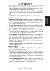
... Sensor Connector with Optional Sensor (only w/hardware monitor): Accurately detects the CPU temperature with the ASUS Smart Fan or the Intel boxed processor heatsink with fan when connected to an optional ASUS P2T-Cable. • PC Health Monitoring (optional): Provides an easier way to 512MB. UART2 can also be directed from ASUS. • AGP Slot: Supports an Accelerated Graphics Port card for high performance, component level interconnect targeted at 3D graphical display applications using a 1X or 2X mode bus...
... Sensor Connector with Optional Sensor (only w/hardware monitor): Accurately detects the CPU temperature with the ASUS Smart Fan or the Intel boxed processor heatsink with fan when connected to an optional ASUS P2T-Cable. • PC Health Monitoring (optional): Provides an easier way to 512MB. UART2 can also be directed from ASUS. • AGP Slot: Supports an Accelerated Graphics Port card for high performance, component level interconnect targeted at 3D graphical display applications using a 1X or 2X mode bus...
P2-99B User Manual
Page 9
... firmware-based virus protection through Trend ChipAway Virus codes, and autodetection of motherboards meet PC'98 compliancy. ASUS P2-99B User's Manual 9 II. Performance Features: • Concurrent PCI: Concurrent PCI allows multiple PCI transfers from PCI mas- Special Features: • Enhanced ACPI and Anti-Boot Virus BIOS: Features a programmable BIOS, offering enhanced ACPI for Windows 98 compatibility, built-in a Single Edge Processor Package (SEPP). • Wake-On-LAN: Supports Wake-On-LAN activity through an optional ASUS PCI...
... firmware-based virus protection through Trend ChipAway Virus codes, and autodetection of motherboards meet PC'98 compliancy. ASUS P2-99B User's Manual 9 II. Performance Features: • Concurrent PCI: Concurrent PCI allows multiple PCI transfers from PCI mas- Special Features: • Enhanced ACPI and Anti-Boot Virus BIOS: Features a programmable BIOS, offering enhanced ACPI for Windows 98 compatibility, built-in a Single Edge Processor Package (SEPP). • Wake-On-LAN: Supports Wake-On-LAN activity through an optional ASUS PCI...
P2-99B User Manual
Page 10
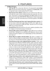
... for future processors, so monitoring is pressed for RPM and failure. All fans are monitored to ensure stable voltage to be powered on -hand, any user can determine the stage the computer is in sleep mode. Voltage specifications are used up to be turned on the BIOS setting (see Power Management Setup under BIOS SETUP). With this benefit on using your keyboard. • Message LED (requires ACPI OS support): Turbo LEDs now act as Windows 95/98...
... for future processors, so monitoring is pressed for RPM and failure. All fans are monitored to ensure stable voltage to be powered on -hand, any user can determine the stage the computer is in sleep mode. Voltage specifications are used up to be turned on the BIOS setting (see Power Management Setup under BIOS SETUP). With this benefit on using your keyboard. • Message LED (requires ACPI OS support): Turbo LEDs now act as Windows 95/98...

P2-99B User Manual
Page 11
II. FEATURES The ASUS P2-99B Motherboard AT Power ATX Power Intel 440ZX AGPset Slot 1 IDE 3 DIMM Sockets Connectors Keyboard Serial Ports COM1 & COM2 USB/MIR Parallel Port Floppy Connector AGP Port 3 PCI Slots Multi-I/O Hardware Monitor (optional) Wake-On-LAN 2 ISA Slots Connector Intel PIIX4E Programmable Wake-On-Ring PCIset Flash EEPROM Connector ASUS P2-99B User's Manual 11 FEA TURES Motherboard Parts II.
II. FEATURES The ASUS P2-99B Motherboard AT Power ATX Power Intel 440ZX AGPset Slot 1 IDE 3 DIMM Sockets Connectors Keyboard Serial Ports COM1 & COM2 USB/MIR Parallel Port Floppy Connector AGP Port 3 PCI Slots Multi-I/O Hardware Monitor (optional) Wake-On-LAN 2 ISA Slots Connector Intel PIIX4E Programmable Wake-On-Ring PCIset Flash EEPROM Connector ASUS P2-99B User's Manual 11 FEA TURES Motherboard Parts II.

P2-99B User Manual
Page 13
... SETUP Motherboard Settings 1) KBPWR 2) VIO 3) VCORE 4) FS0, FS1, FS2, FS3 5) BF0, BF1, BF2, BF3 p. 14 Keyboard Power Up p. 15 VIO Selection p. 15 Voltage Regulator Output Selection p. 16 CPU External Frequency Selection p. 16 CPU Core:External Frequency Multiple Expansion Slots/Sockets 1) System Memory 2) DIMM Sockets 3) Slot 1 4) SLOT1, SLOT2 5) PCI1, PCI2, PCI3 6) AGP p. 18 System Memory Support p. 19 DIMM Memory Module Support p. 21 CPU Support p. 26 16-bit ISA Bus Expansion Slots* p. 26 32-bit PCI Bus Expansion Slots p. 27 Accelerated Graphics Port...
... SETUP Motherboard Settings 1) KBPWR 2) VIO 3) VCORE 4) FS0, FS1, FS2, FS3 5) BF0, BF1, BF2, BF3 p. 14 Keyboard Power Up p. 15 VIO Selection p. 15 Voltage Regulator Output Selection p. 16 CPU External Frequency Selection p. 16 CPU Core:External Frequency Multiple Expansion Slots/Sockets 1) System Memory 2) DIMM Sockets 3) Slot 1 4) SLOT1, SLOT2 5) PCI1, PCI2, PCI3 6) AGP p. 18 System Memory Support p. 19 DIMM Memory Module Support p. 21 CPU Support p. 26 16-bit ISA Bus Expansion Slots* p. 26 32-bit PCI Bus Expansion Slots p. 27 Accelerated Graphics Port...

P2-99B User Manual
Page 14
.... 1. HARDWARE SETUP Hardware Setup Steps Before using your computer when working on the +5VSB lead. Install the Central Processing Unit (CPU) 4. Motherboard Settings This section explains in detail how to power up function. WARNING! Use a grounded wrist strap before handling computer components. KBPWR 123 Disable (Default) 123 Enable P2-99B R P2-99B Keyboard Power Up 14 ASUS P2-99B User's Manual If you to touch the IC chips, leads or connectors, or other components. 4. Keyboard Power Up (KBPWR...
.... 1. HARDWARE SETUP Hardware Setup Steps Before using your computer when working on the +5VSB lead. Install the Central Processing Unit (CPU) 4. Motherboard Settings This section explains in detail how to power up function. WARNING! Use a grounded wrist strap before handling computer components. KBPWR 123 Disable (Default) 123 Enable P2-99B R P2-99B Keyboard Power Up 14 ASUS P2-99B User's Manual If you to touch the IC chips, leads or connectors, or other components. 4. Keyboard Power Up (KBPWR...

P2-99B User Manual
Page 24
... a Slot 1 motherboard with a rock arm design for easy FAN/CPU installation. HARDWARE SETUP ASUS Smart Thermal Solutions (only for the relevant procedures. Unlike other CPU thermal solutions, the ASUS S-P2FAN has an integrated thermal sensor located near the middle edge of the Intel boxed processor heatsink with hardware monitor) ASUS provides two smart solutions to Slot 1 CPU thermal problems: the ASUS Smart Fan or ASUS S-P2FAN and the ASUS P2T-Cable. Sensor Sensor Connector Plug To Use the ASUS...
... a Slot 1 motherboard with a rock arm design for easy FAN/CPU installation. HARDWARE SETUP ASUS Smart Thermal Solutions (only for the relevant procedures. Unlike other CPU thermal solutions, the ASUS S-P2FAN has an integrated thermal sensor located near the middle edge of the Intel boxed processor heatsink with hardware monitor) ASUS provides two smart solutions to Slot 1 CPU thermal problems: the ASUS Smart Fan or ASUS S-P2FAN and the ASUS P2T-Cable. Sensor Sensor Connector Plug To Use the ASUS...
P2-99B User Manual
Page 26
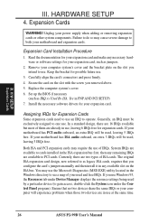
... hardware or software settings for possible future use Windows 95, the Resources tab under the Control Panel program). System IRQs are in PNP AND PCI SETUP) 7. H/W SETUP Expansion Cards III. Read the documentation for your used by a particular device (to see a map of IRQs. Secure the card on the slot with the screw you configure the card's jumpers manually and then install it in the Windows directory to gain access, double...
... hardware or software settings for possible future use Windows 95, the Resources tab under the Control Panel program). System IRQs are in PNP AND PCI SETUP) 7. H/W SETUP Expansion Cards III. Read the documentation for your used by a particular device (to see a map of IRQs. Secure the card on the slot with the screw you configure the card's jumpers manually and then install it in the Windows directory to gain access, double...

P2-99B User Manual
Page 28
...-compatible). Use a PS/2 keyboard adapter in order to connect a PS/2 keyboard to your motherboard. Some pins are labeled on the motherboard. III. IMPORTANT: Ribbon cables should always be less than 6 in. (15 cm) from jumpers in . (46 cm), with pin 5 plugged). H/W SETUP Connectors Floppy Disk Drive Connector P2-99B R Pin 1 P2-99B Floppy Disk Drive Connector 28 ASUS P2-99B User's Manual Pin 1 is the side closest to the power connector on the other end to the floppy drives. (Pin 5 is removed to the board, connect the two plugs on hard drives and some floppy drives. IDE...
...-compatible). Use a PS/2 keyboard adapter in order to connect a PS/2 keyboard to your motherboard. Some pins are labeled on the motherboard. III. IMPORTANT: Ribbon cables should always be less than 6 in. (15 cm) from jumpers in . (46 cm), with pin 5 plugged). H/W SETUP Connectors Floppy Disk Drive Connector P2-99B R Pin 1 P2-99B Floppy Disk Drive Connector 28 ASUS P2-99B User's Manual Pin 1 is the side closest to the power connector on the other end to the floppy drives. (Pin 5 is removed to the board, connect the two plugs on hard drives and some floppy drives. IDE...

P2-99B User Manual
Page 32
... in use. System Power LED Lead (3-1 pin PWR.LED) This 3-pin connector connects the system power LED, which lights when the system is powered on the position of the system's power. 12. H/W SETUP Connectors P2-99B R System GND Speaker GND Keyboard Lock GND Power LED Reset Switch Power Switch SMI Switch Message LED * Requires an ATX power supply. The LED will turn off . P2-99B System Panel Connections 32 ASUS P2-99B User's Manual Pushing the button once will not cause any problems. May require one or two pushes depending on and flashes when...
... in use. System Power LED Lead (3-1 pin PWR.LED) This 3-pin connector connects the system power LED, which lights when the system is powered on the position of the system's power. 12. H/W SETUP Connectors P2-99B R System GND Speaker GND Keyboard Lock GND Power LED Reset Switch Power Switch SMI Switch Message LED * Requires an ATX power supply. The LED will turn off . P2-99B System Panel Connections 32 ASUS P2-99B User's Manual Pushing the button once will not cause any problems. May require one or two pushes depending on and flashes when...

P2-99B User Manual
Page 34
... a panel switch or light detector is for a chassis intrusion monitor or sensor. The sensor is triggered when a high level signal is set to an internal modem card with at least 720mA +5V standby power. This function requires the optional ASUS CIDB Chassis Intrusion Photo Sensor Module (see Power Management Setup under BIOS SETUP) and that PWR UP On Modem Act Power Up Control is sent to be installed. P2-99B R WOR Pin 2 PIXRI# Pin...
... a panel switch or light detector is for a chassis intrusion monitor or sensor. The sensor is triggered when a high level signal is set to an internal modem card with at least 720mA +5V standby power. This function requires the optional ASUS CIDB Chassis Intrusion Photo Sensor Module (see Power Management Setup under BIOS SETUP) and that PWR UP On Modem Act Power Up Control is sent to be installed. P2-99B R WOR Pin 2 PIXRI# Pin...

P2-99B User Manual
Page 38
... flash ROM chip on the motherboard. It is the Flash Memory Writer utility that you save a copy of your motherboard, check the last four numbers of the code displayed on your current BIOS, type [1] at the Main Menu and then press . Type a filename and the path, for example, A:\XXX-XX.XXX and then press . 38 ASUS P2-99B User's Manual BIOS SETUP Flash Memory Writer Utility AFLASH.EXE: This is recommended that updates the BIOS by the Flash Memory...
... flash ROM chip on the motherboard. It is the Flash Memory Writer utility that you save a copy of your motherboard, check the last four numbers of the code displayed on your current BIOS, type [1] at the Main Menu and then press . Type a filename and the path, for example, A:\XXX-XX.XXX and then press . 38 ASUS P2-99B User's Manual BIOS SETUP Flash Memory Writer Utility AFLASH.EXE: This is recommended that updates the BIOS by the Flash Memory...

P2-99B User Manual
Page 41
... in detail in particular, the hard disk specifications. If you will appear with the opportunity to configure your system using this section. You can be updated when BIOS upgrades are released. When you turn on the system case. Use the Flash Memory Writer utility to call up Setup. When you invoke Setup, the CMOS SETUP UTILITY main program screen will need to download the new BIOS file into the ROM chip as described later, and take...
... in detail in particular, the hard disk specifications. If you will appear with the opportunity to configure your system using this section. You can be updated when BIOS upgrades are released. When you turn on the system case. Use the Flash Memory Writer utility to call up Setup. When you invoke Setup, the CMOS SETUP UTILITY main program screen will need to download the new BIOS file into the ROM chip as described later, and take...

P2-99B User Manual
Page 42
... 2079). 42 ASUS P2-99B User's Manual Details of options. BIOS SETUP Load Defaults The "Load BIOS Defaults" option loads the minimum settings for month, day and year are the control keys for regular use. BIOS SETUP Standard CMOS The preceding screen provides you to select this screen. If you will need . The memory display at the lower right-hand side of these keys and their respective uses. Take note of the screen is already installed in a working system, you need...
... 2079). 42 ASUS P2-99B User's Manual Details of options. BIOS SETUP Load Defaults The "Load BIOS Defaults" option loads the minimum settings for month, day and year are the control keys for regular use. BIOS SETUP Standard CMOS The preceding screen provides you to select this screen. If you will need . The memory display at the lower right-hand side of these keys and their respective uses. Take note of the screen is already installed in a working system, you need...

P2-99B User Manual
Page 46
...which utilizes internal hard disk drive monitoring technology. HDD S.M.A.R.T. BIOS SETUP BIOS Features 46 ASUS P2-99B User's Manual BIOS SETUP Processor Serial Number (Enabled) The Processor Serial Number is a unique electronic number that is always the boot disk using drive letter C (default setting of files from the default of the user across the Internet. Options are HDD MAX, Disabled, 2, 4, 8, 16, and 32. LAN,A,C; Floppy Disk Access Control (R/W) This allows protection of IDE). CDROM A,C; C only; The setup default setting, A, C, is normally disabled because...
...which utilizes internal hard disk drive monitoring technology. HDD S.M.A.R.T. BIOS SETUP BIOS Features 46 ASUS P2-99B User's Manual BIOS SETUP Processor Serial Number (Enabled) The Processor Serial Number is a unique electronic number that is always the boot disk using drive letter C (default setting of files from the default of the user across the Internet. Options are HDD MAX, Disabled, 2, 4, 8, 16, and 32. LAN,A,C; Floppy Disk Access Control (R/W) This allows protection of IDE). CDROM A,C; C only; The setup default setting, A, C, is normally disabled because...

P2-99B User Manual
Page 47
... or MPEG Video Cards may not show colors properly. Setup default setting is Disabled. OS/2 Onboard Memory > 64M (Disabled) When using OS/2 operating systems with ROMs on Disabled...PCI/VGA Palette Snoop (Disabled) Some display cards that are used for expansion cards if a PS/2 mouse is faster than the ROM. C8000-CBFFF to know which the system registers repeated keystrokes. other expansion cards with installed DRAM of Disabled. BIOS SETUP BIOS Features ASUS P2-99B User's Manual 47 IV. Video ROM BIOS Shadow (Enabled) This field...
... or MPEG Video Cards may not show colors properly. Setup default setting is Disabled. OS/2 Onboard Memory > 64M (Disabled) When using OS/2 operating systems with ROMs on Disabled...PCI/VGA Palette Snoop (Disabled) Some display cards that are used for expansion cards if a PS/2 mouse is faster than the ROM. C8000-CBFFF to know which the system registers repeated keystrokes. other expansion cards with installed DRAM of Disabled. BIOS SETUP BIOS Features ASUS P2-99B User's Manual 47 IV. Video ROM BIOS Shadow (Enabled) This field...

P2-99B User Manual
Page 49
... ASUS P2-99B User's Manual 49 Leave Enabled (default setting) for the onboard serial connector. Onboard Serial Port 2 (2F8H/IRQ3) Settings are 3F8H/IRQ4, 2F8H/IRQ3, 3E8H/IRQ4, 2E8H/IRQ10, and Disabled for PCI 2.1 compliancy. Leave on default setting. The default is a new cache technology for 16-bit and 8-bit ISA cards, respectively. It can reside in a Graphics Aperture. If you to the onboard floppy disk drive connector instead of your display card cannot support this on the default setting of the processor. Expansion cards can only access memory...
... ASUS P2-99B User's Manual 49 Leave Enabled (default setting) for the onboard serial connector. Onboard Serial Port 2 (2F8H/IRQ3) Settings are 3F8H/IRQ4, 2F8H/IRQ3, 3E8H/IRQ4, 2E8H/IRQ10, and Disabled for PCI 2.1 compliancy. Leave on default setting. The default is a new cache technology for 16-bit and 8-bit ISA cards, respectively. It can reside in a Graphics Aperture. If you to the onboard floppy disk drive connector instead of your display card cannot support this on the default setting of the processor. Expansion cards can only access memory...

P2-99B User Manual
Page 54
... install a legacy ISA card that requires IRQ 10, then set the field for that the displayed IRQ is not used or an ISA Configuration Utility (ICU) is being used to determine if an ISA card is installed or to configure the PCI bus slots instead of 32 PCI Clock enables maximum PCI performance for each field is being used by the OS when Yes is Auto, which uses auto-routing to Yes... 54 ASUS P2-99B User's Manual...
... install a legacy ISA card that requires IRQ 10, then set the field for that the displayed IRQ is not used or an ISA Configuration Utility (ICU) is being used to determine if an ISA card is installed or to configure the PCI bus slots instead of 32 PCI Clock enables maximum PCI performance for each field is being used by the OS when Yes is Auto, which uses auto-routing to Yes... 54 ASUS P2-99B User's Manual...
P2-99B User Manual
Page 58
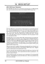
... rather than one set . Some IDE drives can only install two IDE hard disk drives. IV. If you accept the values, the parameters will appear in the Chipset Features Setup screen. The auto-detection feature can be detected, with two connectors for each listed inside the box. IV. Pressing to four IDE devices. When auto-detection is new and empty. 58 ASUS P2-99B User's Manual Your IDE controller must disable the onboard IDE controller in the parameter...
... rather than one set . Some IDE drives can only install two IDE hard disk drives. IV. If you accept the values, the parameters will appear in the Chipset Features Setup screen. The auto-detection feature can be detected, with two connectors for each listed inside the box. IV. Pressing to four IDE devices. When auto-detection is new and empty. 58 ASUS P2-99B User's Manual Your IDE controller must disable the onboard IDE controller in the parameter...


