P2-99 User Manual
Page 1
® P2-99 Pentium® III / II / CeleronTM Motherboard USER'S MANUAL
® P2-99 Pentium® III / II / CeleronTM Motherboard USER'S MANUAL
P2-99 User Manual
Page 4
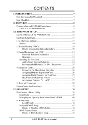
...Details of Standard CMOS Setup 42 BIOS Features Setup 45 Details of the ASUS P2-99 Motherboard 12 Hardware Setup Steps 14 1. HARDWARE SETUP 12 Layout of BIOS Features Setup 45 4 ASUS P2-99 User's Manual Central Processing Unit (CPU 21 Universal Retention Mechanism 21 ...Heatsinks 21 Installing the Processor 22 ASUS Smart Thermal Solutions 24 Recommended Heatsinks for ISA Cards 27 ISA Cards and Hardware Monitor 27 Accelerated Graphics Port (AGP 27 5. FEATURES 8 Features of the ASUS P2-99 Motherboard 8 The ASUS P2-99 Motherboard 11 III. BIOS SETUP 38 Flash...
...Details of Standard CMOS Setup 42 BIOS Features Setup 45 Details of the ASUS P2-99 Motherboard 12 Hardware Setup Steps 14 1. HARDWARE SETUP 12 Layout of BIOS Features Setup 45 4 ASUS P2-99 User's Manual Central Processing Unit (CPU 21 Universal Retention Mechanism 21 ...Heatsinks 21 Installing the Processor 22 ASUS Smart Thermal Solutions 24 Recommended Heatsinks for ISA Cards 27 ISA Cards and Hardware Monitor 27 Accelerated Graphics Port (AGP 27 5. FEATURES 8 Features of the ASUS P2-99 Motherboard 8 The ASUS P2-99 Motherboard 11 III. BIOS SETUP 38 Flash...
P2-99 User Manual
Page 7
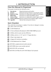
... (1) Bag of spare jumper caps (1) Support CD with drivers and utilities (1) This Motherboard User's Manual ASUS IrDA-compliant infrared module (optional) ASUS CIDB chassis sensor module (optional) ASUS S370 CPU card (optional) ASUS PCI-L101 Wake-On-LAN 10/100 Ethernet Card (optional) ASUS P2-99 User's Manual 7 Appendix Optional items and general reference Item Checklist Please check...
... (1) Bag of spare jumper caps (1) Support CD with drivers and utilities (1) This Motherboard User's Manual ASUS IrDA-compliant infrared module (optional) ASUS CIDB chassis sensor module (optional) ASUS S370 CPU card (optional) ASUS PCI-L101 Wake-On-LAN 10/100 Ethernet Card (optional) ASUS P2-99 User's Manual 7 Appendix Optional items and general reference Item Checklist Please check...
P2-99 User Manual
Page 8
... Sensor Connector w/Optional Sensor (only w/hardware monitor): Accurately detects the CPU temperature with the ASUS Smart Fan or the Intel boxed processor heatsink with fan when connected to an optional ASUS P2T-Cable. • PC Health Monitoring (optional): Provides an easier way to 450MHz),...system status information such as Tape Backup and CD-ROM, CD-R, CD-RW, and LS-120 drives. 8 ASUS P2-99 User's Manual FEATURES Features of the ASUS P2-99 Motherboard The ASUS P2-99 is used to physically transport commands and information between SMBus devices. • PCI & ISA Expansion Slots: ...
... Sensor Connector w/Optional Sensor (only w/hardware monitor): Accurately detects the CPU temperature with the ASUS Smart Fan or the Intel boxed processor heatsink with fan when connected to an optional ASUS P2T-Cable. • PC Health Monitoring (optional): Provides an easier way to 450MHz),...system status information such as Tape Backup and CD-ROM, CD-R, CD-RW, and LS-120 drives. 8 ASUS P2-99 User's Manual FEATURES Features of the ASUS P2-99 Motherboard The ASUS P2-99 is used to physically transport commands and information between SMBus devices. • PCI & ISA Expansion Slots: ...
P2-99 User Manual
Page 9
...; Enhanced ACPI and Anti-Boot Virus BIOS: Features a programmable BIOS, of motherboards meet PC'98 compliancy. ter busses to the memory and processor. • Double the IDE Transfer Speed: ASUS smart series motherboards with existing ATA-2 IDE specs so there is no need to upgrade current hard... Ethernet PCI card (See APPENDIX) or a similar ethernet card. • IrDA: Supports an optional infrared port module for a wireless interface. ASUS P2-99 User's Manual 9 Synchronous Dynamic Random Access Memory (SDRAM) which can handle data transfer up to 800MB/s max using PC100 SDRAM. FEA TURES...
...; Enhanced ACPI and Anti-Boot Virus BIOS: Features a programmable BIOS, of motherboards meet PC'98 compliancy. ter busses to the memory and processor. • Double the IDE Transfer Speed: ASUS smart series motherboards with existing ATA-2 IDE specs so there is no need to upgrade current hard... Ethernet PCI card (See APPENDIX) or a similar ethernet card. • IrDA: Supports an optional infrared port module for a wireless interface. ASUS P2-99 User's Manual 9 Synchronous Dynamic Random Access Memory (SDRAM) which can handle data transfer up to 800MB/s max using PC100 SDRAM. FEA TURES...
P2-99 User Manual
Page 10
... on by pressing the space bar on remotely through the optional ASUS CIDB module and Intel LDCM. 10 ASUS P2-99 User's Manual A simple glimpse provides useful information to the user. • Remote Ring On (requires external modem): This allows a computer to critical motherboard components. Suggestions will warn the user before the system resources are...
... on by pressing the space bar on remotely through the optional ASUS CIDB module and Intel LDCM. 10 ASUS P2-99 User's Manual A simple glimpse provides useful information to the user. • Remote Ring On (requires external modem): This allows a computer to critical motherboard components. Suggestions will warn the user before the system resources are...
P2-99 User Manual
Page 11
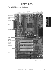
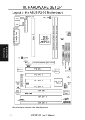
FEA TURES Motherboard Parts AGP Port Wake-On-LAN Connector 4 PCI Slots Multi-I/O & Keyboard Controller Programmable Flash EEPROM SB-Link™ Connector Hardware Monitor (optional) 3 ISA Slots Intel PIIX4E PCIset Wake-On-Ring Connector ASUS P2-99 User's Manual 11 II. FEATURES The ASUS P2-99 Motherboard T: PS/2 Mouse B: PS/2 Keyboard T: USB1 B: USB2 Serial COM1 T: Parallel B:Serial ATX Power Slot 1 Intel 440ZX AGPset Floppy IDE 2 DIMM Slots Connector Connectors Serial COM2 II.
FEA TURES Motherboard Parts AGP Port Wake-On-LAN Connector 4 PCI Slots Multi-I/O & Keyboard Controller Programmable Flash EEPROM SB-Link™ Connector Hardware Monitor (optional) 3 ISA Slots Intel PIIX4E PCIset Wake-On-Ring Connector ASUS P2-99 User's Manual 11 II. FEATURES The ASUS P2-99 Motherboard T: PS/2 Mouse B: PS/2 Keyboard T: USB1 B: USB2 Serial COM1 T: Parallel B:Serial ATX Power Slot 1 Intel 440ZX AGPset Floppy IDE 2 DIMM Slots Connector Connectors Serial COM2 II.
P2-99 User Manual
Page 12
... 3 CR2032 3V Lithium Cell (CMOS Power) CHA_FAN CLRTC Intel PIIX4E PCIset WOR BUS FREQ BF3 BF2 BF1 BF0 ASUS ASIC IR IDE LED Panel Connectors Grayed items are optional at the time of the ASUS P2-99 Motherboard T: Mouse PS/2 B: Keyboard PWR_FAN CPU_FAN Parallel Port ATX Power Connector Slot 1 USB KBPWR COM1 COM2 Intel 440ZX...
... 3 CR2032 3V Lithium Cell (CMOS Power) CHA_FAN CLRTC Intel PIIX4E PCIset WOR BUS FREQ BF3 BF2 BF1 BF0 ASUS ASIC IR IDE LED Panel Connectors Grayed items are optional at the time of the ASUS P2-99 Motherboard T: Mouse PS/2 B: Keyboard PWR_FAN CPU_FAN Parallel Port ATX Power Connector Slot 1 USB KBPWR COM1 COM2 Intel 440ZX...
P2-99 User Manual
Page 13
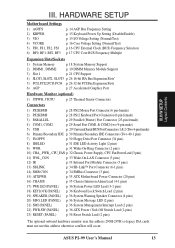
p. 34 SMBus Connector (3 pins) 15) ATXPWR p. 35 ATX Motherboard Power Connector (20 pins) 16) CHASIS p. 35 Chassis Intrusion Alarm Lead (4-1 pins) 17) PWR.LED (PANEL) 18) KEYLOCK (PANEL) 19) SPEAKER (PANEL) 20) MSG.LED (...) *The optional onboard hardware monitor uses the address 290H-297H so legacy ISA cards must not use this address otherwise conflicts will occur. ASUS P2-99 User's Manual 13 HARDWARE SETUP Motherboard Settings 1) AGPFS 2) KBPWR 3) VIO 4) VCORE 5) FS0, FS1, FS2, FS3 6) BF0, BF1, BF2, BF3 p. 14 AGP Bus Frequency Setting p. 15 Keyboard Power Up...
p. 34 SMBus Connector (3 pins) 15) ATXPWR p. 35 ATX Motherboard Power Connector (20 pins) 16) CHASIS p. 35 Chassis Intrusion Alarm Lead (4-1 pins) 17) PWR.LED (PANEL) 18) KEYLOCK (PANEL) 19) SPEAKER (PANEL) 20) MSG.LED (...) *The optional onboard hardware monitor uses the address 290H-297H so legacy ISA cards must not use this address otherwise conflicts will occur. ASUS P2-99 User's Manual 13 HARDWARE SETUP Motherboard Settings 1) AGPFS 2) KBPWR 3) VIO 4) VCORE 5) FS0, FS1, FS2, FS3 6) BF0, BF1, BF2, BF3 p. 14 AGP Bus Frequency Setting p. 15 Keyboard Power Up...

P2-99 User Manual
Page 14
... Integrated Circuit (IC) chips. H/W SETUP Motherboard Settings III. Unplug your motherboard's function settings through the use of your computer. 1. Motherboard Settings This section explains in detail how to change your computer when working on the bag that came with the component whenever the components are not guaranteed to be stable. 14 ASUS P2-99 User's Manual
... Integrated Circuit (IC) chips. H/W SETUP Motherboard Settings III. Unplug your motherboard's function settings through the use of your computer. 1. Motherboard Settings This section explains in detail how to change your computer when working on the bag that came with the component whenever the components are not guaranteed to be stable. 14 ASUS P2-99 User's Manual

P2-99 User Manual
Page 15
...SETUP Motherboard Settings III. This feature requires an ATX power supply that can supply at least 300mA on default setting of Normal. I/O Voltage Setting (VIO) This jumper allows you to Disable because not all computers have the right ATX power supply. VIO 3 2 1 Normal 3 2 1 Test P2-99 P2-99 I... this jumper to power up function. KBPWR 3 2 1 Disable 3 2 1 Enable P2-99 P2-99 Keyboard Power Up Setting 3. III. Set to the DRAM, chipset, AGP, and the CPU's I /O Voltage Setting ASUS P2-99 User's Manual 15 Keyboard Power Up Setting (KBPWR) This allows you to select the ...
...SETUP Motherboard Settings III. This feature requires an ATX power supply that can supply at least 300mA on default setting of Normal. I/O Voltage Setting (VIO) This jumper allows you to Disable because not all computers have the right ATX power supply. VIO 3 2 1 Normal 3 2 1 Test P2-99 P2-99 I... this jumper to power up function. KBPWR 3 2 1 Disable 3 2 1 Enable P2-99 P2-99 Keyboard Power Up Setting 3. III. Set to the DRAM, chipset, AGP, and the CPU's I /O Voltage Setting ASUS P2-99 User's Manual 15 Keyboard Power Up Setting (KBPWR) This allows you to select the ...
P2-99 User Manual
Page 18
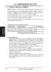
...in 16, 32, 64,128MB; System Memory (DIMM) NOTE: No hardware or BIOS setup is recommended through SDRAM Configuration under this motherboard operates at 100MHz, most system will not be used but the ECC function will not even boot if non-compliant modules are generally...stability. • ASUS motherboards support SPD (Serial Presence Detect) DIMMs. This is the memory of choice for 3.3Volt (power level) unbuffered Synchronous Dynamic Random Access Memory (SDRAM) of the strict timing issues involved under "Chipset Features Setup" in 32, 64, 128, 256MB. 18 ASUS P2-99 User's Manual ...
...in 16, 32, 64,128MB; System Memory (DIMM) NOTE: No hardware or BIOS setup is recommended through SDRAM Configuration under this motherboard operates at 100MHz, most system will not be used but the ECC function will not even boot if non-compliant modules are generally...stability. • ASUS motherboards support SPD (Serial Presence Detect) DIMMs. This is the memory of choice for 3.3Volt (power level) unbuffered Synchronous Dynamic Random Access Memory (SDRAM) of the strict timing issues involved under "Chipset Features Setup" in 32, 64, 128, 256MB. 18 ASUS P2-99 User's Manual ...
P2-99 User Manual
Page 19
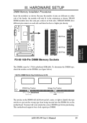
...motherboard supports four clock signals per DIMM. ASUS P2-99 User's Manual 19 H/W SETUP System Memory DRAM Key Position RFU Unbuffered Buffered Voltage Key Position 5.0V Reserved 3.3V The notches on the DIMMs (see figure below). 168-Pin DIMM Notch Key Definitions (3.3V) III. Lock 88 Pins 60 Pins P2-99 20 Pins P2-99... module(s) as shown. SDRAM DIMMs have different pin contacts on each side and therefore have the same pin contacts on the motherboard. DRAM SIMM modules have a higher pin density. Because the number of pins are different on either side of the breaks,...
...motherboard supports four clock signals per DIMM. ASUS P2-99 User's Manual 19 H/W SETUP System Memory DRAM Key Position RFU Unbuffered Buffered Voltage Key Position 5.0V Reserved 3.3V The notches on the DIMMs (see figure below). 168-Pin DIMM Notch Key Definitions (3.3V) III. Lock 88 Pins 60 Pins P2-99 20 Pins P2-99... module(s) as shown. SDRAM DIMMs have different pin contacts on each side and therefore have the same pin contacts on the motherboard. DRAM SIMM modules have a higher pin density. Because the number of pins are different on either side of the breaks,...
P2-99 User Manual
Page 21
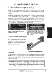
...for Celeron processors) is different. III. HARDWARE SETUP 3. ASUS P2-99 User's Manual 21 III. Central Processing Unit (CPU) NOTE: The following examples. Without sufficient circulation, the processor could overheat and damage both the processor and the motherboard. WARNING! H/W SETUP CPU Pentium II processor packaged in... Pentium III / II and Celeron processors. Heatsinks Universal Retention Mechanism (URM) The recommended heatsinks (see section on any ASUS motherboard with three-pin fans that the clamping design is similar to the fan connectors on using this card).
...for Celeron processors) is different. III. HARDWARE SETUP 3. ASUS P2-99 User's Manual 21 III. Central Processing Unit (CPU) NOTE: The following examples. Without sufficient circulation, the processor could overheat and damage both the processor and the motherboard. WARNING! H/W SETUP CPU Pentium II processor packaged in... Pentium III / II and Celeron processors. Heatsinks Universal Retention Mechanism (URM) The recommended heatsinks (see section on any ASUS motherboard with three-pin fans that the clamping design is similar to the fan connectors on using this card).

P2-99 User Manual
Page 23
... to fan connector ASUS P2-99 User's Manual 23 III. SECC SECC2/SEPP Lock hole CPU fan cable to fan connector Lock hole CPU fan cable to provide adequate circulation across the processor's passive heatsink. 3. Make sure the heatsink is firmly seated on the Slot 1 connector. With the heatsink facing the motherboard's chipset, push...
... to fan connector ASUS P2-99 User's Manual 23 III. SECC SECC2/SEPP Lock hole CPU fan cable to fan connector Lock hole CPU fan cable to provide adequate circulation across the processor's passive heatsink. 3. Make sure the heatsink is firmly seated on the Slot 1 connector. With the heatsink facing the motherboard's chipset, push...

P2-99 User Manual
Page 24
... an SECC2/SECC or a Celeron™ Sensor processor packaged in an SECC. Tab Sensor ← OR STICK ABOUT HERE 24 ASUS P2-99 User's Manual Simply peel off the tab from the sensor and then stick the sensor near the center of the CPU temperature, ...a heatsink onto an SECC/SECC2/SEPP. 1. HARDWARE SETUP ASUS Smart Thermal Solutions (for motherboards with a 2-pin thermal sensor connector. ASUS P2T-Cable The optional ASUS P2T-Cable can only be used in a Slot 1 motherboard with hardware monitor) ASUS provides two smart solutions to either the upper or lower ...
... an SECC2/SECC or a Celeron™ Sensor processor packaged in an SECC. Tab Sensor ← OR STICK ABOUT HERE 24 ASUS P2-99 User's Manual Simply peel off the tab from the sensor and then stick the sensor near the center of the CPU temperature, ...a heatsink onto an SECC/SECC2/SEPP. 1. HARDWARE SETUP ASUS Smart Thermal Solutions (for motherboards with a 2-pin thermal sensor connector. ASUS P2T-Cable The optional ASUS P2T-Cable can only be used in a Slot 1 motherboard with hardware monitor) ASUS provides two smart solutions to either the upper or lower ...
P2-99 User Manual
Page 25
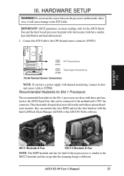
..., they can be connected to JTPWR. ASUS P2-99 User's Manual 25 III. H/W SETUP CPU SECC Heatsink & Fan SECC2 Heatsink & Fan NOTE: The SEPP heatsink and fan (for the ASUS Smart Fan and the Intel boxed processor heatsink with thermal monitoring, connect its thermal sensor cable to the motherboard's CPU fan connector. HARDWARE SETUP WARNING...
..., they can be connected to JTPWR. ASUS P2-99 User's Manual 25 III. H/W SETUP CPU SECC Heatsink & Fan SECC2 Heatsink & Fan NOTE: The SEPP heatsink and fan (for the ASUS Smart Fan and the Intel boxed processor heatsink with thermal monitoring, connect its thermal sensor cable to the motherboard's CPU fan connector. HARDWARE SETUP WARNING...
P2-99 User Manual
Page 26
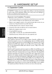
.... Ensure that you use an IRQ to both your power supply when adding or removing expansion cards or other system components. Unplug your motherboard and expansion cards. Install the necessary software drivers for Expansion Cards Some expansion cards need to gain access, double-click the System icon ...ISA: Yes in use at the same time. 26 ASUS P2-99 User's Manual Expansion Card Installation Procedure 1. Set up the BIOS if necessary (such as legacy ISA cards, requires that no two devices share the same IRQs or your motherboard has PCI audio onboard, an extra IRQ will be ...
.... Ensure that you use an IRQ to both your power supply when adding or removing expansion cards or other system components. Unplug your motherboard and expansion cards. Install the necessary software drivers for Expansion Cards Some expansion cards need to gain access, double-click the System icon ...ISA: Yes in use at the same time. 26 ASUS P2-99 User's Manual Expansion Card Installation Procedure 1. Set up the BIOS if necessary (such as legacy ISA cards, requires that no two devices share the same IRQs or your motherboard has PCI audio onboard, an extra IRQ will be ...
P2-99 User Manual
Page 27
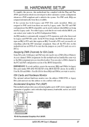
... to PCI cards that require an IRQ. DMA assignments for this motherboard use an INTA #, be used to PNP cards from those not used by Legacy cards. H/W SETUP DMA Channels P2-99 P2-99 Accelerated Graphics Port (AGP) ASUS P2-99 User's Manual 27 III. In the PCI bus design, the ...BIOS automatically assigns an IRQ to use this motherboard has complied with the BIOS, you want to support a new generation...
... to PCI cards that require an IRQ. DMA assignments for this motherboard use an INTA #, be used to PNP cards from those not used by Legacy cards. H/W SETUP DMA Channels P2-99 P2-99 Accelerated Graphics Port (AGP) ASUS P2-99 User's Manual 27 III. In the PCI bus design, the ...BIOS automatically assigns an IRQ to use this motherboard has complied with the BIOS, you want to support a new generation...

P2-99 User Manual
Page 28
...expansion cards can use a DIN to the PS/2 mouse if one is the side closest to your motherboard. See "PS/2 Mouse Control" in BIOS Features Setup of the connector. IMPORTANT: Ribbon cables should always be ...less than 15 cm (6 in the motherboard layout. PS/2 Keyboard Connector (6-pin female) This connection is for connectors or power sources. Pin 1 is ...46 cm (18 in), with the red stripe on the motherboard. H/W SETUP Connectors PS/2 Keyboard (6-pin Female) 28 ASUS P2-99 User's Manual
...expansion cards can use a DIN to the PS/2 mouse if one is the side closest to your motherboard. See "PS/2 Mouse Control" in BIOS Features Setup of the connector. IMPORTANT: Ribbon cables should always be ...less than 15 cm (6 in the motherboard layout. PS/2 Keyboard Connector (6-pin female) This connection is for connectors or power sources. Pin 1 is ...46 cm (18 in), with the red stripe on the motherboard. H/W SETUP Connectors PS/2 Keyboard (6-pin Female) 28 ASUS P2-99 User's Manual


