
User Manual
Page 1
P/I-P55TP4N Motherboard USER'S MANUAL
P/I-P55TP4N Motherboard USER'S MANUAL
User Manual
Page 2
...displayed on the motherboard itself. All rights reserved. Product names appearing in this manual may or may not be registered trademarks or copyrights of merchantability or fitness for indirect, special, incidental, or consequential damages of any kind, even if ASUS has been advised ... number are mentioned for backup purposes. Product Name: Product Revision: Manual Revision: BIOS Version: Release Date: P/I-P55TP4N 1.01 2.0 #401A0-0201 or later May 1996 II P/I-P55TP4N User's Manual USER'S NOTICE No part of this product, including the product and software may be reproduced, transmitted...
...displayed on the motherboard itself. All rights reserved. Product names appearing in this manual may or may not be registered trademarks or copyrights of merchantability or fitness for indirect, special, incidental, or consequential damages of any kind, even if ASUS has been advised ... number are mentioned for backup purposes. Product Name: Product Revision: Manual Revision: BIOS Version: Release Date: P/I-P55TP4N 1.01 2.0 #401A0-0201 or later May 1996 II P/I-P55TP4N User's Manual USER'S NOTICE No part of this product, including the product and software may be reproduced, transmitted...
User Manual
Page 4
... Installation Procedures 13 Level 2 External Static RAM (SRAM) Cache 14 Compatible Cache Modules for ISA Cards 17 ASUS MediaBus Card 18 5. Expansion Cards 16 Expansion Card Installation Procedure 16 Assigning IRQs for Expansion Cards 16 Assigning DMA...1 Item Checklist 1 II. FEATURES 2 Features of This Motherboard 2 Parts of the Motherboard 4 Jumpers 5 Expansion Slots 5 Connectors 5 Installation Steps 6 1. Central Processing Unit (CPU 15 4. INSTALLATION 4 Map of the Motherboard 3 III. INTRODUCTION 1 How this Motherboard 14 3. CONTENTS I -P55TP4N User's Manual
... Installation Procedures 13 Level 2 External Static RAM (SRAM) Cache 14 Compatible Cache Modules for ISA Cards 17 ASUS MediaBus Card 18 5. Expansion Cards 16 Expansion Card Installation Procedure 16 Assigning IRQs for Expansion Cards 16 Assigning DMA...1 Item Checklist 1 II. FEATURES 2 Features of This Motherboard 2 Parts of the Motherboard 4 Jumpers 5 Expansion Slots 5 Connectors 5 Installation Steps 6 1. Central Processing Unit (CPU 15 4. INSTALLATION 4 Map of the Motherboard 3 III. INTRODUCTION 1 How this Motherboard 14 3. CONTENTS I -P55TP4N User's Manual
User Manual
Page 7
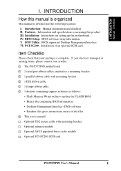
...and specifications concerning this manual is organized This manual is complete. Item Checklist Please check that your retailer. √ The P/I -P55TP4N User's Manual 1 INTRODUCTION (Manual / Checklist) I . DMI Utility: BIOS supported Desktop Management Interface VI. PCI-SC200: Installation of...files √ This user's manual Optional PS/2 mouse cable with mounting bracket Optional infrared module Optional ASUS pipelined burst cache module Optional PCI-SC200 SCSI card P/I -P55TP4N motherboard √ 2 serial port ribbon cables attached to a mounting bracket √ 1 parallel ribbon ...
...and specifications concerning this manual is organized This manual is complete. Item Checklist Please check that your retailer. √ The P/I -P55TP4N User's Manual 1 INTRODUCTION (Manual / Checklist) I . DMI Utility: BIOS supported Desktop Management Interface VI. PCI-SC200: Installation of...files √ This user's manual Optional PS/2 mouse cable with mounting bracket Optional infrared module Optional ASUS pipelined burst cache module Optional PCI-SC200 SCSI card P/I -P55TP4N motherboard √ 2 serial port ribbon cables attached to a mounting bracket √ 1 parallel ribbon ...
User Manual
Page 8
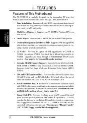
Two floppy drives of either an standard PCI card or the ASUS MediaBus Card. • ASUS MediaBus Rev 2.0: Features an expansion slot extension shared with PCI Slot 4 for the demanding PC user who wants a great many features in one easy-to-... and PCI Expansion Slots: Provides three 16-bit ISA slots, three 32-bit PCI slots, and one PCI/MediaBus 2.0 which allows the use of This Motherboard The P/I -P55TP4N User's Manual UART2 can also be directed to 512KB. Upgrades are also supported without an external card. II. FEATURES (Features) II.
Two floppy drives of either an standard PCI card or the ASUS MediaBus Card. • ASUS MediaBus Rev 2.0: Features an expansion slot extension shared with PCI Slot 4 for the demanding PC user who wants a great many features in one easy-to-... and PCI Expansion Slots: Provides three 16-bit ISA slots, three 32-bit PCI slots, and one PCI/MediaBus 2.0 which allows the use of This Motherboard The P/I -P55TP4N User's Manual UART2 can also be directed to 512KB. Upgrades are also supported without an external card. II. FEATURES (Features) II.
User Manual
Page 9
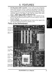
...PCI 4 or ASUS MediaBus 2.0 72-pin SIMM Sockets Intel's 430FX PCIset CPU ZIF Socket 7 L2 Upgrade Cache Expansion Slot Onboard 256KB/ 512KB Pipelined Burst L2 Cache P/I /O II. II. BIOS supports IDE CD-ROM boot-up. • Optional IrDA and PS/2 Mouse Connector: This motherboard supports an ...data transfer rates, and supports Enhanced IDE devices such as Tape Backup and CD-ROM drives. FEATURES (Parts of the Motherboard 3 ISA Slots Flash ROM 3 PCI Slots Super Multi-I -P55TP4N User's Manual 3 This controller supports PIO Modes 3 and 4 and Bus Master IDE DMA Mode 2. FEATURES •...
...PCI 4 or ASUS MediaBus 2.0 72-pin SIMM Sockets Intel's 430FX PCIset CPU ZIF Socket 7 L2 Upgrade Cache Expansion Slot Onboard 256KB/ 512KB Pipelined Burst L2 Cache P/I /O II. II. BIOS supports IDE CD-ROM boot-up. • Optional IrDA and PS/2 Mouse Connector: This motherboard supports an ...data transfer rates, and supports Enhanced IDE devices such as Tape Backup and CD-ROM drives. FEATURES (Parts of the Motherboard 3 ISA Slots Flash ROM 3 PCI Slots Super Multi-I -P55TP4N User's Manual 3 This controller supports PIO Modes 3 and 4 and Bus Master IDE DMA Mode 2. FEATURES •...
User Manual
Page 10
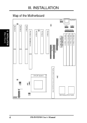
III. INSTALLATION (Map of the Motherboard JP7 JP4 JP5 PS/2 Mouse Keyboard COM 1 COM 2 Parallel Printer SIMM Slot 4 (Bank 1) SIMM Slot 3 (Bank 1) SIMM Slot 2 (Bank 0) SIMM Slot 1 (Bank 0) Board Power Input ... L2 Cache Pipelined Burst Level 2 Cache Expansion Slot CPU ZIF Socket 8 JP14 JP30 JP15 JP22 JP23 JP24 JP26 JP27 JP28 Case Conn (CON 1) Infrared JP31 4 P/I-P55TP4N User's Manual
III. INSTALLATION (Map of the Motherboard JP7 JP4 JP5 PS/2 Mouse Keyboard COM 1 COM 2 Parallel Printer SIMM Slot 4 (Bank 1) SIMM Slot 3 (Bank 1) SIMM Slot 2 (Bank 0) SIMM Slot 1 (Bank 0) Board Power Input ... L2 Cache Pipelined Burst Level 2 Cache Expansion Slot CPU ZIF Socket 8 JP14 JP30 JP15 JP22 JP23 JP24 JP26 JP27 JP28 Case Conn (CON 1) Infrared JP31 4 P/I-P55TP4N User's Manual
User Manual
Page 11
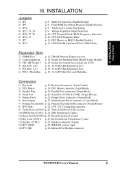
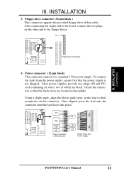
... (26-pin Block) 4) Serial Port p. 20 Serial Port COM1 & COM2 (10-pin Blocks) 5) Floppy Drive p. 21 Floppy Drive connector (34-pin Block) 6) Power Input p. 21 Motherboard Power connector (12-pin Block) 7) Primary/Second IDE p. 22 Primary/Secondary IDE connector (40-pin Blocks) 8) JP30 (Fan) p. 22 CPU 12V Cooling Fan connector 9) Turbo... lead (5-pins) 13) Speaker (CON1) p. 23 Speaker connector (4-pins) 14) JP17 (LED) p. 24 IDE LED activity light 16) JP31 (IR) p. 24 Infrared Port Module connector P/I-P55TP4N User's Manual 5 INSTALLATION (Map of Board) III. III.
... (26-pin Block) 4) Serial Port p. 20 Serial Port COM1 & COM2 (10-pin Blocks) 5) Floppy Drive p. 21 Floppy Drive connector (34-pin Block) 6) Power Input p. 21 Motherboard Power connector (12-pin Block) 7) Primary/Second IDE p. 22 Primary/Secondary IDE connector (40-pin Blocks) 8) JP30 (Fan) p. 22 CPU 12V Cooling Fan connector 9) Turbo... lead (5-pins) 13) Speaker (CON1) p. 23 Speaker connector (4-pins) 14) JP17 (LED) p. 24 IDE LED activity light 16) JP31 (IR) p. 24 Infrared Port Module connector P/I-P55TP4N User's Manual 5 INSTALLATION (Map of Board) III. III.
User Manual
Page 12
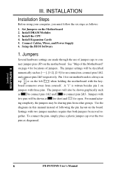
... shown as diagramed. III. Install DRAM Modules 3. Jumpers Several hardware settings are made through the use of following the pin layout on the motherboard. For manufactur- INSTALLATION (Jumpers) 6 P/I-P55TP4N User's Manual Connect Cables, Wires, and Power Supply 6. Install the CPU 4. See "Map of jumpers. A "1" is always on Pin 1 Pin 1 top or on...
... shown as diagramed. III. Install DRAM Modules 3. Jumpers Several hardware settings are made through the use of following the pin layout on the motherboard. For manufactur- INSTALLATION (Jumpers) 6 P/I-P55TP4N User's Manual Connect Cables, Wires, and Power Supply 6. Install the CPU 4. See "Map of jumpers. A "1" is always on Pin 1 Pin 1 top or on...

User Manual
Page 13
... are used for connectors or power sources. Hold components by the edges and try not to your computer. 1. INSTALLATION (Jumpers) P/I-P55TP4N User's Manual 7 Placing jumper caps over these will cause damage to touch the IC chips. 3. Unplug your computer when working on...computer components. 4. Place components on a grounded antistatic pad or on the bag that came with the component whenever you work on your motherboard. III. INSTALLATION WARNING: Some pins are clearly separated from static electricity, you should follow some precautions whenever you work on lay down ...
... are used for connectors or power sources. Hold components by the edges and try not to your computer. 1. INSTALLATION (Jumpers) P/I-P55TP4N User's Manual 7 Placing jumper caps over these will cause damage to touch the IC chips. 3. Unplug your computer when working on...computer components. 4. Place components on a grounded antistatic pad or on the bag that came with the component whenever you work on your motherboard. III. INSTALLATION WARNING: Some pins are clearly separated from static electricity, you should follow some precautions whenever you work on lay down ...

User Manual
Page 15
...STD 3.3V - 3.465V (Default) VRE 3.4V - 3.6V Voltage Regulator Output Selection (STD / VRE) P/I-P55TP4N User's Manual 9 If you have either 256KB or 512KB. IMPORTANT: See page 14 "SRAM Cache" for locations... install a cache module of your cache combination, set the voltage supplied to 512KB. An "ASUS" or "COAST" cache module can be used to upgrade the 256KB version to the CPU...JP22, 23, 24) These jumpers set the following jumpers according to the total amount of Motherboard" for installation procedures. III. If there is present onboard and installed as a module. ...
...STD 3.3V - 3.465V (Default) VRE 3.4V - 3.6V Voltage Regulator Output Selection (STD / VRE) P/I-P55TP4N User's Manual 9 If you have either 256KB or 512KB. IMPORTANT: See page 14 "SRAM Cache" for locations... install a cache module of your cache combination, set the voltage supplied to 512KB. An "ASUS" or "COAST" cache module can be used to upgrade the 256KB version to the CPU...JP22, 23, 24) These jumpers set the following jumpers according to the total amount of Motherboard" for installation procedures. III. If there is present onboard and installed as a module. ...
User Manual
Page 18
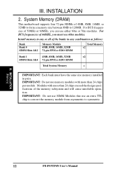
... in any or all of 66MHz, you can use 60ns modules. Modules with more than 24 chips per module. INSTALLATION (Memory) 12 P/I-P55TP4N User's Manual System Memory (DRAM) This motherboard supports four 72-pin SIMMs of the memory subsystem and will cause unreliable operation. IMPORTANT: Do not use an extra TTL chip...
... in any or all of 66MHz, you can use 60ns modules. Modules with more than 24 chips per module. INSTALLATION (Memory) 12 P/I-P55TP4N User's Manual System Memory (DRAM) This motherboard supports four 72-pin SIMMs of the memory subsystem and will cause unreliable operation. IMPORTANT: Do not use an extra TTL chip...
User Manual
Page 20
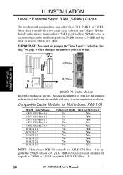
III. A cache module can use all modules for upgrade to 256KB or 512KB except the ASUS CM1 Rev. 1.6. 14 P/I-P55TP4N User's Manual INSTALLATION (SRAM Cache) 38 Pins 256KB PB Cache Module Insert the module as shown. Most likely you will have two cache ... 256KB or 512KB. IMPORTANT: You must set jumper 16 "Total Level 2 Cache Size Setting" on either side of Motherboard" for Motherboard PCB 1.01 SIMM Cache Module ASUS CM1 Rev 1.0 ASUS CM1 Rev 1.3 ASUS CM4 Rev 1.5 ASUS CM1 Rev 1.6 ASUS CM1 Rev 3.0 COAST 1.1 COAST 1.2 COAST 1.3 COAST 2.0 COAST 2.1 COAST 3.0 256KB to 512KB No No No Yes Yes...
III. A cache module can use all modules for upgrade to 256KB or 512KB except the ASUS CM1 Rev. 1.6. 14 P/I-P55TP4N User's Manual INSTALLATION (SRAM Cache) 38 Pins 256KB PB Cache Module Insert the module as shown. Most likely you will have two cache ... 256KB or 512KB. IMPORTANT: You must set jumper 16 "Total Level 2 Cache Size Setting" on either side of Motherboard" for Motherboard PCB 1.01 SIMM Cache Module ASUS CM1 Rev 1.0 ASUS CM1 Rev 1.3 ASUS CM4 Rev 1.5 ASUS CM1 Rev 1.6 ASUS CM1 Rev 3.0 COAST 1.1 COAST 1.2 COAST 1.3 COAST 2.0 COAST 2.1 COAST 3.0 256KB to 512KB No No No Yes Yes...

User Manual
Page 21
...first turn on the fan and close the socket's lever. IMPORTANT: You must set jumpers for "BUS Frequency Selection" on page 10 depending on the motherboard next to a 90-degree right angle. WARNING: Without a fan, the CPU can overheat and cause damage to BUS Frequency Ratio" and jumpers for "...22 "CPU Cooling Fan Connector). Locate the ZIF socket and open it to insert the CPU. Insert the CPU with Pentium Processor White Dot P/I-P55TP4N User's Manual 15 Notice that you should point towards the end the of the CPU. Once completely inserted, hold down on your guide. ...
...first turn on the fan and close the socket's lever. IMPORTANT: You must set jumpers for "BUS Frequency Selection" on page 10 depending on the motherboard next to a 90-degree right angle. WARNING: Without a fan, the CPU can overheat and cause damage to BUS Frequency Ratio" and jumpers for "...22 "CPU Cooling Fan Connector). Locate the ZIF socket and open it to insert the CPU. Insert the CPU with Pentium Processor White Dot P/I-P55TP4N User's Manual 15 Notice that you should point towards the end the of the CPU. Once completely inserted, hold down on your guide. ...
User Manual
Page 22
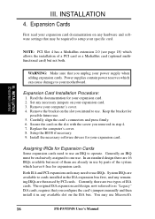
...when adding expansion cards. NOTE: PCI Slot 4 has a MediaBus extension 2.0 (see page 18) which can cause damage to use Microsoft's 16 P/I-P55TP4N User's Manual Power supplies contain power reserves which allows the installation of a PCI card or a MediaBus card (optional multifunctional card) but most of... ISA cards. Remove your expansion card. 3. System IRQs are then used by parts of the system which leaves 6 free for your motherboard. You may need to your expansion card. 2. Read the documentation for expansion cards. Setup the BIOS if necessary. 9. Both ISA and PCI...
...when adding expansion cards. NOTE: PCI Slot 4 has a MediaBus extension 2.0 (see page 18) which can cause damage to use Microsoft's 16 P/I-P55TP4N User's Manual Power supplies contain power reserves which allows the installation of a PCI card or a MediaBus card (optional multifunctional card) but most of... ISA cards. Remove your expansion card. 3. System IRQs are then used by parts of the system which leaves 6 free for your motherboard. You may need to your expansion card. 2. Read the documentation for expansion cards. Setup the BIOS if necessary. 9. Both ISA and PCI...
User Manual
Page 23
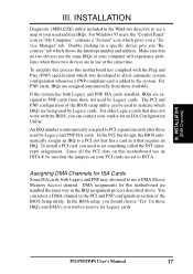
... bus design, the BIOS automatically assigns an IRQ to PCI expansion cards after those used by Legacy cards. To simplify this process this motherboard use at the same time. The PCI and PNP configuration of the BIOS Setup utility. Assigning DMA Channels for Legacy cards. III.... cards installed, IRQs are assigned to the system. INSTALLATION (DMA Channels) III. To install a PCI card, you a "Device Manager" tab. P/I-P55TP4N User's Manual 17 DMA assignments for an ISA Configuration Utility. For Windows 95 users, the "Control Panel" icon in the PCI and PNP configuration section...
... bus design, the BIOS automatically assigns an IRQ to PCI expansion cards after those used by Legacy cards. To simplify this process this motherboard use at the same time. The PCI and PNP configuration of the BIOS Setup utility. Assigning DMA Channels for Legacy cards. III.... cards installed, IRQs are assigned to the system. INSTALLATION (DMA Channels) III. To install a PCI card, you a "Device Manager" tab. P/I-P55TP4N User's Manual 17 DMA assignments for an ISA Configuration Utility. For Windows 95 users, the "Control Panel" icon in the PCI and PNP configuration section...
User Manual
Page 24
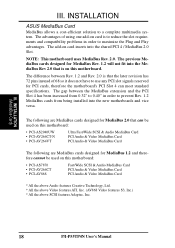
... system. The following are MediaBus cards designed for MediaBus 2.0 that the later revision has 72 pins instead of using one add-on this motherboard: • PCI-AS7870 • PCI-AV264CT • PCI-AV868 Fast/Wide SCSI & Audio MediaBus Card PCI Audio & Video MediaBus ...* All the above Video features ATI, Inc. (AV868 Video features S3, Inc.) * All the above SCSI features Adaptec, Inc. 18 P/I-P55TP4N User's Manual INSTALLATION ASUS MediaBus Card MediaBus allows a cost-efficient solution to prevent Rev. 1.2 MediaBus cards from being installed into the shared PCI 4 / MediaBus 2.0...
... system. The following are MediaBus cards designed for MediaBus 2.0 that the later revision has 72 pins instead of using one add-on this motherboard: • PCI-AS7870 • PCI-AV264CT • PCI-AV868 Fast/Wide SCSI & Audio MediaBus Card PCI Audio & Video MediaBus ...* All the above Video features ATI, Inc. (AV868 Video features S3, Inc.) * All the above SCSI features Adaptec, Inc. 18 P/I-P55TP4N User's Manual INSTALLATION ASUS MediaBus Card MediaBus allows a cost-efficient solution to prevent Rev. 1.2 MediaBus cards from being installed into the shared PCI 4 / MediaBus 2.0...

User Manual
Page 25
... hard drives and floppy drives. You must purchase an optional PS/2 mouse set "PS/2 Mouse Selection" on page 11 to the power connector on the motherboard. Pin 1 is for a standard IBM-compatible keyboard. IDE ribbon cable must be less than 6in. (15cm) from Keyboard 2. III. INSTALLATION (Connectors) Keyboard Connector (5-pin female...) This connection is the side closest to enable the PS/2 Mouse. 1 234 58 1 234 58 1: GND 2: DATA 3: NC 4: VCC 5: CLK 8: NC PS/2 Mouse Module Connector P/I-P55TP4N User's Manual 19
... hard drives and floppy drives. You must purchase an optional PS/2 mouse set "PS/2 Mouse Selection" on page 11 to the power connector on the motherboard. Pin 1 is for a standard IBM-compatible keyboard. IDE ribbon cable must be less than 6in. (15cm) from Keyboard 2. III. INSTALLATION (Connectors) Keyboard Connector (5-pin female...) This connection is the side closest to enable the PS/2 Mouse. 1 234 58 1 234 58 1: GND 2: DATA 3: NC 4: VCC 5: CLK 8: NC PS/2 Mouse Module Connector P/I-P55TP4N User's Manual 19
User Manual
Page 27
... 5 Volt power supply. III. Once aligned, press the lead onto the connector until the lead locks into place. +5V GND +12V PG Power Connector on Motherboard P9 -5V -12V +5V RED RED RED WHT BLK BLK BLK BLK BLU YLW RED ORG P8 Power Plugs from the power supply, ensure first... that the black wires are black. To connect the leads from Power Supply P/I-P55TP4N User's Manual 21 Most power supplies provide two plugs (P8 and P9), each containing six wires, two of which are located in the middle. Power...
... 5 Volt power supply. III. Once aligned, press the lead onto the connector until the lead locks into place. +5V GND +12V PG Power Connector on Motherboard P9 -5V -12V +5V RED RED RED WHT BLK BLK BLK BLK BLU YLW RED ORG P8 Power Plugs from the power supply, ensure first... that the black wires are black. To connect the leads from Power Supply P/I-P55TP4N User's Manual 21 Most power supplies provide two plugs (P8 and P9), each containing six wires, two of which are located in the middle. Power...

User Manual
Page 28
...settings. III. Depending on the secondary IDE connector. Pin 1 III. Air Flow JP30 +12V GND CPU Fan Power Air Flow 22 P/I-P55TP4N User's Manual Primary / Secondary IDE connectors (Two 40-pin Block) This connector supports the provided IDE hard disk ribbon cable. After connecting... polarity of 500mAMP (6WATT) or less. WARNING: Damage may occur to the documentation of the expansion slots. Please refer to the motherboard and/or the CPU fan if these pins are incorrectly used. INSTALLATION (Connectors) Secondary IDE Connector Primary IDE Connector 8. Connect the fan...
...settings. III. Depending on the secondary IDE connector. Pin 1 III. Air Flow JP30 +12V GND CPU Fan Power Air Flow 22 P/I-P55TP4N User's Manual Primary / Secondary IDE connectors (Two 40-pin Block) This connector supports the provided IDE hard disk ribbon cable. After connecting... polarity of 500mAMP (6WATT) or less. WARNING: Damage may occur to the documentation of the expansion slots. Please refer to the motherboard and/or the CPU fan if these pins are incorrectly used. INSTALLATION (Connectors) Secondary IDE Connector Primary IDE Connector 8. Connect the fan...


