User Manual
Page 1
P/I-P55TP4N Motherboard USER'S MANUAL
P/I-P55TP4N Motherboard USER'S MANUAL
User Manual
Page 2
... the top-left of the screen during this manual may or may visit ASUSTeK's home page at: http://www.asus.com.tw/ Products mentioned in this manual release. Product Name: Product Revision: Manual Revision: BIOS Version: Release Date: P/I-P55TP4N 1.01 2.0 #401A0-0201 or later May 1996 II P/I-P55TP4N User's Manual Your BIOS version displayed on the motherboard...
... the top-left of the screen during this manual may or may visit ASUSTeK's home page at: http://www.asus.com.tw/ Products mentioned in this manual release. Product Name: Product Revision: Manual Revision: BIOS Version: Release Date: P/I-P55TP4N 1.01 2.0 #401A0-0201 or later May 1996 II P/I-P55TP4N User's Manual Your BIOS version displayed on the motherboard...
User Manual
Page 4
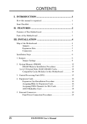
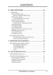
... Final Power Connection Procedures 25 IV P/I . Expansion Cards 16 Expansion Card Installation Procedure 16 Assigning IRQs for Expansion Cards 16 Assigning DMA Channels for this manual is organized 1 Item Checklist 1 II. Jumpers 6 Jumper Settings 8 2. FEATURES 2 Features of This Motherboard 2 Parts of the Motherboard 4 Jumpers 5 ...DRAM Memory Installation Procedures 13 Level 2 External Static RAM (SRAM) Cache 14 Compatible Cache Modules for ISA Cards 17 ASUS MediaBus Card 18 5. CONTENTS I -P55TP4N User's Manual INTRODUCTION 1 How this Motherboard 14 3.
... Final Power Connection Procedures 25 IV P/I . Expansion Cards 16 Expansion Card Installation Procedure 16 Assigning IRQs for Expansion Cards 16 Assigning DMA Channels for this manual is organized 1 Item Checklist 1 II. Jumpers 6 Jumper Settings 8 2. FEATURES 2 Features of This Motherboard 2 Parts of the Motherboard 4 Jumpers 5 ...DRAM Memory Installation Procedures 13 Level 2 External Static RAM (SRAM) Cache 14 Compatible Cache Modules for ISA Cards 17 ASUS MediaBus Card 18 5. CONTENTS I -P55TP4N User's Manual INTRODUCTION 1 How this Motherboard 14 3.
User Manual
Page 5
... The PCI-SC200 SCSI Interface Card 56 Setting Up the PCI-SC200 56 Setting the INT Assignment 57 Terminator Settings 57 SCSI ID Numbers 58 P/I-P55TP4N User's Manual V BIOS Setup 26 Standard CMOS Setup 27 Details of Standard CMOS Setup 28 BIOS Features Setup 31 Details of BIOS Features Setup 31 Chipset...
... The PCI-SC200 SCSI Interface Card 56 Setting Up the PCI-SC200 56 Setting the INT Assignment 57 Terminator Settings 57 SCSI ID Numbers 58 P/I-P55TP4N User's Manual V BIOS Setup 26 Standard CMOS Setup 27 Details of Standard CMOS Setup 28 BIOS Features Setup 31 Details of BIOS Features Setup 31 Chipset...

User Manual
Page 6
... radio communications. ference that interference will not occur in the Radio Interference Regulations of the Canadian Department of the FCC Rules. If this equipment. VI P/I-P55TP4N User's Manual
... radio communications. ference that interference will not occur in the Radio Interference Regulations of the Canadian Department of the FCC Rules. If this equipment. VI P/I-P55TP4N User's Manual
User Manual
Page 7
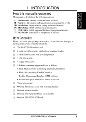
.... Item Checklist Please check that your retailer. √ The P/I-P55TP4N motherboard √ 2 serial port ribbon cables attached to a mounting bracket √ 1 parallel ribbon cable with mounting bracket Optional infrared module Optional ASUS pipelined burst cache module Optional PCI-SC200 SCSI card P/I . Introduction: Manual information and checklist II. INTRODUCTION How this product III. V. DMI...
.... Item Checklist Please check that your retailer. √ The P/I-P55TP4N motherboard √ 2 serial port ribbon cables attached to a mounting bracket √ 1 parallel ribbon cable with mounting bracket Optional infrared module Optional ASUS pipelined burst cache module Optional PCI-SC200 SCSI card P/I . Introduction: Manual information and checklist II. INTRODUCTION How this product III. V. DMI...
User Manual
Page 8
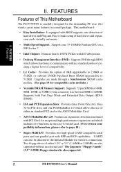
...standard protocol creating a higher level of compatibility. • L2 Cache: Provides the option of either an standard PCI card or the ASUS MediaBus Card. • ASUS MediaBus Rev 2.0: Features an expansion slot extension shared with I/O subsystems. • Desktop Management Interface (DMI): Supports DMI through BIOS which... BIOS supports auto detection of hard drives and Plug and Play to make setup of This Motherboard The P/I -P55TP4N User's Manual UART2 can also be directed to 128MB. This motherboard: • Easy Installation: Is equipped with EPP and ECP capabilities.
...standard protocol creating a higher level of compatibility. • L2 Cache: Provides the option of either an standard PCI card or the ASUS MediaBus Card. • ASUS MediaBus Rev 2.0: Features an expansion slot extension shared with I/O subsystems. • Desktop Management Interface (DMI): Supports DMI through BIOS which... BIOS supports auto detection of hard drives and Plug and Play to make setup of This Motherboard The P/I -P55TP4N User's Manual UART2 can also be directed to 128MB. This motherboard: • Easy Installation: Is equipped with EPP and ECP capabilities.
User Manual
Page 9
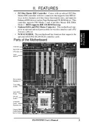
Parts of Board) PCI 4 or ASUS MediaBus 2.0 72-pin SIMM Sockets Intel's 430FX PCIset CPU ZIF Socket 7 L2 Upgrade Cache Expansion Slot Onboard 256KB/ 512KB Pipelined Burst L2 Cache P/I /O II. BIOS .... This controller supports PIO Modes 3 and 4 and Bus Master IDE DMA Mode 2. FEATURES (Parts of the Motherboard 3 ISA Slots Flash ROM 3 PCI Slots Super Multi-I -P55TP4N User's Manual 3 II. FEATURES • PCI Bus Master IDE Controller: Comes with an onboard PCI Bus Master IDE controller with two connectors that supports the optional...
Parts of Board) PCI 4 or ASUS MediaBus 2.0 72-pin SIMM Sockets Intel's 430FX PCIset CPU ZIF Socket 7 L2 Upgrade Cache Expansion Slot Onboard 256KB/ 512KB Pipelined Burst L2 Cache P/I /O II. BIOS .... This controller supports PIO Modes 3 and 4 and Bus Master IDE DMA Mode 2. FEATURES (Parts of the Motherboard 3 ISA Slots Flash ROM 3 PCI Slots Super Multi-I -P55TP4N User's Manual 3 II. FEATURES • PCI Bus Master IDE Controller: Comes with an onboard PCI Bus Master IDE controller with two connectors that supports the optional...
User Manual
Page 10
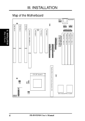
... L2 Cache Pipelined Burst Level 2 Cache Expansion Slot CPU ZIF Socket 8 JP14 JP30 JP15 JP22 JP23 JP24 JP26 JP27 JP28 Case Conn (CON 1) Infrared JP31 4 P/I-P55TP4N User's Manual INSTALLATION (Map of the Motherboard JP7 JP4 JP5 PS/2 Mouse Keyboard COM 1 COM 2 Parallel Printer SIMM Slot 4 (Bank 1) SIMM Slot 3 (Bank 1) SIMM Slot 2 (Bank...
... L2 Cache Pipelined Burst Level 2 Cache Expansion Slot CPU ZIF Socket 8 JP14 JP30 JP15 JP22 JP23 JP24 JP26 JP27 JP28 Case Conn (CON 1) Infrared JP31 4 P/I-P55TP4N User's Manual INSTALLATION (Map of the Motherboard JP7 JP4 JP5 PS/2 Mouse Keyboard COM 1 COM 2 Parallel Printer SIMM Slot 4 (Bank 1) SIMM Slot 3 (Bank 1) SIMM Slot 2 (Bank...
User Manual
Page 11
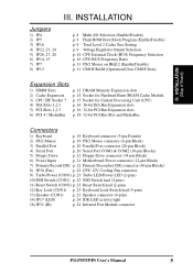
... lead (5-pins) 13) Speaker (CON1) p. 23 Speaker connector (4-pins) 14) JP17 (LED) p. 24 IDE LED activity light 16) JP31 (IR) p. 24 Infrared Port Module connector P/I-P55TP4N User's Manual 5
... lead (5-pins) 13) Speaker (CON1) p. 23 Speaker connector (4-pins) 14) JP17 (LED) p. 24 IDE LED activity light 16) JP31 (IR) p. 24 Infrared Port Module connector P/I-P55TP4N User's Manual 5
User Manual
Page 12
... with three pins. III. nect jumper pins (JP) on the board. The jumper settings will also be moved to con- Use the diagrams in this manual instead of jumper caps to - Install DRAM Modules 3. INSTALLATION (Jumpers) 6 P/I-P55TP4N User's Manual
... with three pins. III. nect jumper pins (JP) on the board. The jumper settings will also be moved to con- Use the diagrams in this manual instead of jumper caps to - Install DRAM Modules 3. INSTALLATION (Jumpers) 6 P/I-P55TP4N User's Manual

User Manual
Page 13
... against damage from jumpers in "Map of the Motherboard" on lay down components. III. Use a grounded wrist strap before handling computer components. 4. INSTALLATION (Jumpers) P/I-P55TP4N User's Manual 7 These are used for connectors or power sources. Placing jumper caps over these will cause damage to touch the IC chips. 3. Unplug your computer when...
... against damage from jumpers in "Map of the Motherboard" on lay down components. III. Use a grounded wrist strap before handling computer components. 4. INSTALLATION (Jumpers) P/I-P55TP4N User's Manual 7 These are used for connectors or power sources. Placing jumper caps over these will cause damage to touch the IC chips. 3. Unplug your computer when...
User Manual
Page 14
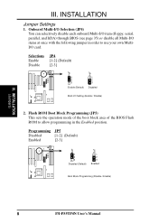
...) through BIOS (see page 35) or disable all Multi-I /O Setting (Enable / Disable) 2. Programming JP5 Disabled [1-2] (Default) Enabled [2-3] 1 2 3 Disabled (Default) 1 2 3 Enabled Boot Block Programming (Disable / Enable) 8 P/I-P55TP4N User's Manual INSTALLATION (Jumpers) III.
...) through BIOS (see page 35) or disable all Multi-I /O Setting (Enable / Disable) 2. Programming JP5 Disabled [1-2] (Default) Enabled [2-3] 1 2 3 Disabled (Default) 1 2 3 Enabled Boot Block Programming (Disable / Enable) 8 P/I-P55TP4N User's Manual INSTALLATION (Jumpers) III.

User Manual
Page 15
...(Jumpers) JP22 JP23 JP24 JP22 JP23 JP24 STD 3.3V - 3.465V (Default) VRE 3.4V - 3.6V Voltage Regulator Output Selection (STD / VRE) P/I-P55TP4N User's Manual 9 Total Level 2 Cache Size Setting (JP16) This jumper sets the total amount of L2 cache that is present onboard and installed as a module. Regardless...) 4. Selections JP24 JP23 JP22 STD 3.3V-3.465V [open] [open] [short] (Default) VRE 3.4V-3.6V [open] [short] [open] III. An "ASUS" or "COAST" cache module can be used to upgrade the 256KB version to the CPU. IMPORTANT: See page 14 "SRAM Cache" for locations), then you...
...(Jumpers) JP22 JP23 JP24 JP22 JP23 JP24 STD 3.3V - 3.465V (Default) VRE 3.4V - 3.6V Voltage Regulator Output Selection (STD / VRE) P/I-P55TP4N User's Manual 9 Total Level 2 Cache Size Setting (JP16) This jumper sets the total amount of L2 cache that is present onboard and installed as a module. Regardless...) 4. Selections JP24 JP23 JP22 STD 3.3V-3.465V [open] [open] [short] (Default) VRE 3.4V-3.6V [open] [short] [open] III. An "ASUS" or "COAST" cache module can be used to upgrade the 256KB version to the CPU. IMPORTANT: See page 14 "SRAM Cache" for locations), then you...

User Manual
Page 16
... 2.0x 66MHz [2-3] [1-2] [2-3] [open] [short] 2.0x 60MHz [1-2] [2-3] [2-3] [open] [short] 100MHz 90MHz 75MHz 1.5x 66MHz 1.5x 60MHz 1.5x 50MHz [2-3] [1-2] [2-3] [open] [open] [1-2] [2-3] [2-3] [open] [open] [2-3] [2-3] [1-2] [open] [open] 10 P/I-P55TP4N User's Manual These allow the selection of the CPU and the External frequency (called the BUS Clock) within the CPU. JP26 JP27 JP28 JP26 JP27 JP28 JP26...
... 2.0x 66MHz [2-3] [1-2] [2-3] [open] [short] 2.0x 60MHz [1-2] [2-3] [2-3] [open] [short] 100MHz 90MHz 75MHz 1.5x 66MHz 1.5x 60MHz 1.5x 50MHz [2-3] [1-2] [2-3] [open] [open] [1-2] [2-3] [2-3] [open] [open] [2-3] [2-3] [1-2] [open] [open] 10 P/I-P55TP4N User's Manual These allow the selection of the CPU and the External frequency (called the BUS Clock) within the CPU. JP26 JP27 JP28 JP26 JP27 JP28 JP26...
User Manual
Page 17
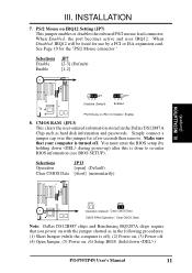
III. When Disabled, IRQ12 will be freed for use by holding down ) P/I-P55TP4N User's Manual 11 Selections JP7 Disable [2-3] (Default) Enable [1-2] JP7 123 Disabled (Default) JP7 123 Enabled PS/2 Mouse on IRQ12 Setting (JP7) This jumper enables or disables the ...
III. When Disabled, IRQ12 will be freed for use by holding down ) P/I-P55TP4N User's Manual 11 Selections JP7 Disable [2-3] (Default) Enable [1-2] JP7 123 Disabled (Default) JP7 123 Enabled PS/2 Mouse on IRQ12 Setting (JP7) This jumper enables or disables the ...
User Manual
Page 18
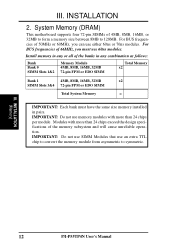
... unreliable operation. IMPORTANT: Do not use either 60ns or 70ns modules. III. INSTALLATION 2. Modules with more than 24 chips per module. INSTALLATION (Memory) 12 P/I-P55TP4N User's Manual For BUS frequencies of 66MHz, you can use memory modules with more than 24 chips exceed the design specifications of 4MB, 8MB, 16MB, or 32MB...
... unreliable operation. IMPORTANT: Do not use either 60ns or 70ns modules. III. INSTALLATION 2. Modules with more than 24 chips per module. INSTALLATION (Memory) 12 P/I-P55TP4N User's Manual For BUS frequencies of 66MHz, you can use memory modules with more than 24 chips exceed the design specifications of 4MB, 8MB, 16MB, or 32MB...

User Manual
Page 19
... the sides and the "Metal Clips" should snap on one end of the SIMM slots which requires the "Notched End" of the "Metal Clips". P/I-P55TP4N User's Manual 13 INSTALLATION DRAM Memory Installation Procedures: 1. To release the memory module, squeeze both "Metal Clips" outwards and rock the module out of the SIMM memory...
... the sides and the "Metal Clips" should snap on one end of the SIMM slots which requires the "Notched End" of the "Metal Clips". P/I-P55TP4N User's Manual 13 INSTALLATION DRAM Memory Installation Procedures: 1. To release the memory module, squeeze both "Metal Clips" outwards and rock the module out of the SIMM memory...
User Manual
Page 20
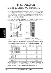
... of the break, the module will have 0KB, 256KB, or 512KB. Compatible Cache Modules for Motherboard PCB 1.01 SIMM Cache Module ASUS CM1 Rev 1.0 ASUS CM1 Rev 1.3 ASUS CM4 Rev 1.5 ASUS CM1 Rev 1.6 ASUS CM1 Rev 3.0 COAST 1.1 COAST 1.2 COAST 1.3 COAST 2.0 COAST 2.1 COAST 3.0 256KB to 512KB No No No Yes Yes Yes...Cache Module Insert the module as shown. Because the number of pins are made to 256KB or 512KB except the ASUS CM1 Rev. 1.6. 14 P/I-P55TP4N User's Manual A cache module can use ASUS CM1 Rev. 1.6 to upgrade the 256KB version to 512KB. 0KB version can be used to upgrade the 256KB ...
... of the break, the module will have 0KB, 256KB, or 512KB. Compatible Cache Modules for Motherboard PCB 1.01 SIMM Cache Module ASUS CM1 Rev 1.0 ASUS CM1 Rev 1.3 ASUS CM4 Rev 1.5 ASUS CM1 Rev 1.6 ASUS CM1 Rev 3.0 COAST 1.1 COAST 1.2 COAST 1.3 COAST 2.0 COAST 2.1 COAST 3.0 256KB to 512KB No No No Yes Yes Yes...Cache Module Insert the module as shown. Because the number of pins are made to 256KB or 512KB except the ASUS CM1 Rev. 1.6. 14 P/I-P55TP4N User's Manual A cache module can use ASUS CM1 Rev. 1.6 to upgrade the 256KB version to 512KB. 0KB version can be used to upgrade the 256KB ...

User Manual
Page 21
... thermal jelly to both the CPU and the motherboard. (See page 22 "CPU Cooling Fan Connector). Insert the CPU with Pentium Processor White Dot P/I-P55TP4N User's Manual 15 IMPORTANT: You must set jumpers for "BUS Frequency Selection" on page 10 depending on your system. Locate the ZIF socket and open it to...
... thermal jelly to both the CPU and the motherboard. (See page 22 "CPU Cooling Fan Connector). Insert the CPU with Pentium Processor White Dot P/I-P55TP4N User's Manual 15 IMPORTANT: You must set jumpers for "BUS Frequency Selection" on page 10 depending on your system. Locate the ZIF socket and open it to...


