
User Manual
Page 1
P/I-P55TP4N Motherboard USER'S MANUAL
P/I-P55TP4N Motherboard USER'S MANUAL
User Manual
Page 2
...copyrights of their respective companies. Product Name: Product Revision: Manual Revision: BIOS Version: Release Date: P/I-P55TP4N 1.01 2.0 #401A0-0201 or later May 1996 II P/I-P55TP4N User's Manual ASUS provides this manual "as is" without warranty of any kind, either express or implied, including but...time to the implied warranties or conditions of merchantability or fitness for a particular purpose. Your BIOS version displayed on the motherboard itself. ASUS may revise this manual from any defect or error in this manual or product. Product names appearing in this manual release...
...copyrights of their respective companies. Product Name: Product Revision: Manual Revision: BIOS Version: Release Date: P/I-P55TP4N 1.01 2.0 #401A0-0201 or later May 1996 II P/I-P55TP4N User's Manual ASUS provides this manual "as is" without warranty of any kind, either express or implied, including but...time to the implied warranties or conditions of merchantability or fitness for a particular purpose. Your BIOS version displayed on the motherboard itself. ASUS may revise this manual from any defect or error in this manual or product. Product names appearing in this manual release...
User Manual
Page 4
... Assigning DMA Channels for this manual is organized 1 Item Checklist 1 II. CONTENTS I -P55TP4N User's Manual Jumpers 6 Jumper Settings 8 2. INSTALLATION 4 Map of the Motherboard 3 III. System Memory (DRAM 12 DRAM Memory Installation Procedures 13 Level 2 External Static ...RAM (SRAM) Cache 14 Compatible Cache Modules for ISA Cards 17 ASUS MediaBus Card 18 5. External Connectors 19 Final Power Connection Procedures 25 IV P/I . FEATURES 2 Features of This Motherboard 2 Parts of the Motherboard 4 Jumpers 5 Expansion Slots 5 Connectors 5 Installation Steps 6 1. ...
... Assigning DMA Channels for this manual is organized 1 Item Checklist 1 II. CONTENTS I -P55TP4N User's Manual Jumpers 6 Jumper Settings 8 2. INSTALLATION 4 Map of the Motherboard 3 III. System Memory (DRAM 12 DRAM Memory Installation Procedures 13 Level 2 External Static ...RAM (SRAM) Cache 14 Compatible Cache Modules for ISA Cards 17 ASUS MediaBus Card 18 5. External Connectors 19 Final Power Connection Procedures 25 IV P/I . FEATURES 2 Features of This Motherboard 2 Parts of the Motherboard 4 Jumpers 5 Expansion Slots 5 Connectors 5 Installation Steps 6 1. ...
User Manual
Page 7
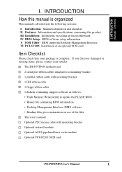
...information. Item Checklist Please check that your retailer. √ The P/I-P55TP4N motherboard √ 2 serial port ribbon cables attached to a mounting bracket √ 1 parallel ribbon cable with mounting bracket Optional infrared module Optional ASUS pipelined burst cache module Optional PCI-SC200 SCSI card P/I . IV....8226; Desktop Management Interface (DMI) software • Readme files gives instructions on setting up the motherboard. Features: Information and specifications concerning this manual is organized This manual is complete. DMI Utility: BIOS supported Desktop Management Interface...
...information. Item Checklist Please check that your retailer. √ The P/I-P55TP4N motherboard √ 2 serial port ribbon cables attached to a mounting bracket √ 1 parallel ribbon cable with mounting bracket Optional infrared module Optional ASUS pipelined burst cache module Optional PCI-SC200 SCSI card P/I . IV....8226; Desktop Management Interface (DMI) software • Readme files gives instructions on setting up the motherboard. Features: Information and specifications concerning this manual is organized This manual is complete. DMI Utility: BIOS supported Desktop Management Interface...
User Manual
Page 8
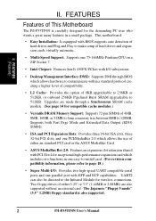
...slots, three 32-bit PCI slots, and one PCI/MediaBus 2.0 which allows the use of either an standard PCI card or the ASUS MediaBus Card. • ASUS MediaBus Rev 2.0: Features an expansion slot extension shared with PCI Slot 4 for the demanding PC user who wants a great many ...256KB Pipelined Burst SRAM upgradeable to the Infrared Module for compatible cache modules.) • Versatile DRAM Memory Support: Supports 72-pin SIMMs of This Motherboard The P/I -P55TP4N User's Manual UART2 can also be directed to 512KB. Two floppy drives of either 5.25" or 3.5" (1.44MB or 2.88MB) are made...
...slots, three 32-bit PCI slots, and one PCI/MediaBus 2.0 which allows the use of either an standard PCI card or the ASUS MediaBus Card. • ASUS MediaBus Rev 2.0: Features an expansion slot extension shared with PCI Slot 4 for the demanding PC user who wants a great many ...256KB Pipelined Burst SRAM upgradeable to the Infrared Module for compatible cache modules.) • Versatile DRAM Memory Support: Supports 72-pin SIMMs of This Motherboard The P/I -P55TP4N User's Manual UART2 can also be directed to 512KB. Two floppy drives of either 5.25" or 3.5" (1.44MB or 2.88MB) are made...
User Manual
Page 9
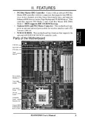
...transfer rates, and supports Enhanced IDE devices such as Tape Backup and CD-ROM drives. FEATURES (Parts of the Motherboard 3 ISA Slots Flash ROM 3 PCI Slots Super Multi-I -P55TP4N User's Manual 3 FEATURES • PCI Bus Master IDE Controller: Comes with an onboard PCI Bus Master IDE ...controller with two connectors that supports the optional ASUS PCI-SC200 SCSI controller cards. Parts of Board) PCI 4 or ASUS MediaBus 2.0 72-pin SIMM Sockets ...
...transfer rates, and supports Enhanced IDE devices such as Tape Backup and CD-ROM drives. FEATURES (Parts of the Motherboard 3 ISA Slots Flash ROM 3 PCI Slots Super Multi-I -P55TP4N User's Manual 3 FEATURES • PCI Bus Master IDE Controller: Comes with an onboard PCI Bus Master IDE ...controller with two connectors that supports the optional ASUS PCI-SC200 SCSI controller cards. Parts of Board) PCI 4 or ASUS MediaBus 2.0 72-pin SIMM Sockets ...
User Manual
Page 10
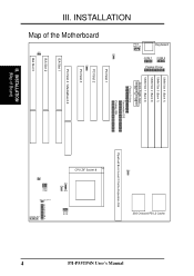
... Burst Level 2 Cache Expansion Slot CPU ZIF Socket 8 JP14 JP30 JP15 JP22 JP23 JP24 JP26 JP27 JP28 Case Conn (CON 1) Infrared JP31 4 P/I-P55TP4N User's Manual INSTALLATION (Map of the Motherboard JP7 JP4 JP5 PS/2 Mouse Keyboard COM 1 COM 2 Parallel Printer SIMM Slot 4 (Bank 1) SIMM Slot 3 (Bank 1) SIMM Slot 2 (Bank 0) SIMM Slot 1 (Bank...
... Burst Level 2 Cache Expansion Slot CPU ZIF Socket 8 JP14 JP30 JP15 JP22 JP23 JP24 JP26 JP27 JP28 Case Conn (CON 1) Infrared JP31 4 P/I-P55TP4N User's Manual INSTALLATION (Map of the Motherboard JP7 JP4 JP5 PS/2 Mouse Keyboard COM 1 COM 2 Parallel Printer SIMM Slot 4 (Bank 1) SIMM Slot 3 (Bank 1) SIMM Slot 2 (Bank 0) SIMM Slot 1 (Bank...
User Manual
Page 11
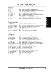
... (26-pin Block) 4) Serial Port p. 20 Serial Port COM1 & COM2 (10-pin Blocks) 5) Floppy Drive p. 21 Floppy Drive connector (34-pin Block) 6) Power Input p. 21 Motherboard Power connector (12-pin Block) 7) Primary/Second IDE p. 22 Primary/Secondary IDE connector (40-pin Blocks) 8) JP30 (Fan) p. 22 CPU 12V Cooling Fan connector 9) Turbo... lead (5-pins) 13) Speaker (CON1) p. 23 Speaker connector (4-pins) 14) JP17 (LED) p. 24 IDE LED activity light 16) JP31 (IR) p. 24 Infrared Port Module connector P/I-P55TP4N User's Manual 5 INSTALLATION (Map of Board) III. III.
... (26-pin Block) 4) Serial Port p. 20 Serial Port COM1 & COM2 (10-pin Blocks) 5) Floppy Drive p. 21 Floppy Drive connector (34-pin Block) 6) Power Input p. 21 Motherboard Power connector (12-pin Block) 7) Primary/Second IDE p. 22 Primary/Secondary IDE connector (40-pin Blocks) 8) JP30 (Fan) p. 22 CPU 12V Cooling Fan connector 9) Turbo... lead (5-pins) 13) Speaker (CON1) p. 23 Speaker connector (4-pins) 14) JP17 (LED) p. 24 IDE LED activity light 16) JP31 (IR) p. 24 Infrared Port Module connector P/I-P55TP4N User's Manual 5 INSTALLATION (Map of Board) III. III.
User Manual
Page 12
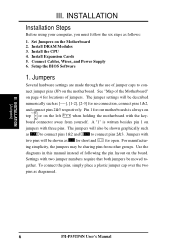
... with two jumper numbers require that both jumpers be sharing pins from yourself. INSTALLATION (Jumpers) 6 P/I-P55TP4N User's Manual Set Jumpers on the left when holding the motherboard with three pins. ing simplicity, the jumpers may be moved to con- III. Setup the BIOS ...no connection, connect pins 1&2, and connect pins 2&3 respectively. For manufactur- Jumpers Several hardware settings are made through the use of the Motherboard" on the board. III. Pin 1 for locations of jumpers. Use the diagrams in this manual instead of following the pin layout...
... with two jumper numbers require that both jumpers be sharing pins from yourself. INSTALLATION (Jumpers) 6 P/I-P55TP4N User's Manual Set Jumpers on the left when holding the motherboard with three pins. ing simplicity, the jumpers may be moved to con- III. Setup the BIOS ...no connection, connect pins 1&2, and connect pins 2&3 respectively. For manufactur- Jumpers Several hardware settings are made through the use of the Motherboard" on the board. III. Pin 1 for locations of jumpers. Use the diagrams in this manual instead of following the pin layout...

User Manual
Page 13
...try not to your computer when working on page 4. To protect the motherboard and other components against damage from jumpers in "Map of the Motherboard" on the inside. 2. Unplug your motherboard. Place components on a grounded antistatic pad or on the bag that ...came with the component whenever you work on your computer. 1. WARNING: Computer motheboards and components contain very delicate Integrated Circuit (IC) chips. III. INSTALLATION (Jumpers) P/I-P55TP4N User...
...try not to your computer when working on page 4. To protect the motherboard and other components against damage from jumpers in "Map of the Motherboard" on the inside. 2. Unplug your motherboard. Place components on a grounded antistatic pad or on the bag that ...came with the component whenever you work on your computer. 1. WARNING: Computer motheboards and components contain very delicate Integrated Circuit (IC) chips. III. INSTALLATION (Jumpers) P/I-P55TP4N User...

User Manual
Page 15
... JP22 STD 3.3V-3.465V [open] [open] [short] (Default) VRE 3.4V-3.6V [open] [short] [open] III. An "ASUS" or "COAST" cache module can be used to upgrade the 256KB version to the total amount of L2 cache that is present. If... there is no onboard cache, you must install a cache module of Motherboard" for installation procedures. Total Level 2 Cache Size Setting (JP16) This jumper sets the total amount of L2 ...JP24 STD 3.3V - 3.465V (Default) VRE 3.4V - 3.6V Voltage Regulator Output Selection (STD / VRE) P/I-P55TP4N User's Manual 9
... JP22 STD 3.3V-3.465V [open] [open] [short] (Default) VRE 3.4V-3.6V [open] [short] [open] III. An "ASUS" or "COAST" cache module can be used to upgrade the 256KB version to the total amount of L2 cache that is present. If... there is no onboard cache, you must install a cache module of Motherboard" for installation procedures. Total Level 2 Cache Size Setting (JP16) This jumper sets the total amount of L2 ...JP24 STD 3.3V - 3.465V (Default) VRE 3.4V - 3.6V Voltage Regulator Output Selection (STD / VRE) P/I-P55TP4N User's Manual 9
User Manual
Page 18
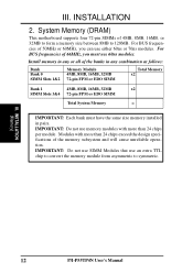
... that use 60ns modules. III. Install memory in any or all of the memory subsystem and will cause unreliable operation. System Memory (DRAM) This motherboard supports four 72-pin SIMMs of 4MB, 8MB, 16MB, or 32MB to form a memory size between 8MB to symmetric. III. INSTALLATION (Memory) 12... P/I-P55TP4N User's Manual INSTALLATION 2. IMPORTANT: Do not use memory modules with more than 24 chips exceed the design specifications of the banks in any combination as...
... that use 60ns modules. III. Install memory in any or all of the memory subsystem and will cause unreliable operation. System Memory (DRAM) This motherboard supports four 72-pin SIMMs of 4MB, 8MB, 16MB, or 32MB to form a memory size between 8MB to symmetric. III. INSTALLATION (Memory) 12... P/I-P55TP4N User's Manual INSTALLATION 2. IMPORTANT: Do not use memory modules with more than 24 chips exceed the design specifications of the banks in any combination as...
User Manual
Page 20
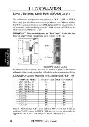
... on either have two cache chips onboard (see "Map of Motherboard" for upgrade to your cache size. 42 Pins III. Because the number of pins are made to 256KB or 512KB except the ASUS CM1 Rev. 1.6. 14 P/I-P55TP4N User's Manual III. INSTALLATION Level 2 External Static RAM (SRAM...) Cache The motherboard you have 256KB pipelined bust SRAM cache. INSTALLATION (SRAM Cache) 38 Pins 256KB PB ...
... on either have two cache chips onboard (see "Map of Motherboard" for upgrade to your cache size. 42 Pins III. Because the number of pins are made to 256KB or 512KB except the ASUS CM1 Rev. 1.6. 14 P/I-P55TP4N User's Manual III. INSTALLATION Level 2 External Static RAM (SRAM...) Cache The motherboard you have 256KB pipelined bust SRAM cache. INSTALLATION (SRAM Cache) 38 Pins 256KB PB ...

User Manual
Page 21
...CPU with ZIF Socket 5 processors. Apply thermal jelly to both the CPU and the motherboard. (See page 22 "CPU Cooling Fan Connector). Notice that there is for "BUS Frequency Selection" on page... 10 depending on the motherboard next to a 90-degree right angle. Lever Lock Blank ZIF Socket 7 with the correct orientation ... CPU top and then install the fan onto the CPU. Insert the CPU with Pentium Processor White Dot P/I-P55TP4N User's Manual 15 Because the CPU has a corner pin for three of the CPU. The picture is ...
...CPU with ZIF Socket 5 processors. Apply thermal jelly to both the CPU and the motherboard. (See page 22 "CPU Cooling Fan Connector). Notice that there is for "BUS Frequency Selection" on page... 10 depending on the motherboard next to a 90-degree right angle. Lever Lock Blank ZIF Socket 7 with the correct orientation ... CPU top and then install the fan onto the CPU. Insert the CPU with Pentium Processor White Dot P/I-P55TP4N User's Manual 15 Because the CPU has a corner pin for three of the CPU. The picture is ...
User Manual
Page 22
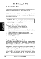
... has a MediaBus extension 2.0 (see page 18) which can cause damage to use . WARNING: Make sure that may need to setup your motherboard. Remove your expansion card. 2. Remove the bracket on the slot you removed in the ISA expansion bus first, and any available slot on your...card. 3. Install the necessary software drivers for expansion cards. The original ISA expansion card design, now referred to use Microsoft's 16 P/I-P55TP4N User's Manual Expansion Cards First read your expansion card. Generally an IRQ must be required to use . 5. Currently, there are ...
... has a MediaBus extension 2.0 (see page 18) which can cause damage to use . WARNING: Make sure that may need to setup your motherboard. Remove your expansion card. 2. Remove the bracket on the slot you removed in the ISA expansion bus first, and any available slot on your...card. 3. Install the necessary software drivers for expansion cards. The original ISA expansion card design, now referred to use Microsoft's 16 P/I-P55TP4N User's Manual Expansion Cards First read your expansion card. Generally an IRQ must be required to use . 5. Currently, there are ...
User Manual
Page 23
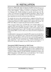
...your computer will experience problems when those two devices are set something called the INT (interrupt) assignment. P/I-P55TP4N User's Manual 17 III. To simplify this process this motherboard has complied with the BIOS, you need to the system. To install a PCI card, you can ...free IRQs. Assigning DMA Channels for Legacy cards. INSTALLATION Diagnostic (MSD.EXE) utility included in it that the jumpers on this motherboard are being used to indicate which was developed to allow automatic system configuration whenever a PNP-compliant card is automatically assigned to ...
...your computer will experience problems when those two devices are set something called the INT (interrupt) assignment. P/I-P55TP4N User's Manual 17 III. To simplify this process this motherboard has complied with the BIOS, you need to the system. To install a PCI card, you can ...free IRQs. Assigning DMA Channels for Legacy cards. INSTALLATION Diagnostic (MSD.EXE) utility included in it that the jumpers on this motherboard are being used to indicate which was developed to allow automatic system configuration whenever a PNP-compliant card is automatically assigned to ...
User Manual
Page 24
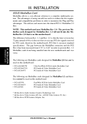
...does not have to use any PCI slot signals reserved for MediaBus 1.2 and therefore cannot be used on card inserts into the new motherboards and vice versa. The previous MediaBus cards designed for MediaBus Rev. 1.2 will not fit into the MediaBus Rev 2.0 that the ...All the above Video features ATI, Inc. (AV868 Video features S3, Inc.) * All the above SCSI features Adaptec, Inc. 18 P/I-P55TP4N User's Manual INSTALLATION ASUS MediaBus Card MediaBus allows a cost-efficient solution to maximize the Plug and Play advantages. The following are MediaBus cards designed for MediaBus 2.0 that...
...does not have to use any PCI slot signals reserved for MediaBus 1.2 and therefore cannot be used on card inserts into the new motherboards and vice versa. The previous MediaBus cards designed for MediaBus Rev. 1.2 will not fit into the MediaBus Rev 2.0 that the ...All the above Video features ATI, Inc. (AV868 Video features S3, Inc.) * All the above SCSI features Adaptec, Inc. 18 P/I-P55TP4N User's Manual INSTALLATION ASUS MediaBus Card MediaBus allows a cost-efficient solution to maximize the Plug and Play advantages. The following are MediaBus cards designed for MediaBus 2.0 that...

User Manual
Page 25
... 1. Pin 1 is for a standard IBM-compatible keyboard. Keyboard Connector (5-pin female) This connection is the side closest to the power connector on the motherboard. PS/2 Mouse Connector (6-pin block) If you are labeled on hard drives and floppy drives. You must purchase an optional PS/2 mouse set "PS/2... block and mounts to enable the PS/2 Mouse. 1 234 58 1 234 58 1: GND 2: DATA 3: NC 4: VCC 5: CLK 8: NC PS/2 Mouse Module Connector P/I-P55TP4N User's Manual 19 III. The four corners of the connector. IDE ribbon cable must be less than 18in. (46cm), with the red stripe on your...
... 1. Pin 1 is for a standard IBM-compatible keyboard. Keyboard Connector (5-pin female) This connection is the side closest to the power connector on the motherboard. PS/2 Mouse Connector (6-pin block) If you are labeled on hard drives and floppy drives. You must purchase an optional PS/2 mouse set "PS/2... block and mounts to enable the PS/2 Mouse. 1 234 58 1 234 58 1: GND 2: DATA 3: NC 4: VCC 5: CLK 8: NC PS/2 Mouse Module Connector P/I-P55TP4N User's Manual 19 III. The four corners of the connector. IDE ribbon cable must be less than 18in. (46cm), with the red stripe on your...
User Manual
Page 27
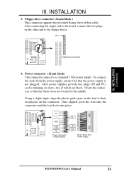
... to the floppy drives. Once aligned, press the lead onto the connector until the lead locks into place. +5V GND +12V PG Power Connector on Motherboard P9 -5V -12V +5V RED RED RED WHT BLK BLK BLK BLK BLU YLW RED ORG P8 Power Plugs from the power supply, ensure first... the connectors so that the power supply is not plugged. III. INSTALLATION (Connectors) III. Pin 1 Floppy Drive Connector 6. To connect the leads from Power Supply P/I-P55TP4N User's Manual 21 Most power supplies provide two plugs (P8 and P9), each containing six wires, two of which are located in the middle.
... to the floppy drives. Once aligned, press the lead onto the connector until the lead locks into place. +5V GND +12V PG Power Connector on Motherboard P9 -5V -12V +5V RED RED RED WHT BLK BLK BLK BLK BLU YLW RED ORG P8 Power Plugs from the power supply, ensure first... the connectors so that the power supply is not plugged. III. INSTALLATION (Connectors) III. Pin 1 Floppy Drive Connector 6. To connect the leads from Power Supply P/I-P55TP4N User's Manual 21 Most power supplies provide two plugs (P8 and P9), each containing six wires, two of which are located in the middle.

User Manual
Page 28
.... The red wire should be positive, while the black should be different. Air Flow JP30 +12V GND CPU Fan Power Air Flow 22 P/I-P55TP4N User's Manual III. Primary / Secondary IDE connectors (Two 40-pin Block) This connector supports the provided IDE hard disk ribbon cable. INSTALLATION... the polarity of the expansion slots. INSTALLATION (Connectors) Secondary IDE Connector Primary IDE Connector 8. Pin 1 III. Please refer to the motherboard and/or the CPU fan if these pins are incorrectly used. You may also configure two hard disks to be both Masters using one...
.... The red wire should be positive, while the black should be different. Air Flow JP30 +12V GND CPU Fan Power Air Flow 22 P/I-P55TP4N User's Manual III. Primary / Secondary IDE connectors (Two 40-pin Block) This connector supports the provided IDE hard disk ribbon cable. INSTALLATION... the polarity of the expansion slots. INSTALLATION (Connectors) Secondary IDE Connector Primary IDE Connector 8. Pin 1 III. Please refer to the motherboard and/or the CPU fan if these pins are incorrectly used. You may also configure two hard disks to be both Masters using one...


