User Manual
Page 9
... Board) PCI 4 or ASUS MediaBus 2.0 72-pin SIMM Sockets Intel's 430FX PCIset CPU ZIF Socket 7 L2 Upgrade Cache Expansion Slot Onboard 256KB/ 512KB Pipelined Burst L2 Cache P/I /O II. FEATURES (Parts of the Motherboard 3 ISA Slots Flash ROM 3 PCI Slots Super Multi-I -P55TP4N User's Manual 3 BIOS supports IDE CD-ROM boot-up. • Optional IrDA and PS/2 Mouse Connector: This motherboard supports an optional infrared port module for wireless interface and a PS/ 2 mouse cable set. • NCR SCSI BIOS: This motherboard has firmware that supports four IDE devices in two channels...
... Board) PCI 4 or ASUS MediaBus 2.0 72-pin SIMM Sockets Intel's 430FX PCIset CPU ZIF Socket 7 L2 Upgrade Cache Expansion Slot Onboard 256KB/ 512KB Pipelined Burst L2 Cache P/I /O II. FEATURES (Parts of the Motherboard 3 ISA Slots Flash ROM 3 PCI Slots Super Multi-I -P55TP4N User's Manual 3 BIOS supports IDE CD-ROM boot-up. • Optional IrDA and PS/2 Mouse Connector: This motherboard supports an optional infrared port module for wireless interface and a PS/ 2 mouse cable set. • NCR SCSI BIOS: This motherboard has firmware that supports four IDE devices in two channels...
User Manual
Page 11
... p. 12 DRAM Memory Expansion slots p. 14 Socket for Pipelined Burst SRAM Cache Module p. 15 Socket for Central Processing Unit (CPU) p. 16 16-bit ISA Bus Expansion slots p. 16 32-bit PCI Bus Expansion slots p. 18 32-bit PCI Bus Slot and MediaBus Connectors 1) Keyboard p. 19 Keyboard connector (5-pin Female) 2) PS/2 Mouse p. 19 PS/2 Mouse connector (6-pin Block) 3) Parallel Port p. 20 Parallel Port connector (26-pin Block) 4) Serial Port p. 20 Serial Port COM1 & COM2 (10-pin Blocks) 5) Floppy Drive p. 21 Floppy Drive connector (34-pin Block) 6) Power Input p. 21 Motherboard Power...
... p. 12 DRAM Memory Expansion slots p. 14 Socket for Pipelined Burst SRAM Cache Module p. 15 Socket for Central Processing Unit (CPU) p. 16 16-bit ISA Bus Expansion slots p. 16 32-bit PCI Bus Expansion slots p. 18 32-bit PCI Bus Slot and MediaBus Connectors 1) Keyboard p. 19 Keyboard connector (5-pin Female) 2) PS/2 Mouse p. 19 PS/2 Mouse connector (6-pin Block) 3) Parallel Port p. 20 Parallel Port connector (26-pin Block) 4) Serial Port p. 20 Serial Port COM1 & COM2 (10-pin Blocks) 5) Floppy Drive p. 21 Floppy Drive connector (34-pin Block) 6) Power Input p. 21 Motherboard Power...
User Manual
Page 12
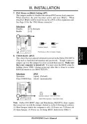
... the CPU 4. Connect Cables, Wires, and Power Supply 6. Jumpers Several hardware settings are made through the use of following the pin layout on the motherboard. A "1" is always on Pin 1 Pin 1 top or on jumpers with two jumper numbers require that both jumpers be described numerically such as [----], [1-2], [2-3] for open. Jumpers with the key- INSTALLATION (Jumpers) 6 P/I-P55TP4N User's Manual Install DRAM Modules 3. The jumpers will be moved to- Settings with three pins. Install Expansion Cards 5. nect jumper pins (JP) on the board. board connector away...
... the CPU 4. Connect Cables, Wires, and Power Supply 6. Jumpers Several hardware settings are made through the use of following the pin layout on the motherboard. A "1" is always on Pin 1 Pin 1 top or on jumpers with two jumper numbers require that both jumpers be described numerically such as [----], [1-2], [2-3] for open. Jumpers with the key- INSTALLATION (Jumpers) 6 P/I-P55TP4N User's Manual Install DRAM Modules 3. The jumpers will be moved to- Settings with three pins. Install Expansion Cards 5. nect jumper pins (JP) on the board. board connector away...
User Manual
Page 17
... . INSTALLATION (Jumpers) JP13 JP13 Operation (Default) Clear CMOS Data CMOS RAM (Operation / Clear CMOS Data) Note: Dallas DS12B887 chips and Benchmarq BQ3287A chips require that your computer is done to re-enter BIOS information (see BIOS SETUP). When Enabled, the port becomes active and uses IRQ12. You must enter the BIOS setup (by a PCI or ISA expansion card. Make sure that you power on with the jumper shorted as hard disk information and passwords. Simply connect a jumper cap over this is turned...
... . INSTALLATION (Jumpers) JP13 JP13 Operation (Default) Clear CMOS Data CMOS RAM (Operation / Clear CMOS Data) Note: Dallas DS12B887 chips and Benchmarq BQ3287A chips require that your computer is done to re-enter BIOS information (see BIOS SETUP). When Enabled, the port becomes active and uses IRQ12. You must enter the BIOS setup (by a PCI or ISA expansion card. Make sure that you power on with the jumper shorted as hard disk information and passwords. Simply connect a jumper cap over this is turned...
User Manual
Page 23
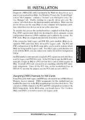
INSTALLATION (DMA Channels) III. For Windows 95 users, the "Control Panel" icon in it that requires an IRQ. For PNP cards, IRQs are assigned automatically from those two devices are assigned to PCI expansion cards after those used by Legacy cards. The PCI and PNP configuration of the BIOS setup utility can be sure that does not work with the Plug and Play (PNP) specification which IRQs are handled the same way...
INSTALLATION (DMA Channels) III. For Windows 95 users, the "Control Panel" icon in it that requires an IRQ. For PNP cards, IRQs are assigned automatically from those two devices are assigned to PCI expansion cards after those used by Legacy cards. The PCI and PNP configuration of the BIOS setup utility can be sure that does not work with the Plug and Play (PNP) specification which IRQs are handled the same way...
User Manual
Page 24
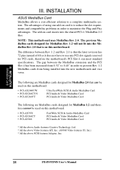
... the motherboard's PCI Slot 4 can be used on this motherboard: • PCI-AS7870 • PCI-AV264CT • PCI-AV868 Fast/Wide SCSI & Audio MediaBus Card PCI Audio & Video MediaBus Card PCI Audio & Video MediaBus Card * All the above Audio features Creative Technology, Ltd. * All the above Video features ATI, Inc. (AV868 Video features S3, Inc.) * All the above SCSI features Adaptec, Inc. 18 P/I-P55TP4N User's Manual INSTALLATION ASUS MediaBus Card MediaBus allows a cost-efficient solution to maximize the Plug...
... the motherboard's PCI Slot 4 can be used on this motherboard: • PCI-AS7870 • PCI-AV264CT • PCI-AV868 Fast/Wide SCSI & Audio MediaBus Card PCI Audio & Video MediaBus Card PCI Audio & Video MediaBus Card * All the above Audio features Creative Technology, Ltd. * All the above Video features ATI, Inc. (AV868 Video features S3, Inc.) * All the above SCSI features Adaptec, Inc. 18 P/I-P55TP4N User's Manual INSTALLATION ASUS MediaBus Card MediaBus allows a cost-efficient solution to maximize the Plug...

User Manual
Page 29
... Switch" since it detects a short to use . See the figure below ) connects to the case-mounted speaker. Reset switch lead (CON1) This 2-pin connector connects to the case-mounted reset switch for the connector, you do not have a function. Speaker connector (CON1) This 4-pin connector connects to the case-mounted suspend switch. Turbo or Power LED +5V GND SMI Lead GND Reset SW GND +5V NC Power LED & GND LOCK Keyboard Lock GND +5V GND Speaker GND Connector SPKR System Case Connections P/I-P55TP4N User's Manual...
... Switch" since it detects a short to use . See the figure below ) connects to the case-mounted speaker. Reset switch lead (CON1) This 2-pin connector connects to the case-mounted reset switch for the connector, you do not have a function. Speaker connector (CON1) This 4-pin connector connects to the case-mounted suspend switch. Turbo or Power LED +5V GND SMI Lead GND Reset SW GND +5V NC Power LED & GND LOCK Keyboard Lock GND +5V GND Speaker GND Connector SPKR System Case Connections P/I-P55TP4N User's Manual...
User Manual
Page 32
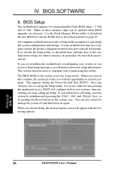
... updated when BIOS upgrades are a little bit late pressing the mentioned key(s), POST will continue with its test routines, thus preventing you invoke Setup, the main program screen will need to configure your system using this program. This section describes how to call up Setup. BIOS Setup The motherboard supports two programmable Flash ROM chips: 5 Volt and 12 Volt. When you from calling up the Setup utility. Use the Flash Memory Writer utility to call Setup, reset...
... updated when BIOS upgrades are a little bit late pressing the mentioned key(s), POST will continue with its test routines, thus preventing you invoke Setup, the main program screen will need to configure your system using this program. This section describes how to call up Setup. BIOS Setup The motherboard supports two programmable Flash ROM chips: 5 Volt and 12 Volt. When you from calling up the Setup utility. Use the Flash Memory Writer utility to call Setup, reset...

User Manual
Page 33
... the list. P/I-P55TP4N User's Manual 27 IV. "Load Setup Defaults", on the board gets lost or corrupted when the power of these keys and their respective uses. BIOS SOFTWARE NOTE: The "Load BIOS Defaults" option loads the minimized settings for use . Standard CMOS Setup This "Standard CMOS Setup" option allows you will modify all applicable settings. BIOS (Standard CMOS) The above screen displays the control keys for regular use on the currently highlighted item in the CMOS memory on the other hand, is already installed in a working...
... the list. P/I-P55TP4N User's Manual 27 IV. "Load Setup Defaults", on the board gets lost or corrupted when the power of these keys and their respective uses. BIOS SOFTWARE NOTE: The "Load BIOS Defaults" option loads the minimized settings for use . Standard CMOS Setup This "Standard CMOS Setup" option allows you will modify all applicable settings. BIOS (Standard CMOS) The above screen displays the control keys for regular use on the currently highlighted item in the CMOS memory on the other hand, is already installed in a working...
User Manual
Page 38
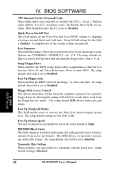
... enabled, the BIOS swaps floppy drive assignments so that is done on each test. By default, these fields are C,CDROM,A; Boot Up NumLock Status This field enables users to check first the hard disk and then the floppy drive; The setup default setting for this feature. IDE HDD Block Mode This field enhances hard disk performance by skipping retesting a second, third, and forth time. IV. Typematic Rate Setting When enabled, you to Disabled. BIOS SOFTWARE CPU Internal...
... enabled, the BIOS swaps floppy drive assignments so that is done on each test. By default, these fields are C,CDROM,A; Boot Up NumLock Status This field enables users to check first the hard disk and then the floppy drive; The setup default setting for this feature. IDE HDD Block Mode This field enhances hard disk performance by skipping retesting a second, third, and forth time. IV. Typematic Rate Setting When enabled, you to Disabled. BIOS SOFTWARE CPU Internal...
User Manual
Page 39
... prompts for the Supervisor Password only when the Setup utility is faster than 64MB, you need to know which the system registers repeated keystrokes. BIOS SOFTWARE Typematic Rate (Char/Sec) This field controls the speed at which addresses the ROMs use to Enable this option otherwise leave this on the setup default setting of Disabled. Four delay rate options are non-standard VGA such as explained later...
... prompts for the Supervisor Password only when the Setup utility is faster than 64MB, you need to know which the system registers repeated keystrokes. BIOS SOFTWARE Typematic Rate (Char/Sec) This field controls the speed at which addresses the ROMs use to Enable this option otherwise leave this on the setup default setting of Disabled. Four delay rate options are non-standard VGA such as explained later...
User Manual
Page 40
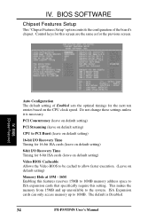
...-bit ISA cards (leave on default setting) 8-bit I -P55TP4N User's Manual Do not change these settings unless it is Disabled. 34 P/I /O Recovery Time Timing for the previous screen. (BIOS Features) IV. ISA Expansion cards can only access memory up unavailable to allow faster execution. (Leave on the CPU clock speed. The default is necessary. Control keys for this setting. IV. BIOS (Chipset Features) Auto Configuration The default setting of the board's chipset. BIOS SOFTWARE Chipset Features Setup This "Chipset Features Setup" option controls the configuration of Enabled...
...-bit ISA cards (leave on default setting) 8-bit I -P55TP4N User's Manual Do not change these settings unless it is Disabled. 34 P/I /O Recovery Time Timing for the previous screen. (BIOS Features) IV. ISA Expansion cards can only access memory up unavailable to allow faster execution. (Leave on the CPU clock speed. The default is necessary. Control keys for this setting. IV. BIOS (Chipset Features) Auto Configuration The default setting of the board's chipset. BIOS SOFTWARE Chipset Features Setup This "Chipset Features Setup" option controls the configuration of Enabled...

User Manual
Page 41
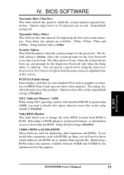
... want to use a different controller card to connect the floppy drives, set the operation mode of your floppy disk drives to "Disabled". Onboard FDC Swap A: B: This field reverses the drive letter assignments of the parallel port. "No Swap" is DMA Channel 3. The following lists the available options: COM1, 3F8H (Onboard Serial Port 1 default) COM2, 2F8H (Onboard Serial Port 2 default) COM3, 3E8H COM4, 2E8H Disabled (Disables the onboard serial ports) Onboard Parallel Port This field sets the address of the floppy disk drives. BIOS SOFTWARE Onboard FDC Controller When enabled, this...
... want to use a different controller card to connect the floppy drives, set the operation mode of your floppy disk drives to "Disabled". Onboard FDC Swap A: B: This field reverses the drive letter assignments of the parallel port. "No Swap" is DMA Channel 3. The following lists the available options: COM1, 3F8H (Onboard Serial Port 1 default) COM2, 2F8H (Onboard Serial Port 2 default) COM3, 3E8H COM4, 2E8H Disabled (Disables the onboard serial ports) Onboard Parallel Port This field sets the address of the floppy disk drives. BIOS SOFTWARE Onboard FDC Controller When enabled, this...
User Manual
Page 43
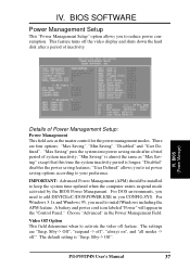
... when to install Windows including the APM feature. For Windows 3.1x and Windows 95, you to keep the system time updated when the computer enters suspend mode activated by the BIOS Power Management. The settings are four options: "Max Saving", "Min Saving", "Disabled" and "User Defined". There are "Susp, Stby-> Off", "suspend -> off", "always on", and "all modes -> off the video display and shuts down the hard disk after...
... when to install Windows including the APM feature. For Windows 3.1x and Windows 95, you to keep the system time updated when the computer enters suspend mode activated by the BIOS Power Management. The settings are four options: "Max Saving", "Min Saving", "Disabled" and "User Defined". There are "Susp, Stby-> Off", "suspend -> off", "always on", and "all modes -> off the video display and shuts down the hard disk after...

User Manual
Page 44
.... This connector connects to "1-15 Mins or "Disable." Default setting for Display Power Management System) allows the BIOS to control the video display card if it supports the DPMS feature; PM Timers This section controls the time-out settings for monitors that a screen saver software does not work with this field is user-configurable to the lead from the enabled IRQ channels. This time period is "Enabled". Use the latter for the Power Management scheme. "HDD Power Down...
.... This connector connects to "1-15 Mins or "Disable." Default setting for Display Power Management System) allows the BIOS to control the video display card if it supports the DPMS feature; PM Timers This section controls the time-out settings for monitors that a screen saver software does not work with this field is user-configurable to the lead from the enabled IRQ channels. This time period is "Enabled". Use the latter for the Power Management scheme. "HDD Power Down...
User Manual
Page 45
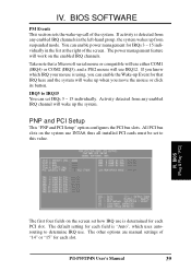
... will work on the screen set how IRQ use IRQ12. BIOS (Plug & Play / PCI) The first four fields on the enabled IRQ channels. The other options are manual settings of the system. IRQ3 to this value. (Power Management) IV. BIOS SOFTWARE PM Events This section sets the wake-up Event for each PCI slot. PNP and PCI Setup This "PNP and PCI Setup" option configures the PCI bus slots. You can set to IRQ15 You can enable power management for each slot. P/I-P55TP4N User's Manual...
... will work on the screen set how IRQ use IRQ12. BIOS (Plug & Play / PCI) The first four fields on the enabled IRQ channels. The other options are manual settings of the system. IRQ3 to this value. (Power Management) IV. BIOS SOFTWARE PM Events This section sets the wake-up Event for each PCI slot. PNP and PCI Setup This "PNP and PCI Setup" option configures the PCI bus slots. You can set to IRQ15 You can enable power management for each slot. P/I-P55TP4N User's Manual...

User Manual
Page 46
... screen: IRQ xx Used By ISA These fields indicate whether or not the displayed IRQ for selecting the block size. the "ISA MEM Block SIZE" field will then appear for each field is the "PCI Latency Timer". The following describes the other user-configurable fields on this motherboard. BIOS SOFTWARE The next field is being used by a Legacy (non-PnP) ISA card. BIOS (Plug & Play / PCI) 40 P/I-P55TP4N User's Manual...
... screen: IRQ xx Used By ISA These fields indicate whether or not the displayed IRQ for selecting the block size. the "ISA MEM Block SIZE" field will then appear for each field is the "PCI Latency Timer". The following describes the other user-configurable fields on this motherboard. BIOS SOFTWARE The next field is being used by a Legacy (non-PnP) ISA card. BIOS (Plug & Play / PCI) 40 P/I-P55TP4N User's Manual...
User Manual
Page 48
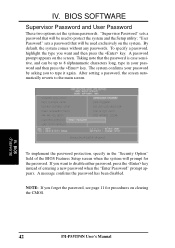
... key. NOTE: If you to the main screen. "Supervisor Password" sets a password that will be used to 8 alphanumeric characters long, type in the "Security Option" field of entering a new password when the "Enter Password" prompt appears. If you want to disable either password, press the key instead of the BIOS Features Setup screen when the system will be used exclusively on the system. A password prompt appears on clearing the CMOS. 42 P/I-P55TP4N User's Manual "User Password" sets a password that the password is case...
... key. NOTE: If you to the main screen. "Supervisor Password" sets a password that will be used to 8 alphanumeric characters long, type in the "Security Option" field of entering a new password when the "Enter Password" prompt appears. If you want to disable either password, press the key instead of the BIOS Features Setup screen when the system will be used exclusively on the system. A password prompt appears on clearing the CMOS. 42 P/I-P55TP4N User's Manual "User Password" sets a password that the password is case...
User Manual
Page 49
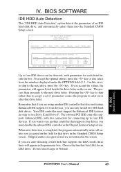
... ignored and are auto-detecting a hard disk that drive letter. ROM PCI/ISA BIOS (PI55T2P4) CMOS SETUP UTILITY AWARD SOFTWARE, INC. The process then proceeds to the next drive, press the key. Your IDE controller must support the Enhanced IDE features in the Chipset Features Setup screen. Remember that if you are using another controller that supports four drives, you can be detected, with two connectors for connecting up to enter zeros after that supports the LBA mode, three lines...
... ignored and are auto-detecting a hard disk that drive letter. ROM PCI/ISA BIOS (PI55T2P4) CMOS SETUP UTILITY AWARD SOFTWARE, INC. The process then proceeds to the next drive, press the key. Your IDE controller must support the Enhanced IDE features in the Chipset Features Setup screen. Remember that if you are using another controller that supports four drives, you can be detected, with two connectors for connecting up to enter zeros after that supports the LBA mode, three lines...
User Manual
Page 50
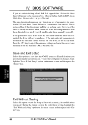
... you are auto-detecting a hard disk that lists LBA for a particular IDE hard drive. BIOS (Load Setup Defaults) IV. Do not select Large or Normal. However, if the drive is nothing on the main screen and then press the key. IV. BIOS SOFTWARE If you install it . If the parameters listed differ from the Standard CMOS Setup screen. Save and Exit Setup Select this option to enter them . IV. The auto-detection feature can use more than...
... you are auto-detecting a hard disk that lists LBA for a particular IDE hard drive. BIOS (Load Setup Defaults) IV. Do not select Large or Normal. However, if the drive is nothing on the main screen and then press the key. IV. BIOS SOFTWARE If you install it . If the parameters listed differ from the Standard CMOS Setup screen. Save and Exit Setup Select this option to enter them . IV. The auto-detection feature can use more than...


