
User Manual
Page 1
P/I-P55TP4N Motherboard USER'S MANUAL
P/I-P55TP4N Motherboard USER'S MANUAL
User Manual
Page 2
... arising from time to the implied warranties or conditions of their respective companies. Product Name: Product Revision: Manual Revision: BIOS Version: Release Date: P/I-P55TP4N 1.01 2.0 #401A0-0201 or later May 1996 II P/I-P55TP4N User's Manual ASUS provides this manual from any kind, either express or implied, including but not limited to time without warranty of the...
... arising from time to the implied warranties or conditions of their respective companies. Product Name: Product Revision: Manual Revision: BIOS Version: Release Date: P/I-P55TP4N 1.01 2.0 #401A0-0201 or later May 1996 II P/I-P55TP4N User's Manual ASUS provides this manual from any kind, either express or implied, including but not limited to time without warranty of the...
User Manual
Page 4
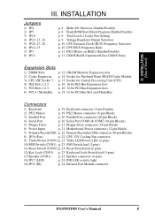
CONTENTS I -P55TP4N User's Manual Jumpers 6 Jumper Settings 8 2. Central Processing Unit (CPU 15 4. FEATURES 2 Features of This Motherboard 2 Parts of the Motherboard 4 Jumpers 5 Expansion Slots 5 Connectors 5 Installation Steps 6 1. External Connectors ...Motherboard 14 3. System Memory (DRAM 12 DRAM Memory Installation Procedures 13 Level 2 External Static RAM (SRAM) Cache 14 Compatible Cache Modules for ISA Cards 17 ASUS MediaBus Card 18 5. Expansion Cards 16 Expansion Card Installation Procedure 16 Assigning IRQs for Expansion Cards 16 Assigning DMA Channels for this...
CONTENTS I -P55TP4N User's Manual Jumpers 6 Jumper Settings 8 2. Central Processing Unit (CPU 15 4. FEATURES 2 Features of This Motherboard 2 Parts of the Motherboard 4 Jumpers 5 Expansion Slots 5 Connectors 5 Installation Steps 6 1. External Connectors ...Motherboard 14 3. System Memory (DRAM 12 DRAM Memory Installation Procedures 13 Level 2 External Static RAM (SRAM) Cache 14 Compatible Cache Modules for ISA Cards 17 ASUS MediaBus Card 18 5. Expansion Cards 16 Expansion Card Installation Procedure 16 Assigning IRQs for Expansion Cards 16 Assigning DMA Channels for this...
User Manual
Page 5
... The PCI-SC200 SCSI Interface Card 56 Setting Up the PCI-SC200 56 Setting the INT Assignment 57 Terminator Settings 57 SCSI ID Numbers 58 P/I-P55TP4N User's Manual V BIOS Setup 26 Standard CMOS Setup 27 Details of Standard CMOS Setup 28 BIOS Features Setup 31 Details of BIOS Features Setup 31 Chipset...
... The PCI-SC200 SCSI Interface Card 56 Setting Up the PCI-SC200 56 Setting the INT Assignment 57 Terminator Settings 57 SCSI ID Numbers 58 P/I-P55TP4N User's Manual V BIOS Setup 26 Standard CMOS Setup 27 Details of Standard CMOS Setup 28 BIOS Features Setup 31 Details of BIOS Features Setup 31 Chipset...

User Manual
Page 6
..., which the receiver is subject to operate this equipment does cause harmful interference to correct the interference by one or more of Communications. VI P/I-P55TP4N User's Manual These limits are designed to provide reasonable protection against harmful interference in the Radio Interference Regulations of the Canadian Department of the following two conditions...
..., which the receiver is subject to operate this equipment does cause harmful interference to correct the interference by one or more of Communications. VI P/I-P55TP4N User's Manual These limits are designed to provide reasonable protection against harmful interference in the Radio Interference Regulations of the Canadian Department of the following two conditions...
User Manual
Page 7
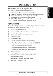
... follows: • Flash Memory Writer utility to a mounting bracket √ 1 parallel ribbon cable with mounting bracket Optional infrared module Optional ASUS pipelined burst cache module Optional PCI-SC200 SCSI card P/I-P55TP4N User's Manual 1 INTRODUCTION How this product III. DMI Utility: BIOS supported Desktop Management Interface VI. Item Checklist Please check that your retailer...
... follows: • Flash Memory Writer utility to a mounting bracket √ 1 parallel ribbon cable with mounting bracket Optional infrared module Optional ASUS pipelined burst cache module Optional PCI-SC200 SCSI card P/I-P55TP4N User's Manual 1 INTRODUCTION How this product III. DMI Utility: BIOS supported Desktop Management Interface VI. Item Checklist Please check that your retailer...
User Manual
Page 8
...or the ASUS MediaBus Card. • ASUS MediaBus Rev 2.0: Features an expansion slot extension shared with PCI Slot 4 for an optional high-performance expansion card which includes two functions in a small package. Two floppy drives of This Motherboard The P/I -P55TP4N User's Manual Upgrades ...are also supported without an external card. The Japanese "Floppy 3 mode" (3.5" 1.2MB) floppy standard is also supported. 2 P/I -P55TP4N is carefully designed for the demanding PC user who wants a great...
...or the ASUS MediaBus Card. • ASUS MediaBus Rev 2.0: Features an expansion slot extension shared with PCI Slot 4 for an optional high-performance expansion card which includes two functions in a small package. Two floppy drives of This Motherboard The P/I -P55TP4N User's Manual Upgrades ...are also supported without an external card. The Japanese "Floppy 3 mode" (3.5" 1.2MB) floppy standard is also supported. 2 P/I -P55TP4N is carefully designed for the demanding PC user who wants a great...
User Manual
Page 9
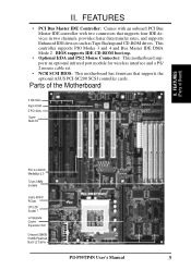
...devices such as Tape Backup and CD-ROM drives. FEATURES (Parts of the Motherboard 3 ISA Slots Flash ROM 3 PCI Slots Super Multi-I -P55TP4N User's Manual 3 This controller supports PIO Modes 3 and 4 and Bus Master IDE DMA Mode 2. FEATURES • PCI Bus Master IDE Controller: Comes ...with an onboard PCI Bus Master IDE controller with two connectors that supports the optional ASUS PCI-SC200 SCSI controller cards. Parts of Board) PCI 4 or ASUS...
...devices such as Tape Backup and CD-ROM drives. FEATURES (Parts of the Motherboard 3 ISA Slots Flash ROM 3 PCI Slots Super Multi-I -P55TP4N User's Manual 3 This controller supports PIO Modes 3 and 4 and Bus Master IDE DMA Mode 2. FEATURES • PCI Bus Master IDE Controller: Comes ...with an onboard PCI Bus Master IDE controller with two connectors that supports the optional ASUS PCI-SC200 SCSI controller cards. Parts of Board) PCI 4 or ASUS...
User Manual
Page 10
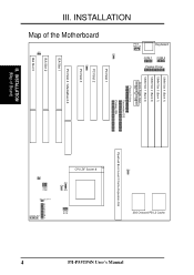
... L2 Cache Pipelined Burst Level 2 Cache Expansion Slot CPU ZIF Socket 8 JP14 JP30 JP15 JP22 JP23 JP24 JP26 JP27 JP28 Case Conn (CON 1) Infrared JP31 4 P/I-P55TP4N User's Manual III.
... L2 Cache Pipelined Burst Level 2 Cache Expansion Slot CPU ZIF Socket 8 JP14 JP30 JP15 JP22 JP23 JP24 JP26 JP27 JP28 Case Conn (CON 1) Infrared JP31 4 P/I-P55TP4N User's Manual III.
User Manual
Page 11
... lead (5-pins) 13) Speaker (CON1) p. 23 Speaker connector (4-pins) 14) JP17 (LED) p. 24 IDE LED activity light 16) JP31 (IR) p. 24 Infrared Port Module connector P/I-P55TP4N User's Manual 5 INSTALLATION (Map of Board) III. III.
... lead (5-pins) 13) Speaker (CON1) p. 23 Speaker connector (4-pins) 14) JP17 (LED) p. 24 IDE LED activity light 16) JP31 (IR) p. 24 Infrared Port Module connector P/I-P55TP4N User's Manual 5 INSTALLATION (Map of Board) III. III.
User Manual
Page 12
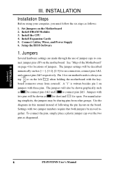
...The jumpers will be sharing pins from yourself. gether. board connector away from other groups. Use the diagrams in this manual instead of the Motherboard" on jumpers with two jumper numbers require that both jumpers be shown graphically such as for short ... pins 2&3 respectively. Settings with three pins. A "1" is always on Pin 1 Pin 1 top or on the board. INSTALLATION (Jumpers) 6 P/I-P55TP4N User's Manual See "Map of following the pin layout on the left when holding the motherboard with the key- Pin 1 for open. III. Install Expansion Cards ...
...The jumpers will be sharing pins from yourself. gether. board connector away from other groups. Use the diagrams in this manual instead of the Motherboard" on jumpers with two jumper numbers require that both jumpers be shown graphically such as for short ... pins 2&3 respectively. Settings with three pins. A "1" is always on Pin 1 Pin 1 top or on the board. INSTALLATION (Jumpers) 6 P/I-P55TP4N User's Manual See "Map of following the pin layout on the left when holding the motherboard with the key- Pin 1 for open. III. Install Expansion Cards ...

User Manual
Page 13
III. Use a grounded wrist strap before handling computer components. 4. INSTALLATION (Jumpers) P/I-P55TP4N User's Manual 7 Unplug your motherboard. Place components on a grounded antistatic pad or on the bag that came with the component whenever you work on your computer. 1. INSTALLATION ...
III. Use a grounded wrist strap before handling computer components. 4. INSTALLATION (Jumpers) P/I-P55TP4N User's Manual 7 Unplug your motherboard. Place components on a grounded antistatic pad or on the bag that came with the component whenever you work on your computer. 1. INSTALLATION ...
User Manual
Page 14
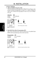
...-I/O Selection (JP4) You can selectively disable each onboard Multi-I/O item (floppy, serial, parallel, and IrDA) through BIOS (see page 35) or disable all Multi-I -P55TP4N User's Manual Flash ROM Boot Block Programming (JP5) This sets the operation mode of the boot block area of the BIOS Flash ROM to use your own...
...-I/O Selection (JP4) You can selectively disable each onboard Multi-I/O item (floppy, serial, parallel, and IrDA) through BIOS (see page 35) or disable all Multi-I -P55TP4N User's Manual Flash ROM Boot Block Programming (JP5) This sets the operation mode of the boot block area of the BIOS Flash ROM to use your own...

User Manual
Page 15
... 512KB. INSTALLATION 3. Total Level 2 Cache Size Setting (JP16) This jumper sets the total amount of Motherboard" for installation procedures. An "ASUS" or "COAST" cache module can be used to upgrade the 256KB version to the CPU. Regardless of your cache combination, set the voltage...Jumpers) JP22 JP23 JP24 JP22 JP23 JP24 STD 3.3V - 3.465V (Default) VRE 3.4V - 3.6V Voltage Regulator Output Selection (STD / VRE) P/I-P55TP4N User's Manual 9 If there is no onboard cache, you have either 256KB or 512KB. III. IMPORTANT: See page 14 "SRAM Cache" for locations), then you must...
... 512KB. INSTALLATION 3. Total Level 2 Cache Size Setting (JP16) This jumper sets the total amount of Motherboard" for installation procedures. An "ASUS" or "COAST" cache module can be used to upgrade the 256KB version to the CPU. Regardless of your cache combination, set the voltage...Jumpers) JP22 JP23 JP24 JP22 JP23 JP24 STD 3.3V - 3.465V (Default) VRE 3.4V - 3.6V Voltage Regulator Output Selection (STD / VRE) P/I-P55TP4N User's Manual 9 If there is no onboard cache, you have either 256KB or 512KB. III. IMPORTANT: See page 14 "SRAM Cache" for locations), then you must...

User Manual
Page 16
... 2.0x 66MHz [2-3] [1-2] [2-3] [open] [short] 2.0x 60MHz [1-2] [2-3] [2-3] [open] [short] 100MHz 90MHz 75MHz 1.5x 66MHz 1.5x 60MHz 1.5x 50MHz [2-3] [1-2] [2-3] [open] [open] [1-2] [2-3] [2-3] [open] [open] [2-3] [2-3] [1-2] [open] [open] 10 P/I-P55TP4N User's Manual These must be set the frequency ratio between the Internal frequency of the CPU's External frequency (or BUS Clock). The BUS Clock times the BUS...
... 2.0x 66MHz [2-3] [1-2] [2-3] [open] [short] 2.0x 60MHz [1-2] [2-3] [2-3] [open] [short] 100MHz 90MHz 75MHz 1.5x 66MHz 1.5x 60MHz 1.5x 50MHz [2-3] [1-2] [2-3] [open] [open] [1-2] [2-3] [2-3] [open] [open] [2-3] [2-3] [1-2] [open] [open] 10 P/I-P55TP4N User's Manual These must be set the frequency ratio between the Internal frequency of the CPU's External frequency (or BUS Clock). The BUS Clock times the BUS...
User Manual
Page 17
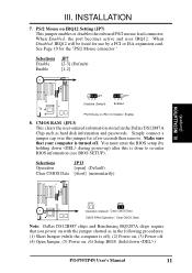
... require that your computer is done to re-enter BIOS information (see BIOS SETUP). When Disabled, IRQ12 will be freed for use by holding down ) P/I-P55TP4N User's Manual 11 INSTALLATION 7. Make sure that you power on with the jumper shorted as hard disk information and passwords. Selections JP13 Operation [open] (Default) Clear...
... require that your computer is done to re-enter BIOS information (see BIOS SETUP). When Disabled, IRQ12 will be freed for use by holding down ) P/I-P55TP4N User's Manual 11 INSTALLATION 7. Make sure that you power on with the jumper shorted as hard disk information and passwords. Selections JP13 Operation [open] (Default) Clear...
User Manual
Page 18
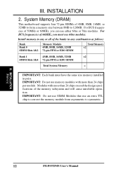
... use an extra TTL chip to convert the memory module from asymmetric to 128MB. Modules with more than 24 chips per module. INSTALLATION (Memory) 12 P/I-P55TP4N User's Manual III.
... use an extra TTL chip to convert the memory module from asymmetric to 128MB. Modules with more than 24 chips per module. INSTALLATION (Memory) 12 P/I-P55TP4N User's Manual III.

User Manual
Page 19
... memory module, squeeze both "Metal Clips" outwards and rock the module out of the SIMM memory modules. 1234 III. INSTALLATION DRAM Memory Installation Procedures: 1. P/I-P55TP4N User's Manual 13 III. Press the memory module firmly into place starting from a 45 degree angle making sure that it clicks into a vertical position so that all...
... memory module, squeeze both "Metal Clips" outwards and rock the module out of the SIMM memory modules. 1234 III. INSTALLATION DRAM Memory Installation Procedures: 1. P/I-P55TP4N User's Manual 13 III. Press the memory module firmly into place starting from a 45 degree angle making sure that it clicks into a vertical position so that all...
User Manual
Page 20
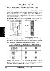
...) 38 Pins 256KB PB Cache Module Insert the module as shown. Compatible Cache Modules for Motherboard PCB 1.01 SIMM Cache Module ASUS CM1 Rev 1.0 ASUS CM1 Rev 1.3 ASUS CM4 Rev 1.5 ASUS CM1 Rev 1.6 ASUS CM1 Rev 3.0 COAST 1.1 COAST 1.2 COAST 1.3 COAST 2.0 COAST 2.1 COAST 3.0 256KB to 512KB No No No Yes Yes ... 0KB version can be used to upgrade the 256KB version to 512KB and the 0KB version to 256KB or 512KB except the ASUS CM1 Rev. 1.6. 14 P/I-P55TP4N User's Manual Most likely you will only fit in the orientation as shown. A cache module can use all modules for locations), then ...
...) 38 Pins 256KB PB Cache Module Insert the module as shown. Compatible Cache Modules for Motherboard PCB 1.01 SIMM Cache Module ASUS CM1 Rev 1.0 ASUS CM1 Rev 1.3 ASUS CM4 Rev 1.5 ASUS CM1 Rev 1.6 ASUS CM1 Rev 3.0 COAST 1.1 COAST 1.2 COAST 1.3 COAST 2.0 COAST 2.1 COAST 3.0 256KB to 512KB No No No Yes Yes ... 0KB version can be used to upgrade the 256KB version to 512KB and the 0KB version to 256KB or 512KB except the ASUS CM1 Rev. 1.6. 14 P/I-P55TP4N User's Manual Most likely you will only fit in the orientation as shown. A cache module can use all modules for locations), then ...

User Manual
Page 21
... ZIF Socket 7 with the correct orientation as shown. Apply thermal jelly to a 90-degree right angle. Insert the CPU with Pentium Processor White Dot P/I-P55TP4N User's Manual 15 III. Locate the ZIF socket and open it to that there is for three of the CPU. If this is not the case then...
... ZIF Socket 7 with the correct orientation as shown. Apply thermal jelly to a 90-degree right angle. Insert the CPU with Pentium Processor White Dot P/I-P55TP4N User's Manual 15 III. Locate the ZIF socket and open it to that there is for three of the CPU. If this is not the case then...


