
User Manual
Page 1
P/I-P55TP4N Motherboard USER'S MANUAL
P/I-P55TP4N Motherboard USER'S MANUAL

User Manual
Page 2
... or copyrights of their respective companies. Product Name: Product Revision: Manual Revision: BIOS Version: Release Date: P/I-P55TP4N 1.01 2.0 #401A0-0201 or later May 1996 II P/I-P55TP4N User's Manual USER'S NOTICE No part of this product, including the product and software may be liable for... download the BIOS file from time to as ASUS) except documentation kept by the purchaser for additions or corrections represented by the digit before the period and for backup purposes. Your BIOS version displayed on the motherboard itself. ASUS provides this manual from a BBS or FTP server...
... or copyrights of their respective companies. Product Name: Product Revision: Manual Revision: BIOS Version: Release Date: P/I-P55TP4N 1.01 2.0 #401A0-0201 or later May 1996 II P/I-P55TP4N User's Manual USER'S NOTICE No part of this product, including the product and software may be liable for... download the BIOS file from time to as ASUS) except documentation kept by the purchaser for additions or corrections represented by the digit before the period and for backup purposes. Your BIOS version displayed on the motherboard itself. ASUS provides this manual from a BBS or FTP server...
User Manual
Page 4
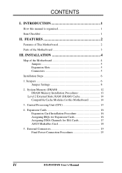
INTRODUCTION 1 How this Motherboard 14 3. INSTALLATION 4 Map of the Motherboard 3 III. Jumpers 6 Jumper Settings 8 2. External Connectors 19 Final Power Connection Procedures 25 IV P/I . CONTENTS I -P55TP4N User's Manual Central Processing Unit (CPU 15 4. Expansion Cards 16 Expansion Card Installation ... 13 Level 2 External Static RAM (SRAM) Cache 14 Compatible Cache Modules for ISA Cards 17 ASUS MediaBus Card 18 5. FEATURES 2 Features of This Motherboard 2 Parts of the Motherboard 4 Jumpers 5 Expansion Slots 5 Connectors 5 Installation Steps 6 1.
INTRODUCTION 1 How this Motherboard 14 3. INSTALLATION 4 Map of the Motherboard 3 III. Jumpers 6 Jumper Settings 8 2. External Connectors 19 Final Power Connection Procedures 25 IV P/I . CONTENTS I -P55TP4N User's Manual Central Processing Unit (CPU 15 4. Expansion Cards 16 Expansion Card Installation ... 13 Level 2 External Static RAM (SRAM) Cache 14 Compatible Cache Modules for ISA Cards 17 ASUS MediaBus Card 18 5. FEATURES 2 Features of This Motherboard 2 Parts of the Motherboard 4 Jumpers 5 Expansion Slots 5 Connectors 5 Installation Steps 6 1.
User Manual
Page 7
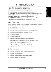
...files √ This user's manual Optional PS/2 mouse cable with mounting bracket Optional infrared module Optional ASUS pipelined burst cache module Optional PCI-SC200 SCSI card P/I-P55TP4N User's Manual 1 I . INTRODUCTION How this product III. Introduction: Manual information and checklist II.... Desktop Management Interface VI. If you discover damaged or missing items, please contact your package is divided into the following sections: I -P55TP4N motherboard √ 2 serial port ribbon cables attached to a mounting bracket √ 1 parallel ribbon cable with mounting bracket √ 1 ...
...files √ This user's manual Optional PS/2 mouse cable with mounting bracket Optional infrared module Optional ASUS pipelined burst cache module Optional PCI-SC200 SCSI card P/I-P55TP4N User's Manual 1 I . INTRODUCTION How this product III. Introduction: Manual information and checklist II.... Desktop Management Interface VI. If you discover damaged or missing items, please contact your package is divided into the following sections: I -P55TP4N motherboard √ 2 serial port ribbon cables attached to a mounting bracket √ 1 parallel ribbon cable with mounting bracket √ 1 ...
User Manual
Page 8
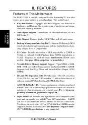
...Pentium CPU on a ZIF Socket 7. • Intel Chipset: Features Intel's 430FX PCIset with EPP and ECP capabilities. FEATURES Features of This Motherboard The P/I-P55TP4N is also supported. 2 P/I /O subsystems. • Desktop Management Interface (DMI): Supports DMI through a Synchronous SRAM cache module. (See page...a higher level of compatibility. • L2 Cache: Provides the option of either an standard PCI card or the ASUS MediaBus Card. • ASUS MediaBus Rev 2.0: Features an expansion slot extension shared with PCI Slot 4 for wireless connections. Two floppy drives of ...
...Pentium CPU on a ZIF Socket 7. • Intel Chipset: Features Intel's 430FX PCIset with EPP and ECP capabilities. FEATURES Features of This Motherboard The P/I-P55TP4N is also supported. 2 P/I /O subsystems. • Desktop Management Interface (DMI): Supports DMI through a Synchronous SRAM cache module. (See page...a higher level of compatibility. • L2 Cache: Provides the option of either an standard PCI card or the ASUS MediaBus Card. • ASUS MediaBus Rev 2.0: Features an expansion slot extension shared with PCI Slot 4 for wireless connections. Two floppy drives of ...
User Manual
Page 9
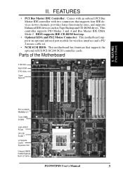
...) PCI 4 or ASUS MediaBus 2.0 72-pin SIMM Sockets Intel's 430FX PCIset CPU ZIF Socket 7 L2 Upgrade Cache Expansion Slot Onboard 256KB/ 512KB Pipelined Burst L2 Cache P/I /O II. II. FEATURES (Parts of the Motherboard 3 ISA Slots Flash ROM 3 PCI Slots Super Multi-I -P55TP4N User's Manual 3 ...FEATURES • PCI Bus Master IDE Controller: Comes with an onboard PCI Bus Master IDE controller with two connectors that supports the optional ASUS PCI-SC200 SCSI controller cards.
...) PCI 4 or ASUS MediaBus 2.0 72-pin SIMM Sockets Intel's 430FX PCIset CPU ZIF Socket 7 L2 Upgrade Cache Expansion Slot Onboard 256KB/ 512KB Pipelined Burst L2 Cache P/I /O II. II. FEATURES (Parts of the Motherboard 3 ISA Slots Flash ROM 3 PCI Slots Super Multi-I -P55TP4N User's Manual 3 ...FEATURES • PCI Bus Master IDE Controller: Comes with an onboard PCI Bus Master IDE controller with two connectors that supports the optional ASUS PCI-SC200 SCSI controller cards.
User Manual
Page 10
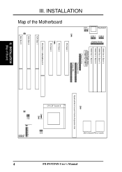
III. INSTALLATION (Map of the Motherboard JP7 JP4 JP5 PS/2 Mouse Keyboard COM 1 COM 2 Parallel Printer SIMM Slot 4 (Bank 1) SIMM Slot 3 (Bank 1) SIMM Slot 2 (Bank 0) SIMM Slot 1 (Bank 0) Board Power Input ... L2 Cache Pipelined Burst Level 2 Cache Expansion Slot CPU ZIF Socket 8 JP14 JP30 JP15 JP22 JP23 JP24 JP26 JP27 JP28 Case Conn (CON 1) Infrared JP31 4 P/I-P55TP4N User's Manual
III. INSTALLATION (Map of the Motherboard JP7 JP4 JP5 PS/2 Mouse Keyboard COM 1 COM 2 Parallel Printer SIMM Slot 4 (Bank 1) SIMM Slot 3 (Bank 1) SIMM Slot 2 (Bank 0) SIMM Slot 1 (Bank 0) Board Power Input ... L2 Cache Pipelined Burst Level 2 Cache Expansion Slot CPU ZIF Socket 8 JP14 JP30 JP15 JP22 JP23 JP24 JP26 JP27 JP28 Case Conn (CON 1) Infrared JP31 4 P/I-P55TP4N User's Manual
User Manual
Page 11
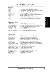
... (26-pin Block) 4) Serial Port p. 20 Serial Port COM1 & COM2 (10-pin Blocks) 5) Floppy Drive p. 21 Floppy Drive connector (34-pin Block) 6) Power Input p. 21 Motherboard Power connector (12-pin Block) 7) Primary/Second IDE p. 22 Primary/Secondary IDE connector (40-pin Blocks) 8) JP30 (Fan) p. 22 CPU 12V Cooling Fan connector 9) Turbo... lead (5-pins) 13) Speaker (CON1) p. 23 Speaker connector (4-pins) 14) JP17 (LED) p. 24 IDE LED activity light 16) JP31 (IR) p. 24 Infrared Port Module connector P/I-P55TP4N User's Manual 5 III.
... (26-pin Block) 4) Serial Port p. 20 Serial Port COM1 & COM2 (10-pin Blocks) 5) Floppy Drive p. 21 Floppy Drive connector (34-pin Block) 6) Power Input p. 21 Motherboard Power connector (12-pin Block) 7) Primary/Second IDE p. 22 Primary/Secondary IDE connector (40-pin Blocks) 8) JP30 (Fan) p. 22 CPU 12V Cooling Fan connector 9) Turbo... lead (5-pins) 13) Speaker (CON1) p. 23 Speaker connector (4-pins) 14) JP17 (LED) p. 24 IDE LED activity light 16) JP31 (IR) p. 24 Infrared Port Module connector P/I-P55TP4N User's Manual 5 III.
User Manual
Page 12
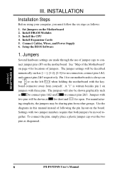
... made through the use of following the pin layout on the motherboard. The jumper settings will be described numerically such as [----], [1-2], [2-3] for locations of the Motherboard" on the left when holding the motherboard with two jumper numbers require that both jumpers be sharing pins from... a plastic jumper cap over the two pins as to connect pins 1&2 and to - Setup the BIOS Software 1. INSTALLATION (Jumpers) 6 P/I-P55TP4N User's Manual ing simplicity, the jumpers may be moved to connect pins 2&3. III. III. Set Jumpers on jumpers with two pins will also...
... made through the use of following the pin layout on the motherboard. The jumper settings will be described numerically such as [----], [1-2], [2-3] for locations of the Motherboard" on the left when holding the motherboard with two jumper numbers require that both jumpers be sharing pins from... a plastic jumper cap over the two pins as to connect pins 1&2 and to - Setup the BIOS Software 1. INSTALLATION (Jumpers) 6 P/I-P55TP4N User's Manual ing simplicity, the jumpers may be moved to connect pins 2&3. III. III. Set Jumpers on jumpers with two pins will also...

User Manual
Page 13
... jumper caps over these will cause damage to touch the IC chips. 3. Unplug your computer. 1. INSTALLATION (Jumpers) P/I-P55TP4N User's Manual 7 To protect the motherboard and other components against damage from jumpers in "Map of the Motherboard" on page 4. Place components on a grounded antistatic pad or on the bag that came with the component...
... jumper caps over these will cause damage to touch the IC chips. 3. Unplug your computer. 1. INSTALLATION (Jumpers) P/I-P55TP4N User's Manual 7 To protect the motherboard and other components against damage from jumpers in "Map of the Motherboard" on page 4. Place components on a grounded antistatic pad or on the bag that came with the component...

User Manual
Page 15
... [short] [open] III. Regardless of either 256KB or 512KB. III. An "ASUS" or "COAST" cache module can be used to upgrade the 256KB version to the total amount of Motherboard" for installation procedures. Voltage Regulator Output Selection (JP22, 23, 24) These jumpers set... the following jumpers according to 512KB. INSTALLATION (Jumpers) JP22 JP23 JP24 JP22 JP23 JP24 STD 3.3V - 3.465V (Default) VRE 3.4V - 3.6V Voltage Regulator Output Selection (STD / VRE) P/I-P55TP4N ...
... [short] [open] III. Regardless of either 256KB or 512KB. III. An "ASUS" or "COAST" cache module can be used to upgrade the 256KB version to the total amount of Motherboard" for installation procedures. Voltage Regulator Output Selection (JP22, 23, 24) These jumpers set... the following jumpers according to 512KB. INSTALLATION (Jumpers) JP22 JP23 JP24 JP22 JP23 JP24 STD 3.3V - 3.465V (Default) VRE 3.4V - 3.6V Voltage Regulator Output Selection (STD / VRE) P/I-P55TP4N ...
User Manual
Page 18
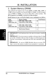
.... IMPORTANT: Do not use SIMM Modules that use either 60ns or 70ns modules. Modules with more than 24 chips per module. INSTALLATION (Memory) 12 P/I-P55TP4N User's Manual System Memory (DRAM) This motherboard supports four 72-pin SIMMs of 4MB, 8MB, 16MB, or 32MB to form a memory size between 8MB to symmetric. III.
.... IMPORTANT: Do not use SIMM Modules that use either 60ns or 70ns modules. Modules with more than 24 chips per module. INSTALLATION (Memory) 12 P/I-P55TP4N User's Manual System Memory (DRAM) This motherboard supports four 72-pin SIMMs of 4MB, 8MB, 16MB, or 32MB to form a memory size between 8MB to symmetric. III.
User Manual
Page 20
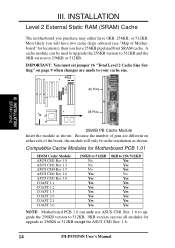
... INSTALLATION (SRAM Cache) 38 Pins 256KB PB Cache Module Insert the module as shown. Compatible Cache Modules for Motherboard PCB 1.01 SIMM Cache Module ASUS CM1 Rev 1.0 ASUS CM1 Rev 1.3 ASUS CM4 Rev 1.5 ASUS CM1 Rev 1.6 ASUS CM1 Rev 3.0 COAST 1.1 COAST 1.2 COAST 1.3 COAST 2.0 COAST 2.1 COAST 3.0 256KB to 512KB No No... No Yes Yes Yes Yes Yes Yes Yes Yes 0KB to 256KB or 512KB except the ASUS CM1 Rev. 1.6. 14 P/I-P55TP4N User's Manual IMPORTANT: You must set jumper 16 "Total Level 2 Cache Size Setting" on either have two cache chips onboard (...
... INSTALLATION (SRAM Cache) 38 Pins 256KB PB Cache Module Insert the module as shown. Compatible Cache Modules for Motherboard PCB 1.01 SIMM Cache Module ASUS CM1 Rev 1.0 ASUS CM1 Rev 1.3 ASUS CM4 Rev 1.5 ASUS CM1 Rev 1.6 ASUS CM1 Rev 3.0 COAST 1.1 COAST 1.2 COAST 1.3 COAST 2.0 COAST 2.1 COAST 3.0 256KB to 512KB No No... No Yes Yes Yes Yes Yes Yes Yes Yes 0KB to 256KB or 512KB except the ASUS CM1 Rev. 1.6. 14 P/I-P55TP4N User's Manual IMPORTANT: You must set jumper 16 "Total Level 2 Cache Size Setting" on either have two cache chips onboard (...

User Manual
Page 21
... system and remove its cover. INSTALLATION (CPU) III. Central Processing Unit (CPU) The motherboard provides a 321-pin ZIF Socket 7 that corner. If this is backwards compatible with Pentium Processor White Dot P/I-P55TP4N User's Manual 15 Insert the CPU with the white dot as shown. WARNING: Without ... as shown. III. INSTALLATION 3. Apply thermal jelly to both the CPU and the motherboard. (See page 22 "CPU Cooling Fan Connector). To install a CPU, first turn on the motherboard next to insert the CPU. Use the notched corner of the CPU fan, no ...
... system and remove its cover. INSTALLATION (CPU) III. Central Processing Unit (CPU) The motherboard provides a 321-pin ZIF Socket 7 that corner. If this is backwards compatible with Pentium Processor White Dot P/I-P55TP4N User's Manual 15 Insert the CPU with the white dot as shown. WARNING: Without ... as shown. III. INSTALLATION 3. Apply thermal jelly to both the CPU and the motherboard. (See page 22 "CPU Cooling Fan Connector). To install a CPU, first turn on the motherboard next to insert the CPU. Use the notched corner of the CPU fan, no ...
User Manual
Page 22
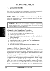
...optional multifunctional card) but most of ISA cards. III. INSTALLATION 4. Secure the card on the slot you intend to use Microsoft's 16 P/I-P55TP4N User's Manual Replace the computer's cover. 8. Setup the BIOS if necessary. 9. Assigning IRQs for your expansion card. 2. System IRQs are...exclusively assigned to your computer's cover. 4. Power supplies contain power reserves which can cause damage to one use . 5. Remove your motherboard. Generally an IRQ must be required to as "Legacy" ISA cards, requires that you unplug your specific card. The original ISA ...
...optional multifunctional card) but most of ISA cards. III. INSTALLATION 4. Secure the card on the slot you intend to use Microsoft's 16 P/I-P55TP4N User's Manual Replace the computer's cover. 8. Setup the BIOS if necessary. 9. Assigning IRQs for your expansion card. 2. System IRQs are...exclusively assigned to your computer's cover. 4. Power supplies contain power reserves which can cause damage to one use . 5. Remove your motherboard. Generally an IRQ must be required to as "Legacy" ISA cards, requires that you unplug your specific card. The original ISA ...
User Manual
Page 23
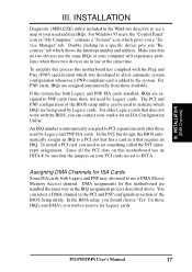
.... In the PCI bus design, the BIOS automatically assigns an IRQ to use a DMA (Direct Memory Access) channel. P/I-P55TP4N User's Manual 17 Since all the PCI slots on this motherboard use at the same time. If the system has both Legacy and PNP may also need to the system. INSTALLATION... IRQ's and DMA's you a "Device Manager" tab. The PCI and PNP configuration of your vendor for Legacy cards. To simplify this process this motherboard are assigned to reserve for an ISA Configuration Utility. An IRQ number is added to set to INT A. For PNP cards, IRQs are being used...
.... In the PCI bus design, the BIOS automatically assigns an IRQ to use a DMA (Direct Memory Access) channel. P/I-P55TP4N User's Manual 17 Since all the PCI slots on this motherboard use at the same time. If the system has both Legacy and PNP may also need to the system. INSTALLATION... IRQ's and DMA's you a "Device Manager" tab. The PCI and PNP configuration of your vendor for Legacy cards. To simplify this process this motherboard are assigned to reserve for an ISA Configuration Utility. An IRQ number is added to set to INT A. For PNP cards, IRQs are being used...
User Manual
Page 24
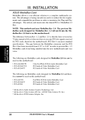
.... (AV868 Video features S3, Inc.) * All the above SCSI features Adaptec, Inc. 18 P/I-P55TP4N User's Manual The gap between Rev. 1.2 and Rev. 2.0 is that can meet standard specifications...0.40" in order to a complete multimedia system. INSTALLATION (MediaBus Card) III. INSTALLATION ASUS MediaBus Card MediaBus allows a cost-efficient solution to maximize the Plug and Play advantages. ...The following are MediaBus cards designed for MediaBus 1.2 and therefore cannot be used on this motherboard: • PCI-AS2940UW • PCI-AV264CT-N • PCI-AV264VT Ultra Fast/Wide ...
.... (AV868 Video features S3, Inc.) * All the above SCSI features Adaptec, Inc. 18 P/I-P55TP4N User's Manual The gap between Rev. 1.2 and Rev. 2.0 is that can meet standard specifications...0.40" in order to a complete multimedia system. INSTALLATION (MediaBus Card) III. INSTALLATION ASUS MediaBus Card MediaBus allows a cost-efficient solution to maximize the Plug and Play advantages. ...The following are MediaBus cards designed for MediaBus 1.2 and therefore cannot be used on this motherboard: • PCI-AS2940UW • PCI-AV264CT-N • PCI-AV264VT Ultra Fast/Wide ...

User Manual
Page 25
... Plug from the first connector. 1. IDE ribbon cable must also set which connects to the 6 pin block and mounts to the power connector on the motherboard. III. INSTALLATION 5. Keyboard Connector (5-pin female) This connection is the side closest to an open slot on the Pin 1 side of the connectors are using... "PS/2 Mouse Selection" on page 11 to enable the PS/2 Mouse. 1 234 58 1 234 58 1: GND 2: DATA 3: NC 4: VCC 5: CLK 8: NC PS/2 Mouse Module Connector P/I-P55TP4N User's Manual 19
... Plug from the first connector. 1. IDE ribbon cable must also set which connects to the 6 pin block and mounts to the power connector on the motherboard. III. INSTALLATION 5. Keyboard Connector (5-pin female) This connection is the side closest to an open slot on the Pin 1 side of the connectors are using... "PS/2 Mouse Selection" on page 11 to enable the PS/2 Mouse. 1 234 58 1 234 58 1: GND 2: DATA 3: NC 4: VCC 5: CLK 8: NC PS/2 Mouse Module Connector P/I-P55TP4N User's Manual 19
User Manual
Page 27
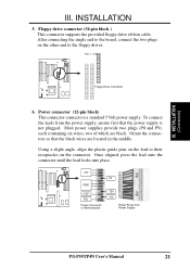
... connector until the lead locks into place. +5V GND +12V PG Power Connector on the connector. INSTALLATION 5. To connect the leads from Power Supply P/I-P55TP4N User's Manual 21 Pin 1 Floppy Drive Connector 6. Floppy drive connector (34-pin block ) This connector supports the provided floppy drive ribbon cable. Using... a slight angle, align the plastic guide pins on the lead to their receptacles on Motherboard P9 -5V -12V +5V RED RED RED WHT BLK BLK BLK BLK BLU YLW RED ORG P8 Power Plugs from the power supply, ...
... connector until the lead locks into place. +5V GND +12V PG Power Connector on the connector. INSTALLATION 5. To connect the leads from Power Supply P/I-P55TP4N User's Manual 21 Pin 1 Floppy Drive Connector 6. Floppy drive connector (34-pin block ) This connector supports the provided floppy drive ribbon cable. Using... a slight angle, align the plastic guide pins on the lead to their receptacles on Motherboard P9 -5V -12V +5V RED RED RED WHT BLK BLK BLK BLK BLU YLW RED ORG P8 Power Plugs from the power supply, ...

User Manual
Page 28
...to the board taking into consideration the polarity of 500mAMP (6WATT) or less. Air Flow JP30 +12V GND CPU Fan Power Air Flow 22 P/I-P55TP4N User's Manual If you install two hard disks, you must configure the second drive to the expansion slots. The red wire should be positive, while... on the primary IDE connector and another ribbon cable on the fan manufacturer, the wiring and plug may also configure two hard disks to the motherboard and/or the CPU fan if these pins are incorrectly used. You may be ground. CPU cooling fan connector (JP30) This connector supports a CPU...
...to the board taking into consideration the polarity of 500mAMP (6WATT) or less. Air Flow JP30 +12V GND CPU Fan Power Air Flow 22 P/I-P55TP4N User's Manual If you install two hard disks, you must configure the second drive to the expansion slots. The red wire should be positive, while... on the primary IDE connector and another ribbon cable on the fan manufacturer, the wiring and plug may also configure two hard disks to the motherboard and/or the CPU fan if these pins are incorrectly used. You may be ground. CPU cooling fan connector (JP30) This connector supports a CPU...


