
NCCH-DR User Manual English Version
Page 1
Motherboard NCCH-DR Series
Motherboard NCCH-DR Series

NCCH-DR User Manual English Version
Page 3
... vi Safety information vii About this guide viii Typography ix NCCH-DR Series specifications summary x Chapter 1: Product introduction 1.1 Welcome 1-1 1.2 Package contents 1-1 1.3 Special features 1-2 1.3.1 Product highlights 1-2 1.3.2 Innovative ASUS features 1-4 Chapter 2: Hardware information 2.1 Before you proceed 2-1 2.2 Motherboard overview 2-2 2.2.1 2.2.2 2.2.3 Placement direction 2-2 Screw holes 2-2 CPU heatsink weight support 2-3 2.2.4 Motherboard layout 2-9 2.2.5 Layout contents 2-11 2.3 Central Processing Unit (CPU 2-13 2.3.1 Installling...
... vi Safety information vii About this guide viii Typography ix NCCH-DR Series specifications summary x Chapter 1: Product introduction 1.1 Welcome 1-1 1.2 Package contents 1-1 1.3 Special features 1-2 1.3.1 Product highlights 1-2 1.3.2 Innovative ASUS features 1-4 Chapter 2: Hardware information 2.1 Before you proceed 2-1 2.2 Motherboard overview 2-2 2.2.1 2.2.2 2.2.3 Placement direction 2-2 Screw holes 2-2 CPU heatsink weight support 2-3 2.2.4 Motherboard layout 2-9 2.2.5 Layout contents 2-11 2.3 Central Processing Unit (CPU 2-13 2.3.1 Installling...

NCCH-DR User Manual English Version
Page 7
... that your power supply is broken, do not try to fix it , carefully read all power cables are connected. Operation safety • Before installing the motherboard and adding devices on a stable surface. • If you add a device. • Before connecting or removing signal cables from the...
... that your power supply is broken, do not try to fix it , carefully read all power cables are connected. Operation safety • Before installing the motherboard and adding devices on a stable surface. • If you add a device. • Before connecting or removing signal cables from the...
NCCH-DR User Manual English Version
Page 8
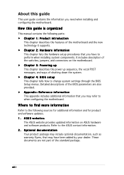
...the features of the switches, jumpers, and connectors on ASUS hardware and software products. How this guide This user guide contains the information you may have to when configuring the motherboard. Optional documentation Your product package may include optional documentation... Reference information This appendix includes additional information that may refer to perform when installing system components. ASUS websites The ASUS website provides updated information on the motherboard. • Chapter 3: Powering up This chapter describes the power up sequence, the vocal POST...
...the features of the switches, jumpers, and connectors on ASUS hardware and software products. How this guide This user guide contains the information you may have to when configuring the motherboard. Optional documentation Your product package may include optional documentation... Reference information This appendix includes additional information that may refer to perform when installing system components. ASUS websites The ASUS website provides updated information on the motherboard. • Chapter 3: Powering up This chapter describes the power up sequence, the vocal POST...

NCCH-DR User Manual English Version
Page 13
This chapter describes the motherboard features and the new technologies it supports. 1Product introduction
This chapter describes the motherboard features and the new technologies it supports. 1Product introduction

NCCH-DR User Manual English Version
Page 15
... package with the list below. 1.2 Package contents Check your retailer. Before you for the following items. M o t h e r b o a r d ASUS NCCH-DR motherboard Cables I/O module IDE model: 2 x Serial ATA signal cables 1 x Serial ATA power cables (dual-plug) 1 x Ultra DMA 100/66 IDE and floppy ...cable (3-in the long line of the above items is damaged or missing, contact your motherboard package for buying the ASUS® NCCH-DR motherboard! Thank you start installing the motherboard, and hardware devices on it another standout in -1) Printer port module Accessories I/O shield ...
... package with the list below. 1.2 Package contents Check your retailer. Before you for the following items. M o t h e r b o a r d ASUS NCCH-DR motherboard Cables I/O module IDE model: 2 x Serial ATA signal cables 1 x Serial ATA power cables (dual-plug) 1 x Ultra DMA 100/66 IDE and floppy ...cable (3-in the long line of the above items is damaged or missing, contact your motherboard package for buying the ASUS® NCCH-DR motherboard! Thank you start installing the motherboard, and hardware devices on it another standout in -1) Printer port module Accessories I/O shield ...

NCCH-DR User Manual English Version
Page 16
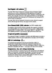
... connectors and supports the Intel® Matrix Storage Technology. Dual-channel memory support Employing the dual-channel DDR memory architecture, the motherboard provides a solution that features hyper-pipelined technology, and Extended Memory 64-bit Technology (EM64T). The ICH is a new generation server...performance. See page 2-13 for PCI-X 1.0a and other interfaces. 1.3 Special features 1.3.1 Product highlights Latest processor technology The motherboard comes with dual 604-pin surface mount ZIF sockets designed for the Intel® Xeon™ processor with lower pin count...
... connectors and supports the Intel® Matrix Storage Technology. Dual-channel memory support Employing the dual-channel DDR memory architecture, the motherboard provides a solution that features hyper-pipelined technology, and Extended Memory 64-bit Technology (EM64T). The ICH is a new generation server...performance. See page 2-13 for PCI-X 1.0a and other interfaces. 1.3 Special features 1.3.1 Product highlights Latest processor technology The motherboard comes with dual 604-pin surface mount ZIF sockets designed for the Intel® Xeon™ processor with lower pin count...
NCCH-DR User Manual English Version
Page 17
... to the dedicated CSA bus on the 64-bit PCI-X slot to a fast 480 Mbps on Motherboard (LOM) applications through the PCI bus. ASUS NCCH-DR 1-3 The ZCR capability provides a cost-effective, high-performance RAID sets. USB 2.0 technology The motherboard implements the Universal Serial Bus (USB) 2.0 specification, dramatically increasing the connection speed from the 12...
... to the dedicated CSA bus on the 64-bit PCI-X slot to a fast 480 Mbps on Motherboard (LOM) applications through the PCI bus. ASUS NCCH-DR 1-3 The ZCR capability provides a cost-effective, high-performance RAID sets. USB 2.0 technology The motherboard implements the Universal Serial Bus (USB) 2.0 specification, dramatically increasing the connection speed from the 12...
NCCH-DR User Manual English Version
Page 18
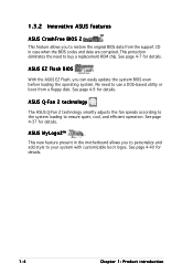
... 2 technology The ASUS Q-Fan 2 technology smartly adjusts the fan speeds according to the system loading to your system with customizable boot logos. This protection eliminates the need to use a DOS-based utility or boot from the support CD in the motherboard allows you to personalize ...and add style to ensure quiet, cool, and efficient operation. See page 4-7 for details. See page 4-40 for details. No need to buy a replacement ROM chip. See page 4-9 for details. 1-4 Chapter 1: Product introduction ASUS MyLogo2™ This...
... 2 technology The ASUS Q-Fan 2 technology smartly adjusts the fan speeds according to the system loading to your system with customizable boot logos. This protection eliminates the need to use a DOS-based utility or boot from the support CD in the motherboard allows you to personalize ...and add style to ensure quiet, cool, and efficient operation. See page 4-7 for details. See page 4-40 for details. No need to buy a replacement ROM chip. See page 4-9 for details. 1-4 Chapter 1: Product introduction ASUS MyLogo2™ This...

NCCH-DR User Manual English Version
Page 19
This chapter lists the hardware setup procedures that you have to perform when installing system components. It includes description of the jumpers and connectors on the motherboard. 2 Hardware information
This chapter lists the hardware setup procedures that you have to perform when installing system components. It includes description of the jumpers and connectors on the motherboard. 2 Hardware information

NCCH-DR User Manual English Version
Page 20
Chapter summary 2 2.1 Before you proceed 2-1 2.2 Motherboard overview 2-2 2.3 Central Processing Unit (CPU 2-13 2.4 System memory 2-16 2.5 Expansion slots 2-19 2.6. Jumpers 2-21 2.7 Connectors 2-26 ASUS NCCH-DR
Chapter summary 2 2.1 Before you proceed 2-1 2.2 Motherboard overview 2-2 2.3 Central Processing Unit (CPU 2-13 2.4 System memory 2-16 2.5 Expansion slots 2-19 2.6. Jumpers 2-21 2.7 Connectors 2-26 ASUS NCCH-DR

NCCH-DR User Manual English Version
Page 21
... is switched off mode. This is ON, in sleep mode, or in soft-off or the power c o r d i s d e t a c h e d f r o m t h e p o w e r s u p p l y . NCCH-DR NCCH-DR Onboard LED SB_PWR1 ON Standby Power OFF Powered Off ASUS NCCH-DR 2-1 The green LED lights up to the motherboard, peripherals, and/or components. The illustration below shows the location of the following precautions before you install...
... is switched off mode. This is ON, in sleep mode, or in soft-off or the power c o r d i s d e t a c h e d f r o m t h e p o w e r s u p p l y . NCCH-DR NCCH-DR Onboard LED SB_PWR1 ON Standby Power OFF Powered Off ASUS NCCH-DR 2-1 The green LED lights up to the motherboard, peripherals, and/or components. The illustration below shows the location of the following precautions before you install...

NCCH-DR User Manual English Version
Page 22
... chassis in the image below. 2.2.2 Screw holes Place nine (9) screws into the holes indicated by circles to secure the motherboard to the chassis. The edge with external ports goes to the rear part of the chassis 2-2 NCCH-DR Chapter 2: Hardware information Failure to unplug the chassis power cord before installing or removing the...
... chassis in the image below. 2.2.2 Screw holes Place nine (9) screws into the holes indicated by circles to secure the motherboard to the chassis. The edge with external ports goes to the rear part of the chassis 2-2 NCCH-DR Chapter 2: Hardware information Failure to unplug the chassis power cord before installing or removing the...

NCCH-DR User Manual English Version
Page 23
...in only one orientation. Determine the height of the standoffs on a stable surface, then locate the motherboard standoffs. Using the X-PAD accessory kit To install the support plates: 1. ASUS NCCH-DR 2-3 Standoff 2. Open and lay your system chassis on your chassis. Press the sheet flat making... sure that is completely pressed against to protect the motherboard. Use a nut size that it is slightly lower than...
...in only one orientation. Determine the height of the standoffs on a stable surface, then locate the motherboard standoffs. Using the X-PAD accessory kit To install the support plates: 1. ASUS NCCH-DR 2-3 Standoff 2. Open and lay your system chassis on your chassis. Press the sheet flat making... sure that is completely pressed against to protect the motherboard. Use a nut size that it is slightly lower than...

NCCH-DR User Manual English Version
Page 26
Heatsink hole matched to section "2.2.2 Screw holes" for illustration. 2-6 Chapter 2: Hardware information Install the motherboard with 9 screws. Refer to a nut on the support plate Make sure that the CPU heatsink holes on the motherboard perfectly match the metal nuts on top of the support plates. The support plates appear as shown when installed. 9. Secure the motherboard with the external I/O ports toward the chassis rear panel. The CPU sockets should be right on the support plates; otherwise, you can not install the CPU heatsinks properly. 10.
Heatsink hole matched to section "2.2.2 Screw holes" for illustration. 2-6 Chapter 2: Hardware information Install the motherboard with 9 screws. Refer to a nut on the support plate Make sure that the CPU heatsink holes on the motherboard perfectly match the metal nuts on top of the support plates. The support plates appear as shown when installed. 9. Secure the motherboard with the external I/O ports toward the chassis rear panel. The CPU sockets should be right on the support plates; otherwise, you can not install the CPU heatsinks properly. 10.

NCCH-DR User Manual English Version
Page 27
Locate the CPU heatsink holes on the motherboard. 2. CEK spring hook To install the CEK spring: 1. Press the upper spring hooks inward, then insert to the CPU1 heatsink holes. 3. Position the CEK spring underneath the motherboard, then match the CEK spring hooks to the upper CPU heatsink holes until they snap in place. ASUS NCCH-DR 2-7 Using the CEK springs Two CEK springs come with the motherboard package. Take note of the CPU heatsinks. You can also use these springs to support the weight of the four CEK spring hooks located beside the screw holes.
Locate the CPU heatsink holes on the motherboard. 2. CEK spring hook To install the CEK spring: 1. Press the upper spring hooks inward, then insert to the CPU1 heatsink holes. 3. Position the CEK spring underneath the motherboard, then match the CEK spring hooks to the upper CPU heatsink holes until they snap in place. ASUS NCCH-DR 2-7 Using the CEK springs Two CEK springs come with the motherboard package. Take note of the CPU heatsinks. You can also use these springs to support the weight of the four CEK spring hooks located beside the screw holes.

NCCH-DR User Manual English Version
Page 28
Repeat the process to install the second spring to the lower CPU heatsink holes until they snap in place. 5. Install the motherboard with 9 screws. The CPU sockets should be right on the CEK spring 7. Secure the motherboard with the external I/O ports toward the chassis rear panel. 4. The support plates appear as shown when installed. 6. Press the lower spring hooks inward, then insert to the CPU2 heatsink holes. Heatsink hole matched to section "2.2.2 Screw holes" for illustration. 2-8 Chapter 2: Hardware information Refer to the hole on top of the CEK springs.
Repeat the process to install the second spring to the lower CPU heatsink holes until they snap in place. 5. Install the motherboard with 9 screws. The CPU sockets should be right on the CEK spring 7. Secure the motherboard with the external I/O ports toward the chassis rear panel. 4. The support plates appear as shown when installed. 6. Press the lower spring hooks inward, then insert to the CPU2 heatsink holes. Heatsink hole matched to section "2.2.2 Screw holes" for illustration. 2-8 Chapter 2: Hardware information Refer to the hole on top of the CEK springs.

NCCH-DR User Manual English Version
Page 33
...Intel Xeon Gold Arrow CPU2 Pin A1 CPU1 NCCH-DR NCCH-DR CPU Socket 604 If installing only one CPU, use the socket CPU1. 2. 2.3 Central Processing Unit (CPU) The motherboard comes with 1 MB L2 cache. The sockets are designed for CPU1 ASUS NCCH-DR 2-13 Socket for the Intel® ...Xeon™ processor in completely. Locate the CPU sockets on the motherboard. The new generation Xeon™ processor supports ...
...Intel Xeon Gold Arrow CPU2 Pin A1 CPU1 NCCH-DR NCCH-DR CPU Socket 604 If installing only one CPU, use the socket CPU1. 2. 2.3 Central Processing Unit (CPU) The motherboard comes with 1 MB L2 cache. The sockets are designed for CPU1 ASUS NCCH-DR 2-13 Socket for the Intel® ...Xeon™ processor in completely. Locate the CPU sockets on the motherboard. The new generation Xeon™ processor supports ...

NCCH-DR User Manual English Version
Page 35
... the heatsink on top of the installed CPU, making sure that you have applied the thermal grease to install the second heatsink on this motherboard. Use a Phillips screwdriver to provide optimum thermal condition and performance. 2.3.2 Installing the CPU heatsink(s) The Intel® Xeon™ processors ...sequence. 3. To install the CPU heatsink and fan: 1. Repeat the process to the top of the second CPU, if any. ASUS NCCH-DR 2-15 Visit the ASUS website (www.asus.com) for an updated list of the CEK spring. 2. Make sure that the four screws on the heatsink align with the ...
... the heatsink on top of the installed CPU, making sure that you have applied the thermal grease to install the second heatsink on this motherboard. Use a Phillips screwdriver to provide optimum thermal condition and performance. 2.3.2 Installing the CPU heatsink(s) The Intel® Xeon™ processors ...sequence. 3. To install the CPU heatsink and fan: 1. Repeat the process to the top of the second CPU, if any. ASUS NCCH-DR 2-15 Visit the ASUS website (www.asus.com) for an updated list of the CEK spring. 2. Make sure that the four screws on the heatsink align with the ...

NCCH-DR User Manual English Version
Page 36
2.4 System memory 2.4.1 Overview The motherboard comes with the same CAS latency. The following figure illustrates the location of the recommended configurations in single-channel mode. 2-16 Chapter 2: Hardware information Refer to the DDR Qualified Vendors List on the the ASUS website for details. • In dual-...installed four 1 GB DDR memory modules. • Three DDR DIMMs installed into any of the DDR DIMM sockets: 104 Pins 80 Pins NCCH-DR NCCH-DR 184-Pin DDR DIMM sockets DIMM_A1 DIMM_A2 DIMM_B1 DIMM_B2 2.4.2 Memory configurations You may install 128 MB, 256 MB, 512 MB and 1 ...
2.4 System memory 2.4.1 Overview The motherboard comes with the same CAS latency. The following figure illustrates the location of the recommended configurations in single-channel mode. 2-16 Chapter 2: Hardware information Refer to the DDR Qualified Vendors List on the the ASUS website for details. • In dual-...installed four 1 GB DDR memory modules. • Three DDR DIMMs installed into any of the DDR DIMM sockets: 104 Pins 80 Pins NCCH-DR NCCH-DR 184-Pin DDR DIMM sockets DIMM_A1 DIMM_A2 DIMM_B1 DIMM_B2 2.4.2 Memory configurations You may install 128 MB, 256 MB, 512 MB and 1 ...


