NCCH-DR User Manual English Version
Page 17
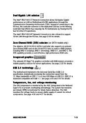
... Network Connection allows full-duplex Gigabit performance on LAN on Motherboard (LOM) applications through the PCI bus. Zero-Channel RAID (ZCR) solution (on SATA models only) The Adaptec AIC-8130 PCI-X SATA-II controller also supports an optional Zero-Channel RAID card on the 64-bit PCI-X slot to a fast 480 Mbps on the Memory Controller Hub (MCH) thus reducing the PCI bottlenecks by the ASIC (integrated in the Winbond Super I /O operations. ASUS NCCH-DR 1-3 Integrated graphics The onboard...
... Network Connection allows full-duplex Gigabit performance on LAN on Motherboard (LOM) applications through the PCI bus. Zero-Channel RAID (ZCR) solution (on SATA models only) The Adaptec AIC-8130 PCI-X SATA-II controller also supports an optional Zero-Channel RAID card on the 64-bit PCI-X slot to a fast 480 Mbps on the Memory Controller Hub (MCH) thus reducing the PCI bottlenecks by the ASIC (integrated in the Winbond Super I /O operations. ASUS NCCH-DR 1-3 Integrated graphics The onboard...
NCCH-DR User Manual English Version
Page 18
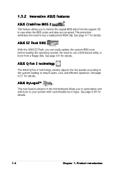
... protection eliminates the need to buy a replacement ROM chip. 1.3.2 Innovative ASUS features ASUS CrashFree BIOS 2 This feature allows you to restore the original BIOS data from a floppy disk. ASUS EZ Flash BIOS With the ASUS EZ Flash, you can easily update the system BIOS even before loading the operating system. No need to use a DOS-based utility or boot from the support CD in the motherboard allows you to personalize and add...
... protection eliminates the need to buy a replacement ROM chip. 1.3.2 Innovative ASUS features ASUS CrashFree BIOS 2 This feature allows you to restore the original BIOS data from a floppy disk. ASUS EZ Flash BIOS With the ASUS EZ Flash, you can easily update the system BIOS even before loading the operating system. No need to use a DOS-based utility or boot from the support CD in the motherboard allows you to personalize and add...
NCCH-DR User Manual English Version
Page 31
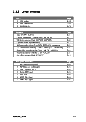
.../PCI-X slots Page 2-13 2-16 2-20 Jumpers Clear RTC RAM (CLRTC1) CPU fan pin selection (3-pin FM_CPU1, FM_CPU2) USB device wake-up (3-pin USBPW12, USBPW34) Keyboard power (3-pin KBPWR1) SATA controller setting (3-pin SATA_EN1) SATA models only SATA controller LED setting (3-pin 8130LED1) SATA models only Gigabit LAN controller setting (3-pin LAN_EN1; Serial (COM1) port 5. LAN1 (RJ-45) port 7. CPU sockets 2. LAN_EN2) Integrated graphics controller (3-pin VGA_EN1) Force BIOS recovery (3-pin RECOVERY) Page 2-21 2-22 2-22 2-23 2-23 2-24 2-24 2-25 2-25 Rear panel connectors 1. VGA port...
.../PCI-X slots Page 2-13 2-16 2-20 Jumpers Clear RTC RAM (CLRTC1) CPU fan pin selection (3-pin FM_CPU1, FM_CPU2) USB device wake-up (3-pin USBPW12, USBPW34) Keyboard power (3-pin KBPWR1) SATA controller setting (3-pin SATA_EN1) SATA models only SATA controller LED setting (3-pin 8130LED1) SATA models only Gigabit LAN controller setting (3-pin LAN_EN1; Serial (COM1) port 5. LAN1 (RJ-45) port 7. CPU sockets 2. LAN_EN2) Integrated graphics controller (3-pin VGA_EN1) Force BIOS recovery (3-pin RECOVERY) Page 2-21 2-22 2-22 2-23 2-23 2-24 2-24 2-25 2-25 Rear panel connectors 1. VGA port...

NCCH-DR User Manual English Version
Page 39
... power cord before adding or removing expansion cards. Secure the card to the chassis with the slot and press firmly until the card is already installed in a chassis). 3. See Chapter 4 for later use . ASUS NCCH-DR 2-19 Turn on the system and change the necessary BIOS settings, if any. 2.5 Expansion slots In the future, you may cause you physical injury and damage motherboard components. 2.5.1 Installing an expansion card To install an expansion card...
... power cord before adding or removing expansion cards. Secure the card to the chassis with the slot and press firmly until the card is already installed in a chassis). 3. See Chapter 4 for later use . ASUS NCCH-DR 2-19 Turn on the system and change the necessary BIOS settings, if any. 2.5 Expansion slots In the future, you may cause you physical injury and damage motherboard components. 2.5.1 Installing an expansion card To install an expansion card...
NCCH-DR User Manual English Version
Page 40
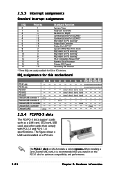
...* Floppy Disk Controller Printer Port (LPT1)* System CMOS/Real Time Clock IRQ holder for PCI steering* IRQ holder for PCI steering* IRQ holder for PCI steering* PS/2 Compatible Mouse Port* Numeric Data Processor Primary IDE Channel Secondary IDE Channel * These IRQs are usually available for this motherboard AB PCI-X1 slot -- shared shared shared shared shared shared shared shared shared shared shared shared shared shared shared 2.5.4 PCI/PCI-X slots The PCI/PCI-X slots support cards such as a LAN card...
...* Floppy Disk Controller Printer Port (LPT1)* System CMOS/Real Time Clock IRQ holder for PCI steering* IRQ holder for PCI steering* IRQ holder for PCI steering* PS/2 Compatible Mouse Port* Numeric Data Processor Primary IDE Channel Secondary IDE Channel * These IRQs are usually available for this motherboard AB PCI-X1 slot -- shared shared shared shared shared shared shared shared shared shared shared shared shared shared shared 2.5.4 PCI/PCI-X slots The PCI/PCI-X slots support cards such as a LAN card...
NCCH-DR User Manual English Version
Page 42
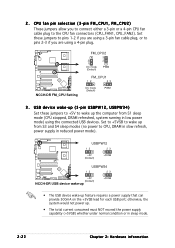
... power mode). USB device wake-up (3-pin USBPW12, USBPW34) Set these jumpers to pins 1-2 if you are using a 3-pin fan cable plug, or to pins 2-3 if you to connect either a 3-pin or a 4-pin CPU fan cable plug to CPU, DRAM in slow refresh, power supply in low power mode) using a 4-pin plug. 2 . USBPW12 12 23 +5V (Default) +5VSB USBPW34 12 23 NCCH-DR +5V (Default) NCCH-DR USB device wake-up +5VSB • The USB device wake-up the computer from S3 and S4 sleep modes (no power to the CPU fan connectors (CPU_FAN1, CPU_FAN2). NCCH-DR NCCH-DR FM_CPU Setting FM_CPU2...
... power mode). USB device wake-up (3-pin USBPW12, USBPW34) Set these jumpers to pins 1-2 if you are using a 3-pin fan cable plug, or to pins 2-3 if you to connect either a 3-pin or a 4-pin CPU fan cable plug to CPU, DRAM in slow refresh, power supply in low power mode) using a 4-pin plug. 2 . USBPW12 12 23 +5V (Default) +5VSB USBPW34 12 23 NCCH-DR +5V (Default) NCCH-DR USB device wake-up +5VSB • The USB device wake-up the computer from S3 and S4 sleep modes (no power to the CPU fan connectors (CPU_FAN1, CPU_FAN2). NCCH-DR NCCH-DR FM_CPU Setting FM_CPU2...

NCCH-DR User Manual English Version
Page 43
...to enable or disable the keyboard wake-up the computer when you to enable or disable the onboard Adaptec® AIC-8130 SATA RAID controller. NCCH-DR NCCH-DR SATA_EN setting SATA_EN1 3 2 2 1 Enable (Default) Disable ASUS NCCH-DR 2-23 Set to pins 1-2 to wake up feature. 4. KBPWR1 12 23 +5V (Default) +5VSB NCCH-DR NCCH-DR Keyboard power setting 5. Set this jumper to pins 2-3 (+5VSB) to activate the SATA controller. SATA controller setting (3-pin SATA_EN1) On SATA models only These jumpers allow you press a key on the +5VSB lead, and a corresponding setting in the BIOS...
...to enable or disable the keyboard wake-up the computer when you to enable or disable the onboard Adaptec® AIC-8130 SATA RAID controller. NCCH-DR NCCH-DR SATA_EN setting SATA_EN1 3 2 2 1 Enable (Default) Disable ASUS NCCH-DR 2-23 Set to pins 1-2 to wake up feature. 4. KBPWR1 12 23 +5V (Default) +5VSB NCCH-DR NCCH-DR Keyboard power setting 5. Set this jumper to pins 2-3 (+5VSB) to activate the SATA controller. SATA controller setting (3-pin SATA_EN1) On SATA models only These jumpers allow you press a key on the +5VSB lead, and a corresponding setting in the BIOS...

NCCH-DR User Manual English Version
Page 45
... motherboard (xxxx-xxx.BIN) and the AWDFLASH.EXE utility. 2. Shut down the system. 5. Force BIOS recovery (3-pin RECOVERY) This jumper allows you to update or recover the BIOS settings when it gets corrupted or destroyed.This jumper allows you enable or disable the onboard graphics controller. To update the BIOS: 1. Turn on the system to update/recover the BIOS quickly. NCCH-DR NCCH-DR VGA Setting VGA_EN1 12 23 Enable (Default) Disable 9 . Insert the floppy disk, then turn on the system. LED 0 LED1 RECOVERY PANEL1 RECOVERY...
... motherboard (xxxx-xxx.BIN) and the AWDFLASH.EXE utility. 2. Shut down the system. 5. Force BIOS recovery (3-pin RECOVERY) This jumper allows you to update or recover the BIOS settings when it gets corrupted or destroyed.This jumper allows you enable or disable the onboard graphics controller. To update the BIOS: 1. Turn on the system to update/recover the BIOS quickly. NCCH-DR NCCH-DR VGA Setting VGA_EN1 12 23 Enable (Default) Disable 9 . Insert the floppy disk, then turn on the system. LED 0 LED1 RECOVERY PANEL1 RECOVERY...

NCCH-DR User Manual English Version
Page 63
...S 2 (Updates the BIOS using the ASUS Update or Award BIOS Flash utilities. 4.1.1 Creating a bootable floppy disk 1. A S U S U p d a t e (Updates the BIOS in the future. Do either one of the original motherboard BIOS file to a bootable floppy disk in case you to the floppy disk drive. At the DOS prompt, type format A:/S then press . d. D O S s t a r t u p d i s k from the Windows® desktop, then select M y C o m p u t e r. A S U S E Z F l a s h (Updates the BIOS in DOS mode using a floppy disk or the motherboard support CD.) 4. Click S t a r t from the format options...
...S 2 (Updates the BIOS using the ASUS Update or Award BIOS Flash utilities. 4.1.1 Creating a bootable floppy disk 1. A S U S U p d a t e (Updates the BIOS in the future. Do either one of the original motherboard BIOS file to a bootable floppy disk in case you to the floppy disk drive. At the DOS prompt, type format A:/S then press . d. D O S s t a r t u p d i s k from the Windows® desktop, then select M y C o m p u t e r. A S U S E Z F l a s h (Updates the BIOS in DOS mode using a floppy disk or the motherboard support CD.) 4. Click S t a r t from the format options...

NCCH-DR User Manual English Version
Page 64
Insert a formatted, high density 1.44 MB floppy disk into the drive. In the O p e n field, type D:\bootdisk\makeboot a: assuming that D is your optical drive letter. Press , then follow screen instructions to the bootable floppy disk. 4-2 Chapter 4: BIOS setup c. Windows® 2000 environment To create a set of boot disks for Windows® 2000: a. Copy the original or the latest motherboard BIOS file to continue. 2. d. e. Insert the Windows® 2000 CD to the optical drive. b. Click S t a r t, then select R u n.
Insert a formatted, high density 1.44 MB floppy disk into the drive. In the O p e n field, type D:\bootdisk\makeboot a: assuming that D is your optical drive letter. Press , then follow screen instructions to the bootable floppy disk. 4-2 Chapter 4: BIOS setup c. Windows® 2000 environment To create a set of boot disks for Windows® 2000: a. Copy the original or the latest motherboard BIOS file to continue. 2. d. e. Insert the Windows® 2000 CD to the optical drive. b. Click S t a r t, then select R u n.
NCCH-DR User Manual English Version
Page 72
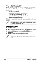
... drive. Installing ASUS Update To install ASUS Update: 1. ASUS Update requires an Internet connection either through a network or an Internet Service Provider (ISP). Click the U t i l i t i e s tab, then click I n s t a l l A S U S U p d a t e V X . The ASUS Update utility allows you to your system. Place the support CD in the support CD that allows you update the BIOS using this utility. 4-10 Chapter 4: BIOS setup Quit all Windows® applications before you to manage, save, and update the motherboard BIOS in Windows® environment. The ASUS Update utility...
... drive. Installing ASUS Update To install ASUS Update: 1. ASUS Update requires an Internet connection either through a network or an Internet Service Provider (ISP). Click the U t i l i t i e s tab, then click I n s t a l l A S U S U p d a t e V X . The ASUS Update utility allows you to your system. Place the support CD in the support CD that allows you update the BIOS using this utility. 4-10 Chapter 4: BIOS setup Quit all Windows® applications before you to manage, save, and update the motherboard BIOS in Windows® environment. The ASUS Update utility...
NCCH-DR User Manual English Version
Page 80
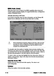
... Zone Sector PIO Mode UDMA Mode Transfer Mode S.M.A.R.T Status [Manual] [CHS] 0 MB [ 0] [ 0] [ 0] [ 0] [ 0] [Auto] [Auto] None None Select Menu Item Specific Help Selects the type of the hard disk cylinders. 4-18 Chapter 4: BIOS setup Incorrect settings may also highlight the item, then press to recognize the installed IDE drive! To enter a value, you may cause the system to fail to display a pop-up menu. Capacity [xxxxx MB] Displays the auto-detected hard disk capacity. Note...
... Zone Sector PIO Mode UDMA Mode Transfer Mode S.M.A.R.T Status [Manual] [CHS] 0 MB [ 0] [ 0] [ 0] [ 0] [ 0] [Auto] [Auto] None None Select Menu Item Specific Help Selects the type of the hard disk cylinders. 4-18 Chapter 4: BIOS setup Incorrect settings may also highlight the item, then press to recognize the installed IDE drive! To enter a value, you may cause the system to fail to display a pop-up menu. Capacity [xxxxx MB] Displays the auto-detected hard disk capacity. Note...

NCCH-DR User Manual English Version
Page 83
...after boot [Disabled] 19200 [Auto] [Disabled] Select Menu Item Specific Help Enabled - This item is user-configurable only when the C o n s o l e R e d i r e c t i o n option is set to select the agent address. Configuration options: [9600] [19200] [38400] [57600] [115200] Agent Address [Auto] This option allows you to display a pop-up . Attempt to [Enabled], the B a u d R a t e option is absent. when set the console redirection Baud rate. Configuration options: [Disabled] [Enabled] ASUS NCCH-DR 4-21 Attempt to redirect the console through the serial port. Console...
...after boot [Disabled] 19200 [Auto] [Disabled] Select Menu Item Specific Help Enabled - This item is user-configurable only when the C o n s o l e R e d i r e c t i o n option is set to select the agent address. Configuration options: [9600] [19200] [38400] [57600] [115200] Agent Address [Auto] This option allows you to display a pop-up . Attempt to [Enabled], the B a u d R a t e option is absent. when set the console redirection Baud rate. Configuration options: [Disabled] [Enabled] ASUS NCCH-DR 4-21 Attempt to redirect the console through the serial port. Console...
NCCH-DR User Manual English Version
Page 86
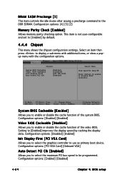
... the maximum PCI bus speed to be programmed. Configuration options: [4] [3] [2] Memory Parity Check [Enabled] Allows memory parity checking option. This item is not user-configurable and set to use as primary boot device. Select an item then press to the DDR SDRAM. DRAM RAS# Precharge [3] This item controls the idle clocks after issuing a precharge command to display a sub-menu with additional items, or show a popup menu with the configuration options. Configuration options: [PCI VGA Card] [Onboard VGA] Auto Detect PCI Clk [Enabled] Allows...
... the maximum PCI bus speed to be programmed. Configuration options: [4] [3] [2] Memory Parity Check [Enabled] Allows memory parity checking option. This item is not user-configurable and set to use as primary boot device. Select an item then press to the DDR SDRAM. DRAM RAS# Precharge [3] This item controls the idle clocks after issuing a precharge command to display a sub-menu with additional items, or show a popup menu with the configuration options. Configuration options: [PCI VGA Card] [Onboard VGA] Auto Detect PCI Clk [Enabled] Allows...
NCCH-DR User Manual English Version
Page 87
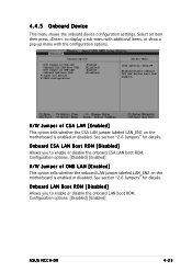
...] ASUS NCCH-DR 4-25 Select an item then press to enable or disable the onboard LAN boot ROM. Configuration options: [Disabled] [Enabled] H/W Jumper of CSA LAN [Enabled] This option tells whether the CSA LAN jumper labeled LAN_EN1 on the motherboard is enabled or disabled. See section "2.6 Jumpers" for details. Onboard Device H/W Jumper of CSA LAN Onboard CSA LAN Boot ROM H/W Jumper of ONB LAN Onboard LAN Boot ROM Super I/O Device SATA Configuration Enabled [Disabled] Enabled [Disabled] Select Menu Item Specific Help Enable/Disable Onboard CSA LAN device boot ROM support...
...] ASUS NCCH-DR 4-25 Select an item then press to enable or disable the onboard LAN boot ROM. Configuration options: [Disabled] [Enabled] H/W Jumper of CSA LAN [Enabled] This option tells whether the CSA LAN jumper labeled LAN_EN1 on the motherboard is enabled or disabled. See section "2.6 Jumpers" for details. Onboard Device H/W Jumper of CSA LAN Onboard CSA LAN Boot ROM H/W Jumper of ONB LAN Onboard LAN Boot ROM Super I/O Device SATA Configuration Enabled [Disabled] Enabled [Disabled] Select Menu Item Specific Help Enable/Disable Onboard CSA LAN device boot ROM support...
NCCH-DR User Manual English Version
Page 89
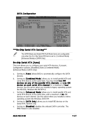
... IDE drives on each channel. Use ths option when you to install parallel ATA and serial ATA devices at the same time, with a maximum of f o u r devices. Setting to [A u t o] allows BIOS to [D i s a b l e d] disables the onboard SATA controller. Max. Setting to [C o m b i n e d M o d e] allows you installed a legacy operating system like Windows 2000/XP. SATA Configuration SATA Configuration *** On-Chip Serial ATA Setting *** On-Chip Serial ATA [Auto] SATA Mode IDE Serial ATA Port0 Mode SATA0 master Serial ATA Port1 Mode SATA1 master Select Menu Item Specific Help...
... IDE drives on each channel. Use ths option when you to install parallel ATA and serial ATA devices at the same time, with a maximum of f o u r devices. Setting to [A u t o] allows BIOS to [D i s a b l e d] disables the onboard SATA controller. Max. Setting to [C o m b i n e d M o d e] allows you installed a legacy operating system like Windows 2000/XP. SATA Configuration SATA Configuration *** On-Chip Serial ATA Setting *** On-Chip Serial ATA [Auto] SATA Mode IDE Serial ATA Port0 Mode SATA0 master Serial ATA Port1 Mode SATA1 master Select Menu Item Specific Help...

NCCH-DR User Manual English Version
Page 91
... enable or disabled resetting of all boot and Plug and Play devices. Reset Configuration Data [Disabled] Allows you to reset Extended System Configuration Data (ESCD) when you exit Setup, if you exit the Setup. PCI/VGA Pallete Snoop [Disabled] Some non-standard VGA cards, like graphics accelerators or MPEG video cards, may not show colors properly. Configuration options: [Auto] [3] [4] [5] [7] [9] [10] [11] [12] [14] [15] ASUS NCCH-DR 4-29 Refer to display a pop-up menu with other devices and cause system boot failure...
... enable or disabled resetting of all boot and Plug and Play devices. Reset Configuration Data [Disabled] Allows you to reset Extended System Configuration Data (ESCD) when you exit Setup, if you exit the Setup. PCI/VGA Pallete Snoop [Disabled] Some non-standard VGA cards, like graphics accelerators or MPEG video cards, may not show colors properly. Configuration options: [Auto] [3] [4] [5] [7] [9] [10] [11] [12] [14] [15] ASUS NCCH-DR 4-29 Refer to display a pop-up menu with other devices and cause system boot failure...
NCCH-DR User Manual English Version
Page 93
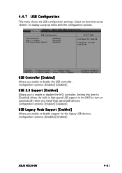
...in high speed USB support in the BIOS to display a pop-up menu with the configuration options. Configuration options: [Enabled] [Disabled] USB 2.0 Support [Enabled] Allows you enable or disable the USB controller. Configuration options: [Enabled] [Disabled] USB Legacy Mode Support [Enabled] Allows you install high speed USB devices. Configuration options: [Disabled] [Enabled] ASUS NCCH-DR 4-31 USB Configuration USB Controller USB 2.0 Support USB Legacy Mode Support [Enabled] [Enabled] [Enabled] Select Menu Item Specific Help Configures the USB controller. 4.4.7 USB Configuration This...
...in high speed USB support in the BIOS to display a pop-up menu with the configuration options. Configuration options: [Enabled] [Disabled] USB 2.0 Support [Enabled] Allows you enable or disable the USB controller. Configuration options: [Enabled] [Disabled] USB Legacy Mode Support [Enabled] Allows you install high speed USB devices. Configuration options: [Disabled] [Enabled] ASUS NCCH-DR 4-31 USB Configuration USB Controller USB 2.0 Support USB Legacy Mode Support [Enabled] [Enabled] [Enabled] Select Menu Item Specific Help Configures the USB controller. 4.4.7 USB Configuration This...
NCCH-DR User Manual English Version
Page 94
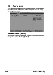
ACPI APIC Support [Enabled] Allows you to change the settings for Operating System. ACPI APIC Support APM Configuration Hardware Configuration [Enabled] Select Menu Item Specific Help Enable/Disable ACPI support for the Advanced Power Management (APM). Configuration options: [Disabled] [Enabled] 4-32 Chapter 4: BIOS setup 4.5 Power menu The Power menu items allow you to enable or disable the ACPI feature on the operating system. Select an item then press to display the configuration options.
ACPI APIC Support [Enabled] Allows you to change the settings for Operating System. ACPI APIC Support APM Configuration Hardware Configuration [Enabled] Select Menu Item Specific Help Enable/Disable ACPI support for the Advanced Power Management (APM). Configuration options: [Disabled] [Enabled] 4-32 Chapter 4: BIOS setup 4.5 Power menu The Power menu items allow you to enable or disable the ACPI feature on the operating system. Select an item then press to display the configuration options.
NCCH-DR User Manual English Version
Page 102
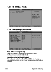
... Boot Settings Configuration Boot Other Device Quick Power On Self Test Halt On Case Open Warning Boot Up Floppy Seek Boot Up NumLock Status Typematic Rate Setting Typematic Rate (Chars/Sec) Typematic Delay (Msec) Full Screen LOGO Show [Enabled] [Enabled] [All Errors] [Enabled] [Enabled] [On] [Disabled] 6 250 [Enabled] Select Menu Item Specific Help Select your Boot Device Priority. Press to enable or disable selection of other boot device. Configuration options: [Disabled] [Enabled] 4-40 Chapter 4: BIOS setup 4.6.4 CD-ROM Boot Priority CD-ROM Boot Priority 1. 1st Slave : ASUS...
... Boot Settings Configuration Boot Other Device Quick Power On Self Test Halt On Case Open Warning Boot Up Floppy Seek Boot Up NumLock Status Typematic Rate Setting Typematic Rate (Chars/Sec) Typematic Delay (Msec) Full Screen LOGO Show [Enabled] [Enabled] [All Errors] [Enabled] [Enabled] [On] [Disabled] 6 250 [Enabled] Select Menu Item Specific Help Select your Boot Device Priority. Press to enable or disable selection of other boot device. Configuration options: [Disabled] [Enabled] 4-40 Chapter 4: BIOS setup 4.6.4 CD-ROM Boot Priority CD-ROM Boot Priority 1. 1st Slave : ASUS...


