N4L-VM DH User's Manual English Edition
Page 4
... the computer 3-2 3.2.1 Using the OS shut down function 3-2 3.2.2 Using the dual function power switch 3-2 Chapter 4: BIOS setup 4.1 Managing and updating your BIOS 4-1 4.1.1 ASUS Update utility 4-1 4.1.2 Creating a bootable floppy disk 4-4 4.1.3 ASUS EZ Flash utility 4-5 4.1.4 AFUDOS utility 4-6 4.1.5 ASUS CrashFree BIOS 2 utility 4-9 4.2 BIOS setup program 4-11 4.2.1 BIOS menu screen 4-12 4.2.2 Menu bar 4-12 4.2.3 Navigation keys 4-12 4.2.4 Menu items 4-13 4.2.5 Sub-menu...
... the computer 3-2 3.2.1 Using the OS shut down function 3-2 3.2.2 Using the dual function power switch 3-2 Chapter 4: BIOS setup 4.1 Managing and updating your BIOS 4-1 4.1.1 ASUS Update utility 4-1 4.1.2 Creating a bootable floppy disk 4-4 4.1.3 ASUS EZ Flash utility 4-5 4.1.4 AFUDOS utility 4-6 4.1.5 ASUS CrashFree BIOS 2 utility 4-9 4.2 BIOS setup program 4-11 4.2.1 BIOS menu screen 4-12 4.2.2 Menu bar 4-12 4.2.3 Navigation keys 4-12 4.2.4 Menu items 4-13 4.2.5 Sub-menu...
N4L-VM DH User's Manual English Edition
Page 9
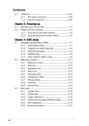
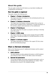
... 1: Product introduction This chapter describes the features of shutting down the system. • Chapter 4: BIOS setup This chapter tells how to change system settings through the BIOS Setup menus. These documents are also provided. • Chapter 5: Software support This chapter describes the... contents of the standard package. Detailed descriptions of the BIOS parameters are not part of the support CD that comes with the motherboard package. ASUS websites The ASUS website provides updated information on the motherboard. • Chapter 3: Powering up This...
... 1: Product introduction This chapter describes the features of shutting down the system. • Chapter 4: BIOS setup This chapter tells how to change system settings through the BIOS Setup menus. These documents are also provided. • Chapter 5: Software support This chapter describes the... contents of the standard package. Detailed descriptions of the BIOS parameters are not part of the support CD that comes with the motherboard package. ASUS websites The ASUS website provides updated information on the motherboard. • Chapter 3: Powering up This...
N4L-VM DH User's Manual English Edition
Page 12
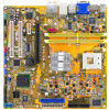
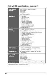
N4L-VM DH specifications summary ASUS Special features ASUS C.P.R. (CPU Parameter Recall) ASUS MyLogo ASUS Q-Fan ASUS EZ Flash ASUS CrashFree BIOS 2 Rear panel 1 x VGA port 1 x LAN (RJ-45) port 4 x USB 2.0 ports 1 x IEEE 1394a port 1 x External Serial ATA port 1 x Optical S/PDIF Out port 1 x ... 8 Mb Flash ROM, AMI BIOS, PnP, DMI, WfM2.0, ACPI 2.0a, SM BIOS 2.3 Manageability PXE, WOR by Ring, WOL/WOR by PME, WO USB, WO KB/MS Support CD contents Device drivers ASUS PC Probe II ASUS LiveUpdate Anti-Virus Utility Intervideo® WinDVD® Suite Form Factor uATX form factor: 9.6 ...
N4L-VM DH specifications summary ASUS Special features ASUS C.P.R. (CPU Parameter Recall) ASUS MyLogo ASUS Q-Fan ASUS EZ Flash ASUS CrashFree BIOS 2 Rear panel 1 x VGA port 1 x LAN (RJ-45) port 4 x USB 2.0 ports 1 x IEEE 1394a port 1 x External Serial ATA port 1 x Optical S/PDIF Out port 1 x ... 8 Mb Flash ROM, AMI BIOS, PnP, DMI, WfM2.0, ACPI 2.0a, SM BIOS 2.3 Manageability PXE, WOR by Ring, WOL/WOR by PME, WO USB, WO KB/MS Support CD contents Device drivers ASUS PC Probe II ASUS LiveUpdate Anti-Virus Utility Intervideo® WinDVD® Suite Form Factor uATX form factor: 9.6 ...
N4L-VM DH User's Manual English Edition
Page 16
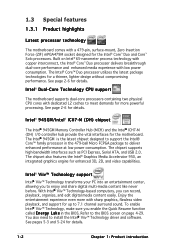
... 4-29. The Intel® 945GM is the latest chipset designed to support the Intel® Core™ family processor in the BIOS. The chipset also features the Intel® Graphics Media Accelerator 950, an integrated graphics engine for the Intel® Core™ Duo... without compromising performance. Intel® 945GM/Intel® ICH7-M (DH) chipset The Intel® 945GM Memory Controller Hub (MCH) and the Intel® ICH7-M (DH) I/O controller hub provide the vital interfaces for up to the BIOS screen on Intel® 65-nanometer process technology with copper interconnect,...
... 4-29. The Intel® 945GM is the latest chipset designed to support the Intel® Core™ family processor in the BIOS. The chipset also features the Intel® Graphics Media Accelerator 950, an integrated graphics engine for the Intel® Core™ Duo... without compromising performance. Intel® 945GM/Intel® ICH7-M (DH) chipset The Intel® 945GM Memory Controller Hub (MCH) and the Intel® ICH7-M (DH) I/O controller hub provide the vital interfaces for up to the BIOS screen on Intel® 65-nanometer process technology with copper interconnect,...
N4L-VM DH User's Manual English Edition
Page 19
...Command Queuing (NCQ), Power Management (PM) Implementation Algorithm, and Hot Swap. eliminates the need to overclocking, C.P.R. See page 5-9 for details. ASUS N4L-VM DH 1-5 This external port on the rear panel I/O provides smart setup, hot-plug and support for up to your system with lower pin count ... ATA products with port-multiplier functions. The Serial ATA 3 Gb/s specification provides twice the bandwidth of the motherboard BIOS allows automatic re-setting to the BIOS default settings in case the system hangs due to ensure quiet, cool, and efficient operation. See pages 2-25 ...
...Command Queuing (NCQ), Power Management (PM) Implementation Algorithm, and Hot Swap. eliminates the need to overclocking, C.P.R. See page 5-9 for details. ASUS N4L-VM DH 1-5 This external port on the rear panel I/O provides smart setup, hot-plug and support for up to your system with lower pin count ... ATA products with port-multiplier functions. The Serial ATA 3 Gb/s specification provides twice the bandwidth of the motherboard BIOS allows automatic re-setting to the BIOS default settings in case the system hangs due to ensure quiet, cool, and efficient operation. See pages 2-25 ...
N4L-VM DH User's Manual English Edition
Page 38
... to the card. Assign an IRQ to the chassis with the screw you removed earlier. 6. Make sure to do not need to the tables on BIOS setup. 2. Before installing the expansion card, read the documentation that you intend to the table on the next page for the card. 2. Turn on the... cards do so may need IRQ assignments. Remove the system unit cover (if your motherboard is completely seated on the system and change the necessary BIOS settings, if any.
... to the card. Assign an IRQ to the chassis with the screw you removed earlier. 6. Make sure to do not need to the tables on BIOS setup. 2. Before installing the expansion card, read the documentation that you intend to the table on the next page for the card. 2. Turn on the... cards do so may need IRQ assignments. Remove the system unit cover (if your motherboard is completely seated on the system and change the necessary BIOS settings, if any.
N4L-VM DH User's Manual English Edition
Page 41
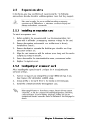
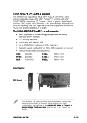
...1024x768 SXGA SXGA+ UXGA 1280x1024 1400x1050 1600x1200 Card layout DVI-D port You can adjust the output standard and other graphics configuration using the motherboard BIOS menu. The card supports dual screen display with DVI capability. The R-DVI-ADD2/R-DVI-ADD2-L card supports: • Intel® ... an onboard VGA (video graphics adapter), if available. Refer section "4.4.3 Chipset" for these configurations may be found in the A d v a n c e d M e n u > C h i p s e t > N o r t h B r i d g e C o n f i g u r a t i o n. The BIOS options for details. ASUS N4L-VM DH 2-19
...1024x768 SXGA SXGA+ UXGA 1280x1024 1400x1050 1600x1200 Card layout DVI-D port You can adjust the output standard and other graphics configuration using the motherboard BIOS menu. The card supports dual screen display with DVI capability. The R-DVI-ADD2/R-DVI-ADD2-L card supports: • Intel® ... an onboard VGA (video graphics adapter), if available. Refer section "4.4.3 Chipset" for these configurations may be found in the A d v a n c e d M e n u > C h i p s e t > N o r t h B r i d g e C o n f i g u r a t i o n. The BIOS options for details. ASUS N4L-VM DH 2-19

N4L-VM DH User's Manual English Edition
Page 43
... 1-2. 4. Reinstall the battery. 5. The onboard button cell battery powers the RAM data in CMOS. ASUS N4L-VM DH 2-21 2.6 Jumpers 1. N4L-VM DH ® N4L-VM DH Clear RTC RAM CLRTC 12 23 Normal (Default) Clear CMOS • Make sure to re-enter your previous BIOS settings after you to default values. Turn OFF the computer and unplug the power cord...
... 1-2. 4. Reinstall the battery. 5. The onboard button cell battery powers the RAM data in CMOS. ASUS N4L-VM DH 2-21 2.6 Jumpers 1. N4L-VM DH ® N4L-VM DH Clear RTC RAM CLRTC 12 23 Normal (Default) Clear CMOS • Make sure to re-enter your previous BIOS settings after you to default values. Turn OFF the computer and unplug the power cord...

N4L-VM DH User's Manual English Edition
Page 45
N4L-VM DH KBPWR 12 23 +5V (Default) +5VSB ® N4L-VM DH Keyboard power setting ASUS N4L-VM DH 2-23 This feature requires an ATX power supply that can supply at least 1A on the keyboard (the default is the Space Bar). Set this jumper to pins 2-3 (+5VSB) to enable or disable the PS/2 keyboard wake-up the computer when you press a key on the +5VSB lead, and a corresponding setting in the BIOS. Keyboard power (3-pin KBPWR) This jumper allows you to wake up feature. 3.
N4L-VM DH KBPWR 12 23 +5V (Default) +5VSB ® N4L-VM DH Keyboard power setting ASUS N4L-VM DH 2-23 This feature requires an ATX power supply that can supply at least 1A on the keyboard (the default is the Space Bar). Set this jumper to pins 2-3 (+5VSB) to enable or disable the PS/2 keyboard wake-up the computer when you press a key on the +5VSB lead, and a corresponding setting in the BIOS. Keyboard power (3-pin KBPWR) This jumper allows you to wake up feature. 3.

N4L-VM DH User's Manual English Edition
Page 49
N4L-VM DH IDE NOTE: Orient the red markings (usually zigzag) on how to set the C o n f i g u r e S A T A A s item in the BIOS to [RAID]. I n t e l® ICH7-M DH Southbridge Serial ATA connectors (7-pin SATA0 [black], SATA2 [black]) These connectors are for the Serial ATA ...I (1.5 Gb/s) hard disk and optical disk drives. GND RSATA_RXN2 RSATA_RXP2 GND RSATA_TXN2 RSATA_TXP2 GND N4L-VM DH ® N4L-VM DH SATA connectors SATA2 SATA0 GND RSATA_TXP1 RSATA_TXN1 GND RSATA_RXP1 RSATA_RXN1 GND ASUS N4L-VM DH 2-27 If you installed Serial ATA hard disk drives, you intend to create a Serial ATA ...
N4L-VM DH IDE NOTE: Orient the red markings (usually zigzag) on how to set the C o n f i g u r e S A T A A s item in the BIOS to [RAID]. I n t e l® ICH7-M DH Southbridge Serial ATA connectors (7-pin SATA0 [black], SATA2 [black]) These connectors are for the Serial ATA ...I (1.5 Gb/s) hard disk and optical disk drives. GND RSATA_RXN2 RSATA_RXP2 GND RSATA_TXN2 RSATA_TXP2 GND N4L-VM DH ® N4L-VM DH SATA connectors SATA2 SATA0 GND RSATA_TXP1 RSATA_TXN1 GND RSATA_RXP1 RSATA_RXN1 GND ASUS N4L-VM DH 2-27 If you installed Serial ATA hard disk drives, you intend to create a Serial ATA ...
N4L-VM DH User's Manual English Edition
Page 52
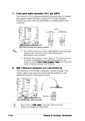
... Line out_R NC Line out_L PORT1 L PORT1 R PORT2 R SENSE_SEND PORT2 L N4L-VM DH ® N4L-VM DH Analog front panel connector • We recommend that supports either HD Audio or legacy AC '97 audio standard. N4L-VM DH +12V TPB1+ GND TPA1+ 1 ® IE1394_2 N4L-VM DH IEEE 1394 connector GND +12V TPB1GND TPA1- Never connect a U S B...This connector is set the F r o n t P a n e l S u p p o r t T y p e item in the BIOS setup to the IEEE 1394a connectors. See page 4-24 for the IEEE 1394a port. Doing so will damage the motherboard! 2-30 Chapter 2: Hardware information
... Line out_R NC Line out_L PORT1 L PORT1 R PORT2 R SENSE_SEND PORT2 L N4L-VM DH ® N4L-VM DH Analog front panel connector • We recommend that supports either HD Audio or legacy AC '97 audio standard. N4L-VM DH +12V TPB1+ GND TPA1+ 1 ® IE1394_2 N4L-VM DH IEEE 1394 connector GND +12V TPB1GND TPA1- Never connect a U S B...This connector is set the F r o n t P a n e l S u p p o r t T y p e item in the BIOS setup to the IEEE 1394a connectors. See page 4-24 for the IEEE 1394a port. Doing so will damage the motherboard! 2-30 Chapter 2: Hardware information
N4L-VM DH User's Manual English Edition
Page 58
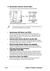
PWR Ground Reset Ground IDE_LED RESET ® PWR N4L-VM DH System panel connector * Requires an ATX power supply. Connect the chassis power LED cable to the connector description below for details. • System power LED (... sleep or soft-off button (Light Green 2-pin PWR) This connector is for the system power button. 17. The speaker allows you turn on the BIOS settings. The IDE LED lights up when you to this connector. PLED SPEAKER PLED+ PLED+5V Ground Ground Speaker N4L-VM DH PANEL IDE_LED+ IDE_LED-
PWR Ground Reset Ground IDE_LED RESET ® PWR N4L-VM DH System panel connector * Requires an ATX power supply. Connect the chassis power LED cable to the connector description below for details. • System power LED (... sleep or soft-off button (Light Green 2-pin PWR) This connector is for the system power button. 17. The speaker allows you turn on the BIOS settings. The IDE LED lights up when you to this connector. PLED SPEAKER PLED+ PLED+5V Ground Ground Speaker N4L-VM DH PANEL IDE_LED+ IDE_LED-

N4L-VM DH User's Manual English Edition
Page 61
...screen. System power 6. Be sure that is equipped with the last device on . While the tests are off. 3. Connect the power cord to enter the BIOS Setup. Monitor b. For systems with "green" standards or if it has a "power standby" feature, the monitor LED may have failed a power-on ... the time you press the ATX power button. The system then runs the power-on test. If your retailer for the first time 1. ASUS PN4L-VM DH 3-1 Connect the power cord to a power outlet that all the connections, replace the system case cover. 2. After making all switches are running,...
...screen. System power 6. Be sure that is equipped with the last device on . While the tests are off. 3. Connect the power cord to enter the BIOS Setup. Monitor b. For systems with "green" standards or if it has a "power standby" feature, the monitor LED may have failed a power-on ... the time you press the ATX power button. The system then runs the power-on test. If your retailer for the first time 1. ASUS PN4L-VM DH 3-1 Connect the power cord to a power outlet that all the connections, replace the system case cover. 2. After making all switches are running,...
N4L-VM DH User's Manual English Edition
Page 62
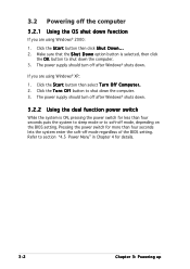
... sleep mode or to section "4.5 Power Menu" in Chapter 4 for less than four seconds lets the system enter the soft-off mode regardless of the BIOS setting. Make sure that the S h u t D o w n option button is ON, pressing the power switch for details. 3-2 Chapter 3: Powering up If you are... using Windows® 2000: 1. Refer to soft-off mode, depending on the BIOS setting. 3.2 Powering off the computer 3.2.1 Using the OS shut down function If you are using Windows® XP: 1. The power supply should turn ...
... sleep mode or to section "4.5 Power Menu" in Chapter 4 for less than four seconds lets the system enter the soft-off mode regardless of the BIOS setting. Make sure that the S h u t D o w n option button is ON, pressing the power switch for details. 3-2 Chapter 3: Powering up If you are... using Windows® 2000: 1. Refer to soft-off mode, depending on the BIOS setting. 3.2 Powering off the computer 3.2.1 Using the OS shut down function If you are using Windows® XP: 1. The power supply should turn ...
N4L-VM DH User's Manual English Edition
Page 63
This chapter tells how to change the system settings through the BIOS Setup menus. Detailed descriptions of the BIOS parameters are also provided. 4 BIOS setup
This chapter tells how to change the system settings through the BIOS Setup menus. Detailed descriptions of the BIOS parameters are also provided. 4 BIOS setup

N4L-VM DH User's Manual English Edition
Page 64
Chapter summary 4 4.1 Managing and updating your BIOS 4-1 4.2 BIOS setup program 4-11 4.3 Main menu 4-14 4.4 Advanced menu 4-18 4.5 Power menu 4-29 4.6 Boot menu 4-34 4.7 Exit menu 4-38 ASUS N4L-VM DH
Chapter summary 4 4.1 Managing and updating your BIOS 4-1 4.2 BIOS setup program 4-11 4.3 Main menu 4-14 4.4 Advanced menu 4-18 4.5 Power menu 4-29 4.6 Boot menu 4-34 4.7 Exit menu 4-38 ASUS N4L-VM DH
N4L-VM DH User's Manual English Edition
Page 65
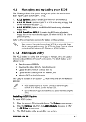
... allows you to the corresponding sections for the U t i l i t i e s screen menu. 3. See page 5-3 for details on these utilities. A S U S U p d a t e (Updates the BIOS in the optical drive. Place the support CD in Windows® environment.) 2. ASUS N4L-VM DH 4-1 A S U S A F U D O S (Updates the BIOS in DOS mode using a floppy disk or the motherboard support CD.) 3. Save a copy of the original motherboard...
... allows you to the corresponding sections for the U t i l i t i e s screen menu. 3. See page 5-3 for details on these utilities. A S U S U p d a t e (Updates the BIOS in the optical drive. Place the support CD in Windows® environment.) 2. ASUS N4L-VM DH 4-1 A S U S A F U D O S (Updates the BIOS in DOS mode using a floppy disk or the motherboard support CD.) 3. Save a copy of the original motherboard...
N4L-VM DH User's Manual English Edition
Page 66
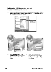
N e x t. The ASUS Update main window appears. 2. Updating the BIOS through the Internet To update the BIOS through the Internet: 1. Click N e x t. 4-2 Chapter 4: BIOS setup Select U p d a t e B I n t e r n e t option from the Windows® desktop by clicking S t a r t > P r o g r a m s > A S U S > A S U S U p d a t e > A S U S U p d a t e. Select the ASUS FTP site t h e I O S f r o m 3. Launch the ASUS Update utility from the nearest you to avoid network drop-down menu, then click traffic, or click A u t o S e l e c t.
N e x t. The ASUS Update main window appears. 2. Updating the BIOS through the Internet To update the BIOS through the Internet: 1. Click N e x t. 4-2 Chapter 4: BIOS setup Select U p d a t e B I n t e r n e t option from the Windows® desktop by clicking S t a r t > P r o g r a m s > A S U S > A S U S U p d a t e > A S U S U p d a t e. Select the ASUS FTP site t h e I O S f r o m 3. Launch the ASUS Update utility from the nearest you to avoid network drop-down menu, then click traffic, or click A u t o S e l e c t.

N4L-VM DH User's Manual English Edition
Page 67
... screen instructions to complete the update process. The ASUS Update main window appears. 2. ASUS N4L-VM DH 4-3 Locate the BIOS file from the Windows® desktop by clicking S t a r t > P r o g r a m s > A S U S > A S U S U p d a t e > A S U S U p d a t e. Follow the screen instructions to complete the update process. The ASUS Update utility is capable of updating itself through a BIOS file: 1. Launch the ASUS Update utility from the O p e n window, then click...
... screen instructions to complete the update process. The ASUS Update main window appears. 2. ASUS N4L-VM DH 4-3 Locate the BIOS file from the Windows® desktop by clicking S t a r t > P r o g r a m s > A S U S > A S U S U p d a t e > A S U S U p d a t e. Follow the screen instructions to complete the update process. The ASUS Update utility is capable of updating itself through a BIOS file: 1. Launch the ASUS Update utility from the O p e n window, then click...
N4L-VM DH User's Manual English Edition
Page 68
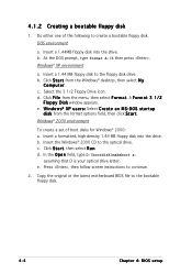
.... c. d. e. Windows® 2000 environment To create a set of the following to create a bootable floppy disk. Copy the original or the latest motherboard BIOS file to continue. 2. Do either one of boot disks for Windows® 2000: a. W i n d o w s® X P u s ... e a t e a n M S - Click S t a r t, then select R u n. Press , then follow screen instructions to the bootable floppy disk. 4-4 Chapter 4: BIOS setup Insert a 1.44MB floppy disk into the drive. Insert the Windows® 2000 CD to the floppy disk drive. b. DOS environment a. D O S s t a r t u...
.... c. d. e. Windows® 2000 environment To create a set of the following to create a bootable floppy disk. Copy the original or the latest motherboard BIOS file to continue. 2. Do either one of boot disks for Windows® 2000: a. W i n d o w s® X P u s ... e a t e a n M S - Click S t a r t, then select R u n. Press , then follow screen instructions to the bootable floppy disk. 4-4 Chapter 4: BIOS setup Insert a 1.44MB floppy disk into the drive. Insert the Windows® 2000 CD to the floppy disk drive. b. DOS environment a. D O S s t a r t u...


