
User Guide
Page 1
M4N75TD Motherboard
M4N75TD Motherboard

User Guide
Page 3
Contents Contents...iii Notices...vi Safety information vii About this guide vii M4N75TD specifications summary ix Chapter 1 Product introduction 1.1 Welcome 1-1 1.2 Package contents 1-1 1.3 Special features 1-1 1.3.1 Product highlights 1-1 1.3.2 ASUS Unique Features 1-2 1.4 Before you proceed 1-4 1.5 Motherboard overview 1-4 1.5.1 Placement direction 1-4 1.5.2 Screw holes 1-4 1.5.3 Motherboard layout 1-5 1.5.4 Layout contents 1-5 1.6 Central Processing Unit (CPU 1-6 1.6.1 Installing the CPU 1-6 1.6.2 Installing the heatsink and fan 1-7 1.7 System...
Contents Contents...iii Notices...vi Safety information vii About this guide vii M4N75TD specifications summary ix Chapter 1 Product introduction 1.1 Welcome 1-1 1.2 Package contents 1-1 1.3 Special features 1-1 1.3.1 Product highlights 1-1 1.3.2 ASUS Unique Features 1-2 1.4 Before you proceed 1-4 1.5 Motherboard overview 1-4 1.5.1 Placement direction 1-4 1.5.2 Screw holes 1-4 1.5.3 Motherboard layout 1-5 1.5.4 Layout contents 1-5 1.6 Central Processing Unit (CPU 1-6 1.6.1 Installing the CPU 1-6 1.6.2 Installing the heatsink and fan 1-7 1.7 System...

User Guide
Page 6
...digital device, pursuant to Part 15 of Chemicals) regulatory framework, we published the chemical substances in our products at ASUS REACH website at http://green.asus.com/english/REACH.htm. Changes or modifications to this equipment. REACH Complying with the REACH (Registration, Evaluation, Authorisation..., and Restriction of the FCC Rules. DO NOT throw the motherboard in municipal waste. This equipment generates, uses...
...digital device, pursuant to Part 15 of Chemicals) regulatory framework, we published the chemical substances in our products at ASUS REACH website at http://green.asus.com/english/REACH.htm. Changes or modifications to this equipment. REACH Complying with the REACH (Registration, Evaluation, Authorisation..., and Restriction of the FCC Rules. DO NOT throw the motherboard in municipal waste. This equipment generates, uses...

User Guide
Page 7
... This chapter describes the features of the BIOS parameters are also provided. Detailed descriptions of the motherboard and the new technology it by yourself. Operation safety • Before installing the motherboard and adding devices on a stable surface. • If you encounter technical problems with the ...are using, contact your dealer immediately. • To avoid short circuits, keep paper clips, screws, and staples away from the motherboard, ensure that the power cables for the devices are unplugged before the signal cables are connected. About this guide is broken, do...
... This chapter describes the features of the BIOS parameters are also provided. Detailed descriptions of the motherboard and the new technology it by yourself. Operation safety • Before installing the motherboard and adding devices on a stable surface. • If you encounter technical problems with the ...are using, contact your dealer immediately. • To avoid short circuits, keep paper clips, screws, and staples away from the motherboard, ensure that the power cables for the devices are unplugged before the signal cables are connected. About this guide is broken, do...

User Guide
Page 13
... damaged or missing, contact your package with less power consumption. Before you for the following items. Motherboard Cables Accessories Application DVD Documentations ASUS M4N75TD motherboard 1 x Ultra DMA 133/100/66 cable 2 x Serial ATA cables 1 x SLI bridge cable 1 x I/O shield ASUS motherboard support DVD User manual If any of new features and latest technologies, making it , check the...
... damaged or missing, contact your package with less power consumption. Before you for the following items. Motherboard Cables Accessories Application DVD Documentations ASUS M4N75TD motherboard 1 x Ultra DMA 133/100/66 cable 2 x Serial ATA cables 1 x SLI bridge cable 1 x I/O shield ASUS motherboard support DVD User manual If any of new features and latest technologies, making it , check the...

User Guide
Page 14
...3 Gb/s devices, PCI Express x16 slots with just a simple switch or hot key. ASUS Power Solutions 8+1 Phase Power Design To fully unleash the latest generation AM3 CPU's potential, ASUS M4N75TD motherboard has adopted the brand-new 8-phase VRM power design, which provides faster data transfer rate and...® Scalable Link Interface (SLI) technology that allows two graphics processing units (GPUs) in no more bandwidth to vital components. 1-2 ASUS M4N75TD MemOK! This remarkable memory rescue tool requires nothing but a push of a latent AMD® CPU-with NVIDIA® SLI™ ...
...3 Gb/s devices, PCI Express x16 slots with just a simple switch or hot key. ASUS Power Solutions 8+1 Phase Power Design To fully unleash the latest generation AM3 CPU's potential, ASUS M4N75TD motherboard has adopted the brand-new 8-phase VRM power design, which provides faster data transfer rate and...® Scalable Link Interface (SLI) technology that allows two graphics processing units (GPUs) in no more bandwidth to vital components. 1-2 ASUS M4N75TD MemOK! This remarkable memory rescue tool requires nothing but a push of a latent AMD® CPU-with NVIDIA® SLI™ ...

User Guide
Page 15
... (printed circuit board) for effective heat dissipation-making temperatures cooler by ASUS. settings in TurboV provides the best O.C. Not only the beautifully curved fins upgrade the visual enjoyment for motherboard users, but also the special thickened bottom design effectively cools down hot...Chapter 1: Product introduction 1-3 tool allows you to overclock without interrupting ongoing work or games, simply through pressing the button. More, the ASUS OC Profiles in different scenarios. Up to 20ºC (36ºF) Cooler-Stack Cool 3 Stack Cool 3 is a fanless cooling solution...
... (printed circuit board) for effective heat dissipation-making temperatures cooler by ASUS. settings in TurboV provides the best O.C. Not only the beautifully curved fins upgrade the visual enjoyment for motherboard users, but also the special thickened bottom design effectively cools down hot...Chapter 1: Product introduction 1-3 tool allows you to overclock without interrupting ongoing work or games, simply through pressing the button. More, the ASUS OC Profiles in different scenarios. Up to 20ºC (36ºF) Cooler-Stack Cool 3 Stack Cool 3 is a fanless cooling solution...

User Guide
Page 16
... or touch a safely grounded object or a metal object, such as indicated in the correct orientation. Failure to do so may cause severe damage to the motherboard, peripherals, or components. 1.5 Motherboard overview 1.5.1 Placement direction When installing the motherboard, ensure that came with external ports goes to the rear part of the chassis. 1-4 ASUS M4N75TD
... or touch a safely grounded object or a metal object, such as indicated in the correct orientation. Failure to do so may cause severe damage to the motherboard, peripherals, or components. 1.5 Motherboard overview 1.5.1 Placement direction When installing the motherboard, ensure that came with external ports goes to the rear part of the chassis. 1-4 ASUS M4N75TD
User Guide
Page 17
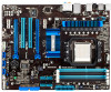
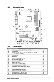
...) 13. Digital audio connector (4-1 pin SPDIF_OUT) 17. Clear RTC RAM (CLRTC) 10. Serial port connector (10-1 pin COM1) 14. CPU overvoltage setting (3-1 pin OV_CPU) 12. 1.5.3 Motherboard layout 1.5.4 Layout contents Connectors/Jumpers/Slots 1. Front panel audio connector (10-1 pin AAFP) Chapter 1: Product introduction Page 1-24 1-6 1-26 1-9 1-18 1-25 1-23 1-19 1-16 1-27...
...) 13. Digital audio connector (4-1 pin SPDIF_OUT) 17. Clear RTC RAM (CLRTC) 10. Serial port connector (10-1 pin COM1) 14. CPU overvoltage setting (3-1 pin OV_CPU) 12. 1.5.3 Motherboard layout 1.5.4 Layout contents Connectors/Jumpers/Slots 1. Front panel audio connector (10-1 pin AAFP) Chapter 1: Product introduction Page 1-24 1-6 1-26 1-9 1-18 1-25 1-23 1-19 1-16 1-27...
User Guide
Page 18
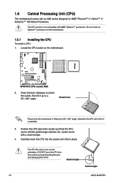
...; Phenom™ II / Athlon™ II / Sempron™ 100 Series Processors. 1.6 Central Processing Unit (CPU) The motherboard comes with AMD® Opteron™ processors. Small triangle Gold triangle 1-6 ASUS M4N75TD Locate the CPU socket on this motherboard. 1.6.1 Installing the CPU To install a CPU: 1. Carefully insert the CPU into the socket to a 90°-100...
...; Phenom™ II / Athlon™ II / Sempron™ 100 Series Processors. 1.6 Central Processing Unit (CPU) The motherboard comes with AMD® Opteron™ processors. Small triangle Gold triangle 1-6 ASUS M4N75TD Locate the CPU socket on this motherboard. 1.6.1 Installing the CPU To install a CPU: 1. Carefully insert the CPU into the socket to a 90°-100...

User Guide
Page 19
... the installed CPU, making sure that the heatsink fits properly on the retention module base. • The retention module base is already installed on the motherboard. To install the CPU heatsink and fan: 1. The lever clicks on the side tab to the CPU heatsink or CPU before you fail to the... purchase. • You do not have to remove the retention module base when installing the CPU or installing other motherboard components. • If you use only AMD-certified heatsink and fan assembly. You can occur if you install the heatsink and fan assembly. When the ...
... the installed CPU, making sure that the heatsink fits properly on the retention module base. • The retention module base is already installed on the motherboard. To install the CPU heatsink and fan: 1. The lever clicks on the side tab to the CPU heatsink or CPU before you fail to the... purchase. • You do not have to remove the retention module base when installing the CPU or installing other motherboard components. • If you use only AMD-certified heatsink and fan assembly. You can occur if you install the heatsink and fan assembly. When the ...

User Guide
Page 20
... heatsink and fan to the retention module base. 1 2 3 4 5 3. Push down the retention bracket lock on the motherboard labeled CPU_FAN. Hardware monitoring errors can occur if you cannot snap the retention bracket in this connector. 1-8 ASUS M4N75TD Do not forget to plug this section do not match the CPU documentation, follow the latter. 2. Align...
... heatsink and fan to the retention module base. 1 2 3 4 5 3. Push down the retention bracket lock on the motherboard labeled CPU_FAN. Hardware monitoring errors can occur if you cannot snap the retention bracket in this connector. 1-8 ASUS M4N75TD Do not forget to plug this section do not match the CPU documentation, follow the latter. 2. Align...

User Guide
Page 21
... you install a 64-bit Windows OS when having 4GB or more memory on a DDR2 DIMM socket. 1.7 System memory 1.7.1 Overview The motherboard comes with the same CAS latency. Chapter 1: Product introduction 1-9 Any excess memory from a memory module. The figure illustrates the location of... accessing information from the higher-sized channel is dependent on the motherboard. • This motherboard does not support DIMMs made up of memory, we recommend that you install 4GB or more memory installed on its Serial...
... you install a 64-bit Windows OS when having 4GB or more memory on a DDR2 DIMM socket. 1.7 System memory 1.7.1 Overview The motherboard comes with the same CAS latency. Chapter 1: Product introduction 1-9 Any excess memory from a memory module. The figure illustrates the location of... accessing information from the higher-sized channel is dependent on the motherboard. • This motherboard does not support DIMMs made up of memory, we recommend that you install 4GB or more memory installed on its Serial...

User Guide
Page 26
.... DO NOT force a DIMM into the socket VERTICALLY to both the motherboard and the components. 1. Hold the DIMM by pressing the retaining clip outward. 2. Apply force to prevent DIMM notch damage. 1.7.4 Removing a DIMM 1. Remove the DIMM from the socket. 2 1 1-14 ASUS M4N75TD Align a DIMM on the socket such that it fits in the...
.... DO NOT force a DIMM into the socket VERTICALLY to both the motherboard and the components. 1. Hold the DIMM by pressing the retaining clip outward. 2. Apply force to prevent DIMM notch damage. 1.7.4 Removing a DIMM 1. Remove the DIMM from the socket. 2 1 1-14 ASUS M4N75TD Align a DIMM on the socket such that it fits in the...

User Guide
Page 27
...cards on shared slots, ensure that the drivers support "Share IRQ" or that the cards do so may cause you physical injury and damage motherboard components. 1.8.1 Installing an expansion card To install an expansion card: 1. Before installing the expansion card, read the documentation that you intend ... as a LAN card, SCSI card, USB card, and other cards that comply with PCI specifications. 1.8.4 PCI Express 2.0 x1 slots This motherboard supports PCI Express x1 network cards, SCSI cards, and other cards that comply with the PCI Express specifications. 1.8.5 PCI Express 2.0 x16 slots This...
...cards on shared slots, ensure that the drivers support "Share IRQ" or that the cards do so may cause you physical injury and damage motherboard components. 1.8.1 Installing an expansion card To install an expansion card: 1. Before installing the expansion card, read the documentation that you intend ... as a LAN card, SCSI card, USB card, and other cards that comply with PCI specifications. 1.8.4 PCI Express 2.0 x1 slots This motherboard supports PCI Express x1 network cards, SCSI cards, and other cards that comply with the PCI Express specifications. 1.8.5 PCI Express 2.0 x16 slots This...

User Guide
Page 30
...overclockers and gamers who continually change settings to enhance system performance. 1. Replace the DIMMs with the motherboard may cause system boot failure, and the DRAM_LED near the MemOK! function. 1-18 ASUS M4N75TD switch Installing DIMMs that you download and update to the latest BIOS version from the... ASUS website at www.asus.com. • If you to fine-tune performance when working on the computer....
...overclockers and gamers who continually change settings to enhance system performance. 1. Replace the DIMMs with the motherboard may cause system boot failure, and the DRAM_LED near the MemOK! function. 1-18 ASUS M4N75TD switch Installing DIMMs that you download and update to the latest BIOS version from the... ASUS website at www.asus.com. • If you to fine-tune performance when working on the computer....

User Guide
Page 31
... in soft‑off . • The UNCLOCKER_LED near the Core Unlocker switch lights when the switch setting is ON, in sleep mode, or in any motherboard component. The green LED lights up to Enable when the system is powered off mode. 2. Refer to section 1.11 Onboard LEDs for the exact location... setting you to Enable. This is a reminder that the system is turned to unlock the extra cores of the onboard LED. Standby Power LED The motherboard comes with a standby power LED.
... in soft‑off . • The UNCLOCKER_LED near the Core Unlocker switch lights when the switch setting is ON, in sleep mode, or in any motherboard component. The green LED lights up to Enable when the system is powered off mode. 2. Refer to section 1.11 Onboard LEDs for the exact location... setting you to Enable. This is a reminder that the system is turned to unlock the extra cores of the onboard LED. Standby Power LED The motherboard comes with a standby power LED.

User Guide
Page 32
This user-friendly design provides an intuitional way to Enable. 1-20 ASUS M4N75TD Core Unlocker LED The Core Unlocker LED lights when the Core Unclocker switch is solved. DRAM LED DRAM LED checks the DRAM in sequence during motherboard booting process. If an error is found , the LED next to the error device will continue lighting until the problem is turned to locate the root problem within a second. 3. 2.
This user-friendly design provides an intuitional way to Enable. 1-20 ASUS M4N75TD Core Unlocker LED The Core Unlocker LED lights when the Core Unclocker switch is solved. DRAM LED DRAM LED checks the DRAM in sequence during motherboard booting process. If an error is found , the LED next to the error device will continue lighting until the problem is turned to locate the root problem within a second. 3. 2.

User Guide
Page 35
Connect the blue connector to the motherboard's IDE connector, then select one of the following modes to match the covered hole on each Ultra DMA 133 / 100 / 66 signal cable: blue, black, ...
Connect the blue connector to the motherboard's IDE connector, then select one of the following modes to match the covered hole on each Ultra DMA 133 / 100 / 66 signal cable: blue, black, ...

User Guide
Page 37
... to install the AHCI driver or RAID driver in the bundled support DVD before using these connectors, set the SATA Mode select item in the motherboard support DVD. Chapter 1: Product introduction 1-25 The data transfer rate of SATA ports to RAID mode, all SATA ports run at RAID mode together. •...
... to install the AHCI driver or RAID driver in the bundled support DVD before using these connectors, set the SATA Mode select item in the motherboard support DVD. Chapter 1: Product introduction 1-25 The data transfer rate of SATA ports to RAID mode, all SATA ports run at RAID mode together. •...


