
User Manual
Page 1
Motherboard M4A78-VM IN/SI
Motherboard M4A78-VM IN/SI
User Manual
Page 3
Contents Notices...v Safety information vi About this guide vi M4A78-VM IN/SI specifications summary viii Chapter 1: Product introduction 1.1 Before you proceed 1-1 1.2 Motherboard overview 1-2 1.2.1 Motherboard layout 1-2 1.2.2 Layout contents 1-2 1.3 Central ...17 1.8.2 Support DVD information 1-17 Chapter 2: BIOS information 2.1 Managing and updating your BIOS 2-1 2.1.1 ASUS Update utility 2-1 2.1.2 ASUS EZ Flash 2 utility 2-2 2.1.3 ASUS CrashFree BIOS 3 utility 2-2 2.2 BIOS setup program 2-3 2.3 Main menu 2-4 2.3.1 System Time 2-4 2.3.2 System Date 2-4 iii
Contents Notices...v Safety information vi About this guide vi M4A78-VM IN/SI specifications summary viii Chapter 1: Product introduction 1.1 Before you proceed 1-1 1.2 Motherboard overview 1-2 1.2.1 Motherboard layout 1-2 1.2.2 Layout contents 1-2 1.3 Central ...17 1.8.2 Support DVD information 1-17 Chapter 2: BIOS information 2.1 Managing and updating your BIOS 2-1 2.1.1 ASUS Update utility 2-1 2.1.2 ASUS EZ Flash 2 utility 2-2 2.1.3 ASUS CrashFree BIOS 3 utility 2-2 2.2 BIOS setup program 2-3 2.3 Main menu 2-4 2.3.1 System Time 2-4 2.3.2 System Date 2-4 iii
User Manual
Page 8
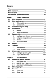
... AMD® CPU support list. AMD® 780G / SB700 Up to www.asus.com for AM2 CPU Dual-channel memory architecture - 2 x 240-pin DIMM slots support unbuffered ECC and non-ECC DDR2 1066*/800/667MHz memory modules - M4A78-VM IN/SI specifications summary CPU Chipset System bus Memory Graphics Expansion slots LAN Audio AMD...
... AMD® CPU support list. AMD® 780G / SB700 Up to www.asus.com for AM2 CPU Dual-channel memory architecture - 2 x 240-pin DIMM slots support unbuffered ECC and non-ECC DDR2 1066*/800/667MHz memory modules - M4A78-VM IN/SI specifications summary CPU Chipset System bus Memory Graphics Expansion slots LAN Audio AMD...
User Manual
Page 9
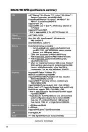
ix A RAID array over 2TB cannot be set as a data disk only. M4A78-VM IN/SI specifications summary Storage USB ASUS special features Back panel I/O ports Internal I /O shield User manual Drivers ASUS PC Probe II ASUS LiveUpdate Utility Anti-Virus software (OEM version) MicroATX form factor: 9.6 in x ... over 2TB can only be set as a boot disk. Supports up to 8 USB 2.0/1.1 ports (4 port at mid-board, 4 ports at back panel) ASUS Q-Fan ASUS CrashFree BIOS 3 ASUS EZ Flash 2 ASUS MyLogo 2 1 x PS/2 Keyboard port 1 x PS/2 Mouse port 1 x DVI port 1 x HDMI port 1 x VGA port 1 x LAN (...
ix A RAID array over 2TB cannot be set as a data disk only. M4A78-VM IN/SI specifications summary Storage USB ASUS special features Back panel I/O ports Internal I /O shield User manual Drivers ASUS PC Probe II ASUS LiveUpdate Utility Anti-Virus software (OEM version) MicroATX form factor: 9.6 in x ... over 2TB can only be set as a boot disk. Supports up to 8 USB 2.0/1.1 ports (4 port at mid-board, 4 ports at back panel) ASUS Q-Fan ASUS CrashFree BIOS 3 ASUS EZ Flash 2 ASUS MyLogo 2 1 x PS/2 Keyboard port 1 x PS/2 Mouse port 1 x DVI port 1 x HDMI port 1 x VGA port 1 x LAN (...
User Manual
Page 10
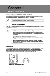
... mode. Chapter 1 Product introduction Thank you for the list of accessories. Failure to do so may cause severe damage to page ix for buying an ASUS® M4A78-VM IN/SI motherboard! Refer to the motherboard, peripherals, or components.
... mode. Chapter 1 Product introduction Thank you for the list of accessories. Failure to do so may cause severe damage to page ix for buying an ASUS® M4A78-VM IN/SI motherboard! Refer to the motherboard, peripherals, or components.

User Manual
Page 11
... intrusion connector (4-1 pin CHASSIS) 1-8 11. PCI / PCIe x16 slots 1-1 18. Serial port connector (10-1 pin COM1) Page 1-14 1-11 1-16 1-13 1-7 1-11 1-13 1-6 1-15 ASUS M4A78-VM IN/SI 1-2 DO NOT overtighten the screws! Doing so can damage the motherboard. 1.2.2 Layout contents Connectors/Jumpers/Slots/LED 1. USB device wake-up (3-pin USBPW1-4, 3-pin USBPW5...
... intrusion connector (4-1 pin CHASSIS) 1-8 11. PCI / PCIe x16 slots 1-1 18. Serial port connector (10-1 pin COM1) Page 1-14 1-11 1-16 1-13 1-7 1-11 1-13 1-6 1-15 ASUS M4A78-VM IN/SI 1-2 DO NOT overtighten the screws! Doing so can damage the motherboard. 1.2.2 Layout contents Connectors/Jumpers/Slots/LED 1. USB device wake-up (3-pin USBPW1-4, 3-pin USBPW5...
User Manual
Page 13
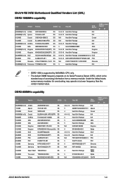
...; · · · · · · · · · · · · · · · · · · ASUS M4A78-VM IN/SI 1-4 DDR2-800MHz capability Size Vendor Part No. Chip Brand DIMM sockets support A* B* 4096MB(Kit of 2) A-Data AD21066E002GU DS 5-5-5-15 Heat-Sink Package N/A · 4096MB(kit...(Kit of 2) A-Data 512MB Apacer 1024MB Corsair 4096MB(kit of accessing information from a memory module. SS/DS CL Chip NO. M4A78-VM IN/SI Motherboard Qualified Vendors List (QVL) DDR2-1066MHz capability Size Vendor Part No.
...; · · · · · · · · · · · · · · · · · · ASUS M4A78-VM IN/SI 1-4 DDR2-800MHz capability Size Vendor Part No. Chip Brand DIMM sockets support A* B* 4096MB(Kit of 2) A-Data AD21066E002GU DS 5-5-5-15 Heat-Sink Package N/A · 4096MB(kit...(Kit of 2) A-Data 512MB Apacer 1024MB Corsair 4096MB(kit of accessing information from a memory module. SS/DS CL Chip NO. M4A78-VM IN/SI Motherboard Qualified Vendors List (QVL) DDR2-1066MHz capability Size Vendor Part No.

User Manual
Page 15
... settings, if any. Failure to the card. 3. Align the card connector with the screw. 6. Assign an IRQ to do not need to install expansion cards. ASUS M4A78-VM IN/SI 1-6 See Chapter 2 for information on the slot. 5. Secure the card to use. 4. otherwise, conflicts will arise between the two PCI groups, making the system...
... settings, if any. Failure to the card. 3. Align the card connector with the screw. 6. Assign an IRQ to do not need to install expansion cards. ASUS M4A78-VM IN/SI 1-6 See Chapter 2 for information on the slot. 5. Secure the card to use. 4. otherwise, conflicts will arise between the two PCI groups, making the system...

User Manual
Page 17
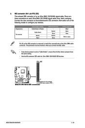
...-pin HDSW) This jumper allows you to pins 2-3. To enable the DVI feature, set this jumber to switch between the HDMI and the DVI features. ASUS M4A78-VM IN/SI 1-8 Set to +5VSB to wake up feature requires a power supply that can provide 500mA on the +5VSB lead for each USB port; To switch...
...-pin HDSW) This jumper allows you to pins 2-3. To enable the DVI feature, set this jumber to switch between the HDMI and the DVI features. ASUS M4A78-VM IN/SI 1-8 Set to +5VSB to wake up feature requires a power supply that can provide 500mA on the +5VSB lead for each USB port; To switch...
User Manual
Page 19
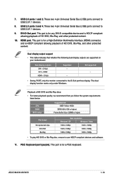
... has display. These two 4-pin Universal Serial Bus (USB) ports connect to USB 2.0/1.1 devices. 8. Playback of HD DVD, Blu-Ray, and other protected content. ASUS M4A78-VM IN/SI 1-10 This port is for a High-Definition Multimedia Interface (HDMI) connector, and is for any DVI-D compatible device and is HDCP compliant allowing playback of...
... has display. These two 4-pin Universal Serial Bus (USB) ports connect to USB 2.0/1.1 devices. 8. Playback of HD DVD, Blu-Ray, and other protected content. ASUS M4A78-VM IN/SI 1-10 This port is for a High-Definition Multimedia Interface (HDMI) connector, and is for any DVI-D compatible device and is HDCP compliant allowing playback of...
User Manual
Page 21
... Master Slave Mode of the following modes to match the covered hole on each Ultra DMA 133/100/66 signal cable: blue, black, and gray. ASUS M4A78-VM IN/SI 1-12
... Master Slave Mode of the following modes to match the covered hole on each Ultra DMA 133/100/66 signal cable: blue, black, and gray. ASUS M4A78-VM IN/SI 1-12

User Manual
Page 23
...a high-level signal to the fan connectors. Insufficient air flow inside the system may damage the motherboard components. Only the CPU fan supports the ASUS Q-Fan feature. 7. The signal is for a chassis-mounted intrusion detection sensor or switch. Remove the jumper caps only when you intend to this.... DO NOT place jumper caps on the motherboard, ensuring that the black wire of each cable matches the ground pin of the connector. ASUS M4A78-VM IN/SI 1-14 Connect the fan cables to the fan connectors on the fan connectors. Connect one end of 1A~2.22A (26.64W max.) at...
...a high-level signal to the fan connectors. Insufficient air flow inside the system may damage the motherboard components. Only the CPU fan supports the ASUS Q-Fan feature. 7. The signal is for a chassis-mounted intrusion detection sensor or switch. Remove the jumper caps only when you intend to this.... DO NOT place jumper caps on the motherboard, ensuring that the black wire of each cable matches the ground pin of the connector. ASUS M4A78-VM IN/SI 1-14 Connect the fan cables to the fan connectors on the fan connectors. Connect one end of 1A~2.22A (26.64W max.) at...
User Manual
Page 25
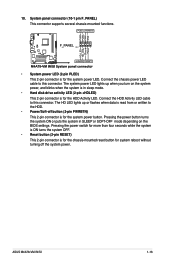
.... • Power/Soft-off the system power. Connect the HDD Activity LED cable to this connector. Connect the chassis power LED cable to this connector. ASUS M4A78-VM IN/SI 1-16 Pressing the power switch for more than four seconds while the system is ON turns the system OFF. • Reset button (2-pin RESET...
.... • Power/Soft-off the system power. Connect the HDD Activity LED cable to this connector. Connect the chassis power LED cable to this connector. ASUS M4A78-VM IN/SI 1-16 Pressing the power switch for more than four seconds while the system is ON turns the system OFF. • Reset button (2-pin RESET...
User Manual
Page 28
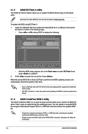
... port, then launch EZ Flash 2 in either of the following : ASUSTek EZ Flash 2 BIOS ROM Utility V3.36 FLASH TYPE: WOINBOND W25X80 Current ROM BOARD: M4A78-VM IN VER: 0308 (H:00 B:01) DATE: 04/29/2009 Update ROM BOARD: Unknown VER: Unknown DATE: Unknown PATH: A:\ A: Note [Enter] Select or Load [Tab] Switch...; Prepare the motherboard Support DVD or a USB flash disk containing the updated motherboard BIOS before using EZ Flash 2: 1. Download the latest BIOS file from the ASUS website at www.asus.com. otherwise, the utility will not function. 2-2 ASUS M4A78-VM IN/SI
... port, then launch EZ Flash 2 in either of the following : ASUSTek EZ Flash 2 BIOS ROM Utility V3.36 FLASH TYPE: WOINBOND W25X80 Current ROM BOARD: M4A78-VM IN VER: 0308 (H:00 B:01) DATE: 04/29/2009 Update ROM BOARD: Unknown VER: Unknown DATE: Unknown PATH: A:\ A: Note [Enter] Select or Load [Tab] Switch...; Prepare the motherboard Support DVD or a USB flash disk containing the updated motherboard BIOS before using EZ Flash 2: 1. Download the latest BIOS file from the ASUS website at www.asus.com. otherwise, the utility will not function. 2-2 ASUS M4A78-VM IN/SI
User Manual
Page 30
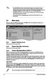
..., the Main menu screen appears, giving you are not user-configurable. Select [ARMD] (ATAPI Removable Media Device) if your screen. • Visit the ASUS website at www.asus.com to [Auto] allows automatic selection of IDE drive. Type [Auto] Selects the type of the appropriate IDE device type. Select [CDROM] if you... Setup Defaults item under the Exit menu. Configuration options: [Not Installed] [Auto] [CDROM] [ARMD] This item only appears in the Primary IDE Master/Slave menus. 2-4 ASUS M4A78-VM IN/SI These values are specifically configuring a CD-ROM drive.
..., the Main menu screen appears, giving you are not user-configurable. Select [ARMD] (ATAPI Removable Media Device) if your screen. • Visit the ASUS website at www.asus.com to [Auto] allows automatic selection of IDE drive. Type [Auto] Selects the type of the appropriate IDE device type. Select [CDROM] if you... Setup Defaults item under the Exit menu. Configuration options: [Not Installed] [Auto] [CDROM] [ARMD] This item only appears in the Primary IDE Master/Slave menus. 2-4 ASUS M4A78-VM IN/SI These values are specifically configuring a CD-ROM drive.
User Manual
Page 32
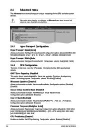
... for the normal operation. Configuration options: [Disabled] [Enabled] Cool 'n' Quiet [Enabled] Allows you to enable or disable the microcode updation. Configuration options: [Enabled] [Disabled] 2-6 ASUS M4A78-VM IN/SI Main Advanced Power BIOS SETUP UTILITY Boot Tools Exit Advanced Settings Hyper Transport Configuration CPU Configuration Chipset Onboard Devices Configuration PCIPnP USB Configuration Configure HT...
... for the normal operation. Configuration options: [Disabled] [Enabled] Cool 'n' Quiet [Enabled] Allows you to enable or disable the microcode updation. Configuration options: [Enabled] [Disabled] 2-6 ASUS M4A78-VM IN/SI Main Advanced Power BIOS SETUP UTILITY Boot Tools Exit Advanced Settings Hyper Transport Configuration CPU Configuration Chipset Onboard Devices Configuration PCIPnP USB Configuration Configure HT...
User Manual
Page 34
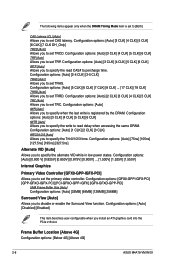
... [Auto] Allows you to specify when the last write is set to percharge time. Frame Buffer Location [Above 4G] Configuration options: [Below 4G] [Above 4G] 2-8 ASUS M4A78-VM IN/SI Configuration options: [Auto] [3 CLK] [4 CLK] [5 CLK] [6 CLK] TRP [Auto] Allows you to set TRP. Configuration options: [Auto] [75ns] [105ns] [127.5ns] [195ns] [327.5ns...
... [Auto] Allows you to specify when the last write is set to percharge time. Frame Buffer Location [Above 4G] Configuration options: [Below 4G] [Above 4G] 2-8 ASUS M4A78-VM IN/SI Configuration options: [Auto] [3 CLK] [4 CLK] [5 CLK] [6 CLK] TRP [Auto] Allows you to set TRP. Configuration options: [Auto] [75ns] [105ns] [127.5ns] [195ns] [327.5ns...
User Manual
Page 36
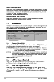
... drives. Legacy USB Support [Auto] Allows you to add additional tables as per Advanced Configuration and Power Interface (ACPI) 2.0 specifications. Configuration options: [Disabled] [Enabled] 2-10 ASUS M4A78-VM IN/SI
... drives. Legacy USB Support [Auto] Allows you to add additional tables as per Advanced Configuration and Power Interface (ACPI) 2.0 specifications. Configuration options: [Disabled] [Enabled] 2-10 ASUS M4A78-VM IN/SI
User Manual
Page 38
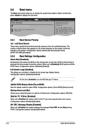
... options: [Force BIOS] [Keep Current] Bootup Num-Lock [On] Allows you to display the sub-menu. Configuration options: [Disabled] [Enabled] 2-12 ASUS M4A78-VM IN/SI Select an item then press to select the power-on state for the NumLock. Configuration options: [Removable Device] [Hard Drive] [ATAPI CD-ROM ] [...Setup during POST. The number of devices installed in the system. When set to Enabled, the system displays the message Press DEL to use the ASUS MyLogo 2™ feature. Configuration options: [Off] [On] Wait for 'F1' If Error [Enabled] When set the CD-ROM drive as ...
... options: [Force BIOS] [Keep Current] Bootup Num-Lock [On] Allows you to display the sub-menu. Configuration options: [Disabled] [Enabled] 2-12 ASUS M4A78-VM IN/SI Select an item then press to select the power-on state for the NumLock. Configuration options: [Removable Device] [Hard Drive] [ATAPI CD-ROM ] [...Setup during POST. The number of devices installed in the system. When set to Enabled, the system displays the message Press DEL to use the ASUS MyLogo 2™ feature. Configuration options: [Off] [On] Wait for 'F1' If Error [Enabled] When set the CD-ROM drive as ...
User Manual
Page 40
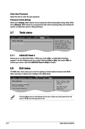
...the optimal or failsafe default values for user password when accessing the Setup utility. Clear User Password Select this item to exit. 2-14 ASUS M4A78-VM IN/SI Select one of the options from this menu or from the legend bar to clear the user password. Configuration options: [Setup] [Always...] 2.7 Tools menu Main Advanced Tools Settings ASUS EZ Flash 2 Power BIOS SETUP UTILITY Boot Tools Exit Press ENTER to [Always], BIOS checks for this...
...the optimal or failsafe default values for user password when accessing the Setup utility. Clear User Password Select this item to exit. 2-14 ASUS M4A78-VM IN/SI Select one of the options from this menu or from the legend bar to clear the user password. Configuration options: [Setup] [Always...] 2.7 Tools menu Main Advanced Tools Settings ASUS EZ Flash 2 Power BIOS SETUP UTILITY Boot Tools Exit Press ENTER to [Always], BIOS checks for this...