
User Manual
Page 1
Motherboard
Motherboard

User Manual
Page 1
M2N68 PLUS Motherboard
M2N68 PLUS Motherboard

User Manual
Page 3
Contents Notices...vi Safety information vii About this guide vii M2N68 PLUS specifications summary ix Chapter 1: Product introduction 1.1 Welcome 1-1 1.2 Package contents 1-1 1.3 Special features 1-1 1.3.1 Product highlights 1-1 1.3.2 Innovative ASUS features 1-3 1.4 Before you proceed 1-4 1.5 Motherboard overview 1-5 1.5.1 Placement direction 1-5 1.5.2 Screw holes 1-5 1.5.3 Motherboard layout 1-6 1.5.4 Layout contents 1-7 1.6 Central Processing Unit (CPU 1-7 1.6.1 Installing the CPU 1-7 1.6.2 Installing the heatsink and fan 1-9 1.7 System memory 1-10...
Contents Notices...vi Safety information vii About this guide vii M2N68 PLUS specifications summary ix Chapter 1: Product introduction 1.1 Welcome 1-1 1.2 Package contents 1-1 1.3 Special features 1-1 1.3.1 Product highlights 1-1 1.3.2 Innovative ASUS features 1-3 1.4 Before you proceed 1-4 1.5 Motherboard overview 1-5 1.5.1 Placement direction 1-5 1.5.2 Screw holes 1-5 1.5.3 Motherboard layout 1-6 1.5.4 Layout contents 1-7 1.6 Central Processing Unit (CPU 1-7 1.6.1 Installing the CPU 1-7 1.6.2 Installing the heatsink and fan 1-9 1.7 System memory 1-10...
User Manual
Page 6
... which can radiate radio frequency energy and, if not installed and used in accordance with manufacturer's instructions, may cause undesired operation. DO NOT throw the motherboard in municipal waste. Check local regulations for compliance could void the user's authority to operate this equipment does cause harmful interference to the following measures...
... which can radiate radio frequency energy and, if not installed and used in accordance with manufacturer's instructions, may cause undesired operation. DO NOT throw the motherboard in municipal waste. Check local regulations for compliance could void the user's authority to operate this equipment does cause harmful interference to the following measures...
User Manual
Page 7
...provided. If you are not sure about the voltage of the electrical outlet you are unplugged before you need when installing and configuring the motherboard. If you encounter technical problems with the package. • Before using the product, ensure that the power cables for the devices ..., keep paper clips, screws, and staples away from the system, ensure that all power cables are connected. Operation safety • Before installing the motherboard and adding devices on it may become wet. • Place the product on a stable surface. • If you detect any area where it...
...provided. If you are not sure about the voltage of the electrical outlet you are unplugged before you need when installing and configuring the motherboard. If you encounter technical problems with the package. • Before using the product, ensure that the power cables for the devices ..., keep paper clips, screws, and staples away from the system, ensure that all power cables are connected. Operation safety • Before installing the motherboard and adding devices on it may become wet. • Place the product on a stable surface. • If you detect any area where it...
User Manual
Page 11
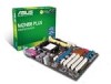
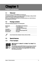
..., making it , check the items in your motherboard package for buying an ASUS® M2N68 PLUS motherboard! Chapter 1: Product introduction 1-1 Thank you start installing the motherboard, and hardware devices on it another standout in the new 45nm manufacturing process. Before you for the following items. Motherboard Cables Accessories Application DVD Documentation ASUS M2N68 PLUS motherboard 1 x Serial ATA cable 1 x Ultra DMA 133...
..., making it , check the items in your motherboard package for buying an ASUS® M2N68 PLUS motherboard! Chapter 1: Product introduction 1-1 Thank you start installing the motherboard, and hardware devices on it another standout in the new 45nm manufacturing process. Before you for the following items. Motherboard Cables Accessories Application DVD Documentation ASUS M2N68 PLUS motherboard 1 x Serial ATA cable 1 x Ultra DMA 133...
User Manual
Page 12
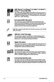
...JBOD configurations for a cool and quiet operating environment. ALC662 also supports the Windows® Vista Premium OS. 1-2 ASUS M2N68 PLUS AMD Cool 'n' Quiet Technology This motherboard supports the AMD Cool 'n' Quiet technology which provides faster data transfer rate and more bandwidth to provide efficient power ...jacks. It features dual-channel DDR2 1066 memory support, data transfer rate up to www.asus.com for advanced operating systems. Serial ATA 3Gb/s technology This motherboard supports hard drives based on the Serial ATA (SATA) 3Gb/s storage specifications. Gigabit ...
...JBOD configurations for a cool and quiet operating environment. ALC662 also supports the Windows® Vista Premium OS. 1-2 ASUS M2N68 PLUS AMD Cool 'n' Quiet Technology This motherboard supports the AMD Cool 'n' Quiet technology which provides faster data transfer rate and more bandwidth to provide efficient power ...jacks. It features dual-channel DDR2 1066 memory support, data transfer rate up to www.asus.com for advanced operating systems. Serial ATA 3Gb/s technology This motherboard supports hard drives based on the Serial ATA (SATA) 3Gb/s storage specifications. Gigabit ...
User Manual
Page 13
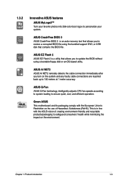
... immediately after you to update the BIOS without using a bootable floppy disk or an OS-based utility. 1.3.2 Innovative ASUS features ASUS MyLogo2™ Turn your system. ASUS Q-Fan ASUS Q-Fan technology intelligently adjusts CPU fan speeds according to system loading to personalize your favorite photos into 256-color boot... restore a corrupted BIOS file using the bundled support DVD, or USB disk that allows you turn on the environment. Green ASUS This motherboard and its packaging comply with the ASUS vision of Hazardous Substances (RoHS). Chapter 1: Product introduction 1-3
... immediately after you to update the BIOS without using a bootable floppy disk or an OS-based utility. 1.3.2 Innovative ASUS features ASUS MyLogo2™ Turn your system. ASUS Q-Fan ASUS Q-Fan technology intelligently adjusts CPU fan speeds according to system loading to personalize your favorite photos into 256-color boot... restore a corrupted BIOS file using the bundled support DVD, or USB disk that allows you turn on the environment. Green ASUS This motherboard and its packaging comply with the ASUS vision of Hazardous Substances (RoHS). Chapter 1: Product introduction 1-3
User Manual
Page 14
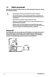
...power cord is switched off mode. The illustration below shows the location of the following precautions before you install motherboard components or change any motherboard settings. • Unplug the power cord from the wall socket before touching any component. • Use ... LED that lights up to the motherboard, peripherals, or components. M2N68 PLUS SB_PWR ON OFF Standby Power Powered Off M2N68 PLUS Onboard LED 1-4 ASUS M2N68 PLUS Onboard LED The motherboard comes with the component. • Before you install or remove any motherboard component. Failure to do so may...
...power cord is switched off mode. The illustration below shows the location of the following precautions before you install motherboard components or change any motherboard settings. • Unplug the power cord from the wall socket before touching any component. • Use ... LED that lights up to the motherboard, peripherals, or components. M2N68 PLUS SB_PWR ON OFF Standby Power Powered Off M2N68 PLUS Onboard LED 1-4 ASUS M2N68 PLUS Onboard LED The motherboard comes with the component. • Before you install or remove any motherboard component. Failure to do so may...
User Manual
Page 15
Place this side towards the rear of the chassis as indicated in the image below. 1.5.2 Screw holes Place six (6) screws into the chassis in the correct orientation. Chapter 1: Product introduction 1-5 Doing so can damage the motherboard. Do not overtighten the screws! 1.5 Motherboard overview 1.5.1 Placement direction When installing the motherboard, ensure that you place it into the holes indicated by circles to secure the motherboard to the chassis. The edge with external ports goes to the rear part of the chassis.
Place this side towards the rear of the chassis as indicated in the image below. 1.5.2 Screw holes Place six (6) screws into the chassis in the correct orientation. Chapter 1: Product introduction 1-5 Doing so can damage the motherboard. Do not overtighten the screws! 1.5 Motherboard overview 1.5.1 Placement direction When installing the motherboard, ensure that you place it into the holes indicated by circles to secure the motherboard to the chassis. The edge with external ports goes to the rear part of the chassis.
User Manual
Page 16
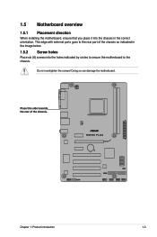
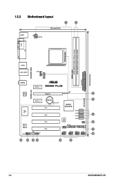
1.5.3 Motherboard layout 1 2 20.3cm(8.0in) KBMS ATX12V COM LPT CPU Socket DDR2-1066 DDR2 DIMM_A1 (64bit, 240-pin module) DDR2 DIMM_B1 (64bit, 240-pin module) EATXPWR 30.5cm(12.0in) 4PHASE POWER 5000HRS VRM USB34 LAN1_USB12 CPU_FAN AUDIO PCIEX1_1 M2N68 PLUS 1000M LAN Realtek PCIEX16 3 8211CL SATA RAID Lithium Cell 4 PCIEX1_2 CMOS Power PCI1 SB_PWR NVIDIA® MCP68 SE Super I/O SATA4 PCI2 SATA3 5 SATA2 ALC 662 AAFP PCI3 CD SPDIF_OUT PCI4 8Mb BIOS SATA1 6 CLRTC PRI_IDE SPEAKER 7 USB56 USB78 USB910 F_PANEL 8 14 13 12 11 10 9 1-6 ASUS M2N68 PLUS
1.5.3 Motherboard layout 1 2 20.3cm(8.0in) KBMS ATX12V COM LPT CPU Socket DDR2-1066 DDR2 DIMM_A1 (64bit, 240-pin module) DDR2 DIMM_B1 (64bit, 240-pin module) EATXPWR 30.5cm(12.0in) 4PHASE POWER 5000HRS VRM USB34 LAN1_USB12 CPU_FAN AUDIO PCIEX1_1 M2N68 PLUS 1000M LAN Realtek PCIEX16 3 8211CL SATA RAID Lithium Cell 4 PCIEX1_2 CMOS Power PCI1 SB_PWR NVIDIA® MCP68 SE Super I/O SATA4 PCI2 SATA3 5 SATA2 ALC 662 AAFP PCI3 CD SPDIF_OUT PCI4 8Mb BIOS SATA1 6 CLRTC PRI_IDE SPEAKER 7 USB56 USB78 USB910 F_PANEL 8 14 13 12 11 10 9 1-6 ASUS M2N68 PLUS

User Manual
Page 17
.../Slots 1. CPU fan connector (4-pin CPU_FAN) 5. USB connectors (10-1 pin USB56, USB78, USB910) 1-7 10. Locate the CPU socket on this motherboard. 1.6.1 Installing the CPU To install a CPU: 1. System panel connector (10-1 pin F_PANEL) 1-10 9. Onboard LED (SB_PWR) Page 1-23 1-...20 1-17 1-22 1-17 1-20 1-4 1.6 Central Processing Unit (CPU) The motherboard comes with AMD® Opteron™ processors. Chapter 1: Product introduction 1-7 Digital audio connector (4-1 pin SPDIF_OUT) 1-19 12. Clear RTC RAM (3-pin ...
.../Slots 1. CPU fan connector (4-pin CPU_FAN) 5. USB connectors (10-1 pin USB56, USB78, USB910) 1-7 10. Locate the CPU socket on this motherboard. 1.6.1 Installing the CPU To install a CPU: 1. System panel connector (10-1 pin F_PANEL) 1-10 9. Onboard LED (SB_PWR) Page 1-23 1-...20 1-17 1-22 1-17 1-20 1-4 1.6 Central Processing Unit (CPU) The motherboard comes with AMD® Opteron™ processors. Chapter 1: Product introduction 1-7 Digital audio connector (4-1 pin SPDIF_OUT) 1-19 12. Clear RTC RAM (3-pin ...
User Manual
Page 18
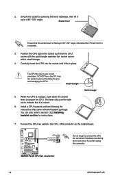
...; angle, otherwise the CPU will not fit in place, push down the socket lever to plug this connector. 1-8 ASUS M2N68 PLUS You can occur if you fail to secure the CPU. DO NOT force the CPU into the socket until it fits in one correct orientation. The lever clicks on the motherboard. Gold triangle 7.
...; angle, otherwise the CPU will not fit in place, push down the socket lever to plug this connector. 1-8 ASUS M2N68 PLUS You can occur if you fail to secure the CPU. DO NOT force the CPU into the socket until it fits in one correct orientation. The lever clicks on the motherboard. Gold triangle 7.
User Manual
Page 19
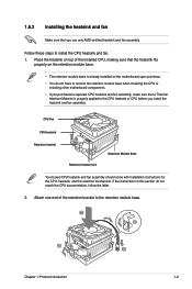
If the instructions in this section do not have to remove the retention module base when installing the CPU or installing other motherboard components. • If you purchased a separate CPU heatsink and fan assembly, make sure that a Thermal Interface Material is already installed on ... boxed CPU heatsink and fan assembly should come with installation instructions for the CPU, heatsink, and the retention mechanism. Place the heatsink on the motherboard upon purchase. • You do not match the CPU documentation, follow the latter. 2. Attach one end of the installed CPU, making sure...
If the instructions in this section do not have to remove the retention module base when installing the CPU or installing other motherboard components. • If you purchased a separate CPU heatsink and fan assembly, make sure that a Thermal Interface Material is already installed on ... boxed CPU heatsink and fan assembly should come with installation instructions for the CPU, heatsink, and the retention mechanism. Place the heatsink on the motherboard upon purchase. • You do not match the CPU documentation, follow the latter. 2. Attach one end of the installed CPU, making sure...
User Manual
Page 20
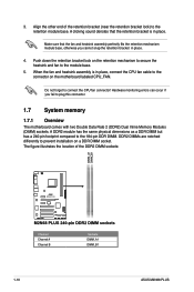
...on a DDR DIMM socket. DDR2 DIMMs are notched differently to plug this connector. 1.7 System memory 1.7.1 Overview The motherboard comes with two Double Data Rate 2 (DDR2) Dual Inline Memory Modules (DIMM) sockets. The figure illustrates the ...fan and heatsink assembly perfectly fits the retention mechanism module base, otherwise you fail to prevent installation on the motherboard labeled CPU_FAN. Make sure that the retention bracket is in place, connect the CPU fan cable to the... the DDR2 DIMM sockets: Channel Channel A Channel B 1-10 Sockets DIMM_A1 DIMM_B1 ASUS M2N68 PLUS
...on a DDR DIMM socket. DDR2 DIMMs are notched differently to plug this connector. 1.7 System memory 1.7.1 Overview The motherboard comes with two Double Data Rate 2 (DDR2) Dual Inline Memory Modules (DIMM) sockets. The figure illustrates the ...fan and heatsink assembly perfectly fits the retention mechanism module base, otherwise you fail to prevent installation on the motherboard labeled CPU_FAN. Make sure that the retention bracket is in place, connect the CPU fan cable to the... the DDR2 DIMM sockets: Channel Channel A Channel B 1-10 Sockets DIMM_A1 DIMM_B1 ASUS M2N68 PLUS
User Manual
Page 21
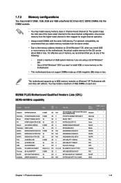
M2N68 PLUS Motherboard Qualified Vendors Lists (QVL) DDR2-667MHz capability Vendor Part No. Size ...Product introduction 1-11 Install a maximum of 3GB system memory if you install 4GB or more memory on the motherboard. • This motherboard does not support DIMMs made up to 8GB memory modules on Windows® XP Professional x64 and Vista x64 ... address limitation on 32-bit Windows® OS, when you are using a 32-bit Windows® OS. - The motherboard supports up of 256 megabits (Mb) chips or less. Chip Brand DIMM support A* B* Kingston KVR667D2N5/512 512MB SS N/A...
M2N68 PLUS Motherboard Qualified Vendors Lists (QVL) DDR2-667MHz capability Vendor Part No. Size ...Product introduction 1-11 Install a maximum of 3GB system memory if you install 4GB or more memory on the motherboard. • This motherboard does not support DIMMs made up to 8GB memory modules on Windows® XP Professional x64 and Vista x64 ... address limitation on 32-bit Windows® OS, when you are using a 32-bit Windows® OS. - The motherboard supports up of 256 megabits (Mb) chips or less. Chip Brand DIMM support A* B* Kingston KVR667D2N5/512 512MB SS N/A...

User Manual
Page 23
... DIMM from the socket. Unlock a DDR2 DIMM socket by pressing the retaining clips outward. 2. Failure to do so can cause severe damage to both the motherboard and the components. 1. Firmly insert the DIMM into a socket to unlock the DIMM. Locked Retaining Clip 1.7.4 Removing a DIMM To remove a DIMM: 1. Support the DIMM lightly...
... DIMM from the socket. Unlock a DDR2 DIMM socket by pressing the retaining clips outward. 2. Failure to do so can cause severe damage to both the motherboard and the components. 1. Firmly insert the DIMM into a socket to unlock the DIMM. Locked Retaining Clip 1.7.4 Removing a DIMM To remove a DIMM: 1. Support the DIMM lightly...
User Manual
Page 24
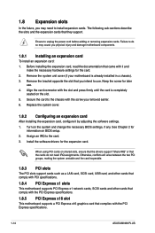
... physical injury and damage motherboard components. 1.8.1 Installing an expansion card To install an expansion card: 1. Remove the bracket opposite the slot that you may cause you removed earlier. 6. Secure the card to the chassis with the PCI Express specifications. 1-14 ASUS M2N68 PLUS Remove the system unit cover... (if your motherboard is completely seated on BIOS setup. 2. Ensure to the card. 3.
... physical injury and damage motherboard components. 1.8.1 Installing an expansion card To install an expansion card: 1. Remove the bracket opposite the slot that you may cause you removed earlier. 6. Secure the card to the chassis with the PCI Express specifications. 1-14 ASUS M2N68 PLUS Remove the system unit cover... (if your motherboard is completely seated on BIOS setup. 2. Ensure to the card. 3.
User Manual
Page 28
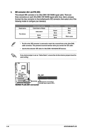
.... IDE connector (40-1 pin PRI_IDE) The onboard IDE connector is set as "Cable-Select", ensure that all other device jumpers have the same setting. 1-18 ASUS M2N68 PLUS Connect the blue connector to the motherboard's IDE connector, then select one of device(s) -
.... IDE connector (40-1 pin PRI_IDE) The onboard IDE connector is set as "Cable-Select", ensure that all other device jumpers have the same setting. 1-18 ASUS M2N68 PLUS Connect the blue connector to the motherboard's IDE connector, then select one of device(s) -
User Manual
Page 30
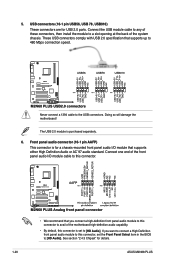
... these connectors, then install the module to a slot opening at the back of the motherboard high-definition audio capability. • By default, this connector, set to [HD Audio]. Doing so will damage the motherboard! If you connect a high-definition front panel audio module to this connector. •... pin AAFP) This connector is purchased separately. 6. USB connectors (10-1 pin USB56, USB 78, USB910) These connectors are for details. 1-20 ASUS M2N68 PLUS Connect one end of the front panel audio I /O module that supports either High Definition Audio or AC`97 audio standard.
... these connectors, then install the module to a slot opening at the back of the motherboard high-definition audio capability. • By default, this connector, set to [HD Audio]. Doing so will damage the motherboard! If you connect a high-definition front panel audio module to this connector. •... pin AAFP) This connector is purchased separately. 6. USB connectors (10-1 pin USB56, USB 78, USB910) These connectors are for details. 1-20 ASUS M2N68 PLUS Connect one end of the front panel audio I /O module that supports either High Definition Audio or AC`97 audio standard.


