
User Manual
Page 31
Version 1.19(ASUS V2.07(03.11.24BB)) Copyright (C) 2002 American Megatrends, Inc. All rights reserved. exe 2 DOS afudos /o[filename filename A:\>afudos /oOLDBIOS1.rom 3. 按下 afudos /oOLDBIOS1.rom AMI Firmware Update Utility - Reading flash ..... BIOS 2.1 使用 AFUDOS BIOS AFUDOS DOS BIOS BIOS 程式。AFUDOS BIOS BIOS BIOS 程式 BIOS 程式。 1.2MB BIOS 1 AFUDOS 程式(afudos. ok A:\> 當 BIOS DOS 31 done Write to file......
Version 1.19(ASUS V2.07(03.11.24BB)) Copyright (C) 2002 American Megatrends, Inc. All rights reserved. exe 2 DOS afudos /o[filename filename A:\>afudos /oOLDBIOS1.rom 3. 按下 afudos /oOLDBIOS1.rom AMI Firmware Update Utility - Reading flash ..... BIOS 2.1 使用 AFUDOS BIOS AFUDOS DOS BIOS BIOS 程式。AFUDOS BIOS BIOS BIOS 程式 BIOS 程式。 1.2MB BIOS 1 AFUDOS 程式(afudos. ok A:\> 當 BIOS DOS 31 done Write to file......

User Manual
Page 32
... Check ...... Do not turn off power during flash BIOS Reading file ....... Version 1.19(ASUS V2.07(03.11.24BB)) Copyright (C) 2002 American Megatrends, Inc. 更新 BIOS 程式 AFUDOS BIOS 程式。 1 tw.asus.com BIOS 片中。 BIOS BIOS 2. 將 AFUDOS.EXE BIOS 3 DOS afudos /i[filename filename BIOS 程式。 A:\>afudos /iP5B-VM DO.ROM...
... Check ...... Do not turn off power during flash BIOS Reading file ....... Version 1.19(ASUS V2.07(03.11.24BB)) Copyright (C) 2002 American Megatrends, Inc. 更新 BIOS 程式 AFUDOS BIOS 程式。 1 tw.asus.com BIOS 片中。 BIOS BIOS 2. 將 AFUDOS.EXE BIOS 3 DOS afudos /i[filename filename BIOS 程式。 A:\>afudos /iP5B-VM DO.ROM...

User Manual
Page 33
... Message: Do You Want To Save Bios (Y/N) 33 2.2 使用 AwardBIOS Flash BIOS AwardBIOS Flash AwardBIOS Flash 程式(AWDFLASH.EXE BIOS AwardBIOS Flash BIOS 程式。 1 http://tw.asus.com BIOS M2N-VM HDMI.bin FAT 32/16 格式的 USB BIOS 2 CD/DVD AwardBIOS Flash BIOS 3 DOS 4. 當 A BIOS 檔案與 AwardBIOS Flash...
... Message: Do You Want To Save Bios (Y/N) 33 2.2 使用 AwardBIOS Flash BIOS AwardBIOS Flash AwardBIOS Flash 程式(AWDFLASH.EXE BIOS AwardBIOS Flash BIOS 程式。 1 http://tw.asus.com BIOS M2N-VM HDMI.bin FAT 32/16 格式的 USB BIOS 2 CD/DVD AwardBIOS Flash BIOS 3 DOS 4. 當 A BIOS 檔案與 AwardBIOS Flash...

User Manual
Page 34
... Flash Type - OFE00 OK Write OK No Update Write Fail Warning: Don't Turn Off Power Or Reset System! 在更新 BIOS 9 Flash Complete BIOS F1 AwardBIOS Flash Utility for ASUS V1.14 (C) Phoenix Technologies Ltd. PMC Pm49FL004T LPC/FWH File Name to Continue Write OK F1 Reset No Update Write Fail 34...
... Flash Type - OFE00 OK Write OK No Update Write Fail Warning: Don't Turn Off Power Or Reset System! 在更新 BIOS 9 Flash Complete BIOS F1 AwardBIOS Flash Utility for ASUS V1.14 (C) Phoenix Technologies Ltd. PMC Pm49FL004T LPC/FWH File Name to Continue Write OK F1 Reset No Update Write Fail 34...

User Manual
Page 4
Contents 1.11 Software support 1-24 1.11.1 Installing an operating system 1-24 1.11.2 Support DVD information 1-24 Chapter 2 BIOS information 2.1 Managing and updating your BIOS 2-1 2.1.1 ASUS Update utility 2-1 2.1.2 ASUS EZ Flash 2 utility 2-2 2.1.3 ASUS CrashFree BIOS 3 utility 2-3 2.2 BIOS setup program 2-4 2.2.1 BIOS menu screen 2-5 2.2.2 Menu bar 2-5 2.2.3 Navigation keys 2-6 2.2.4 Menu items 2-6 2.2.5 Submenu items 2-6 2.2.6 Configuration fields 2-6 2.2.7 General help 2-6 2.2.8 Pop-up window 2-6 2.2.9 Scroll bar 2-6 2.3 Main...
Contents 1.11 Software support 1-24 1.11.1 Installing an operating system 1-24 1.11.2 Support DVD information 1-24 Chapter 2 BIOS information 2.1 Managing and updating your BIOS 2-1 2.1.1 ASUS Update utility 2-1 2.1.2 ASUS EZ Flash 2 utility 2-2 2.1.3 ASUS CrashFree BIOS 3 utility 2-3 2.2 BIOS setup program 2-4 2.2.1 BIOS menu screen 2-5 2.2.2 Menu bar 2-5 2.2.3 Navigation keys 2-6 2.2.4 Menu items 2-6 2.2.5 Submenu items 2-6 2.2.6 Configuration fields 2-6 2.2.7 General help 2-6 2.2.8 Pop-up window 2-6 2.2.9 Scroll bar 2-6 2.3 Main...
User Manual
Page 7
... Place the product on it by yourself. Detailed descriptions of the motherboard and the new technology it supports. • Chapter 2: BIOS information This chapter tells how to fix it , carefully read all power cables from the existing system before you need when installing ...power supply is organized This guide contains the following parts: • Chapter 1: Product introduction This chapter describes the features of the BIOS parameters are using an adapter or extension cord. Safety information Electrical safety • To prevent electrical shock hazard, disconnect the power cable...
... Place the product on it by yourself. Detailed descriptions of the motherboard and the new technology it supports. • Chapter 2: BIOS information This chapter tells how to fix it , carefully read all power cables from the existing system before you need when installing ...power supply is organized This guide contains the following parts: • Chapter 1: Product introduction This chapter describes the features of the BIOS parameters are using an adapter or extension cord. Safety information Electrical safety • To prevent electrical shock hazard, disconnect the power cable...
User Manual
Page 10
M2N68 PLUS specifications summary Back panel I/O ports Internal I/O connectors BIOS Accessories Form Factor Support DVD 1 x PS/2 Keyboard port 1 x PS/2 Mouse port 1 x LAN (RJ45) port 4 x USB 2.0/1.1 ports 6-channel Audio ports 1 x LPT port 1 x COM port 3 x USB...Speaker connector 1 x S/PDIF Out connector 1 x CPU Fan connector 1 x 24-pin EATX power connector 1 x 4-pin ATX 12V power connector 1 x system panel connector 8Mb Flash ROM, AMI BIOS, PnP, DMI2.0, WfM2.0, ACPI2.0a, SM BIOS2.5 1 x Serial ATA cable 1 x UltraDMA 133/100/66 cable 1x I/O Shield User manual ATX form factor: 12'' x 8'' (30....
M2N68 PLUS specifications summary Back panel I/O ports Internal I/O connectors BIOS Accessories Form Factor Support DVD 1 x PS/2 Keyboard port 1 x PS/2 Mouse port 1 x LAN (RJ45) port 4 x USB 2.0/1.1 ports 6-channel Audio ports 1 x LPT port 1 x COM port 3 x USB...Speaker connector 1 x S/PDIF Out connector 1 x CPU Fan connector 1 x 24-pin EATX power connector 1 x 4-pin ATX 12V power connector 1 x system panel connector 8Mb Flash ROM, AMI BIOS, PnP, DMI2.0, WfM2.0, ACPI2.0a, SM BIOS2.5 1 x Serial ATA cable 1 x UltraDMA 133/100/66 cable 1x I/O Shield User manual ATX form factor: 12'' x 8'' (30....
User Manual
Page 13
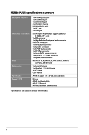
... NET2 remotely detects the cable connection immediately after you to ensure quiet, cool, and efficient operation. 1.3.2 Innovative ASUS features ASUS MyLogo2™ Turn your system. ASUS CrashFree BIOS 3 ASUS CrashFree BIOS 3 is in line with the European Union's Restriction on the system and any faulty cable connections are reported back up to personalize your favorite photos...
... NET2 remotely detects the cable connection immediately after you to ensure quiet, cool, and efficient operation. 1.3.2 Innovative ASUS features ASUS MyLogo2™ Turn your system. ASUS CrashFree BIOS 3 ASUS CrashFree BIOS 3 is in line with the European Union's Restriction on the system and any faulty cable connections are reported back up to personalize your favorite photos...
User Manual
Page 16
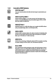
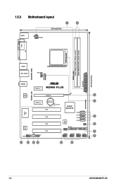
1.5.3 Motherboard layout 1 2 20.3cm(8.0in) KBMS ATX12V COM LPT CPU Socket DDR2-1066 DDR2 DIMM_A1 (64bit, 240-pin module) DDR2 DIMM_B1 (64bit, 240-pin module) EATXPWR 30.5cm(12.0in) 4PHASE POWER 5000HRS VRM USB34 LAN1_USB12 CPU_FAN AUDIO PCIEX1_1 M2N68 PLUS 1000M LAN Realtek PCIEX16 3 8211CL SATA RAID Lithium Cell 4 PCIEX1_2 CMOS Power PCI1 SB_PWR NVIDIA® MCP68 SE Super I/O SATA4 PCI2 SATA3 5 SATA2 ALC 662 AAFP PCI3 CD SPDIF_OUT PCI4 8Mb BIOS SATA1 6 CLRTC PRI_IDE SPEAKER 7 USB56 USB78 USB910 F_PANEL 8 14 13 12 11 10 9 1-6 ASUS M2N68 PLUS
1.5.3 Motherboard layout 1 2 20.3cm(8.0in) KBMS ATX12V COM LPT CPU Socket DDR2-1066 DDR2 DIMM_A1 (64bit, 240-pin module) DDR2 DIMM_B1 (64bit, 240-pin module) EATXPWR 30.5cm(12.0in) 4PHASE POWER 5000HRS VRM USB34 LAN1_USB12 CPU_FAN AUDIO PCIEX1_1 M2N68 PLUS 1000M LAN Realtek PCIEX16 3 8211CL SATA RAID Lithium Cell 4 PCIEX1_2 CMOS Power PCI1 SB_PWR NVIDIA® MCP68 SE Super I/O SATA4 PCI2 SATA3 5 SATA2 ALC 662 AAFP PCI3 CD SPDIF_OUT PCI4 8Mb BIOS SATA1 6 CLRTC PRI_IDE SPEAKER 7 USB56 USB78 USB910 F_PANEL 8 14 13 12 11 10 9 1-6 ASUS M2N68 PLUS
User Manual
Page 24
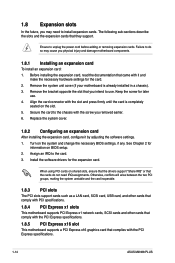
...2 for the card. 2. Secure the card to do not need to the card. 3. When using PCI cards on BIOS setup. 2. Failure to the chassis with the PCI Express specifications. 1-14 ASUS M2N68 PLUS Replace the system cover. 1.8.2 Configuring an expansion card After installing the expansion card, configure it and make the necessary hardware... adding or removing expansion cards. Remove the system unit cover (if your motherboard is completely seated on the system and change the necessary BIOS settings, if any. Align the card connector with it by adjusting the software settings. 1.
...2 for the card. 2. Secure the card to do not need to the card. 3. When using PCI cards on BIOS setup. 2. Failure to the chassis with the PCI Express specifications. 1-14 ASUS M2N68 PLUS Replace the system cover. 1.8.2 Configuring an expansion card After installing the expansion card, configure it and make the necessary hardware... adding or removing expansion cards. Remove the system unit cover (if your motherboard is completely seated on the system and change the necessary BIOS settings, if any. Align the card connector with it by adjusting the software settings. 1.
User Manual
Page 25
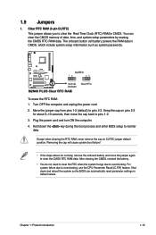
.... Move the jumper cap from pins 1-2 (default) to overclocking, use the CPU Parameter Recall (C.P.R) feature. Hold down and reboot the system so the BIOS can clear the CMOS memory of date, time, and system setup parameters by erasing the CMOS RTC RAM data. For system failure due to pins... due to default values. The onboard button cell battery powers the RAM data in CMOS. Shut down the key during the boot process and enter BIOS setup to pins 1-2. 3. After clearing the CMOS, reinstall the battery. • You do not help, remove the onboard battery and move the cap...
.... Move the jumper cap from pins 1-2 (default) to overclocking, use the CPU Parameter Recall (C.P.R) feature. Hold down and reboot the system so the BIOS can clear the CMOS memory of date, time, and system setup parameters by erasing the CMOS RTC RAM data. For system failure due to pins... due to default values. The onboard button cell battery powers the RAM data in CMOS. Shut down the key during the boot process and enter BIOS setup to pins 1-2. 3. After clearing the CMOS, reinstall the battery. • You do not help, remove the onboard battery and move the cap...
User Manual
Page 29
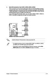
... Serial ATA signal cables for details. Install the Windows® XP Service Pack 1 before using these connectors, set the nVidia RAID Function item in the BIOS to the RAID manual in the support DVD. • If you can create a RAID 0, RAID 1, RAID 0+1, RAID 5, and JBOD configurations through the onboard controller. The...
... Serial ATA signal cables for details. Install the Windows® XP Service Pack 1 before using these connectors, set the nVidia RAID Function item in the BIOS to the RAID manual in the support DVD. • If you can create a RAID 0, RAID 1, RAID 0+1, RAID 5, and JBOD configurations through the onboard controller. The...
User Manual
Page 30
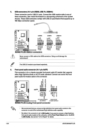
... comply with USB 2.0 specification that supports up to the USB connectors. The USB 2.0 module is set the Front Panel Select item in the BIOS to [HD Audio]. Front panel audio connector (10-1 pin AAFP) This connector is for a chassis-mounted front panel audio I /O module cable to.... See section "2.4.3 Chipset" for USB 2.0 ports. USB connectors (10-1 pin USB56, USB 78, USB910) These connectors are for details. 1-20 ASUS M2N68 PLUS Connect the USB module cable to any of these connectors, then install the module to a slot opening at the back of the motherboard high-definition...
... comply with USB 2.0 specification that supports up to the USB connectors. The USB 2.0 module is set the Front Panel Select item in the BIOS to [HD Audio]. Front panel audio connector (10-1 pin AAFP) This connector is for a chassis-mounted front panel audio I /O module cable to.... See section "2.4.3 Chipset" for USB 2.0 ports. USB connectors (10-1 pin USB56, USB 78, USB910) These connectors are for details. 1-20 ASUS M2N68 PLUS Connect the USB module cable to any of these connectors, then install the module to a slot opening at the back of the motherboard high-definition...

User Manual
Page 33
Ground Reset +HD_LED RESET M2N68 PLUS System panel connector • System power LED (2-pin PWRLED) This 2-pin connector is for the system power LED. Connect the chassis power LED cable to ... drive activity LED (2-pin HDLED) This 2-pin connector is for the HDD Activity LED. Chapter 1: Product introduction 1-23 PWR LED PWR BTN PLED+ PLEDPWR GND M2N68 PLUS F_PANEL PIN 1 IDE_LED+ IDE_LED- Connect the HDD Activity LED cable to this connector. The IDE LED lights up when you turn on the system power...
Ground Reset +HD_LED RESET M2N68 PLUS System panel connector • System power LED (2-pin PWRLED) This 2-pin connector is for the system power LED. Connect the chassis power LED cable to ... drive activity LED (2-pin HDLED) This 2-pin connector is for the HDD Activity LED. Chapter 1: Product introduction 1-23 PWR LED PWR BTN PLED+ PLEDPWR GND M2N68 PLUS F_PANEL PIN 1 IDE_LED+ IDE_LED- Connect the HDD Activity LED cable to this connector. The IDE LED lights up when you turn on the system power...
User Manual
Page 35
... a copy of the updating process: Updating from the Internet, then click Next. Select the ASUS FTP site nearest you update the BIOS using the ASUS Update or AFUDOS utilities. 2.1.1 ASUS Update utility The ASUS Update is available in the future. Select Update BIOS from the Internet a. Quit all Windows® applications before you to restore the...
... a copy of the updating process: Updating from the Internet, then click Next. Select the ASUS FTP site nearest you update the BIOS using the ASUS Update or AFUDOS utilities. 2.1.1 ASUS Update utility The ASUS Update is available in the future. Select Update BIOS from the Internet a. Quit all Windows® applications before you to restore the...
User Manual
Page 36
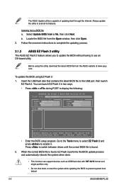
...32/16 format and single partition only. • Do not shut down or reset the system while updating the BIOS to prevent system boot failure! 2-2 ASUS M2N68 PLUS Select Update BIOS from a BIOS file a. Go to the Tools menu to select EZ Flash 2 and press to use an OS‑based ...utility. Updating from a file, then click Next. Locate the BIOS file from the ASUS website at www.asus. When the correct BIOS file is found . 2....
...32/16 format and single partition only. • Do not shut down or reset the system while updating the BIOS to prevent system boot failure! 2-2 ASUS M2N68 PLUS Select Update BIOS from a BIOS file a. Go to the Tools menu to select EZ Flash 2 and press to use an OS‑based ...utility. Updating from a file, then click Next. Locate the BIOS file from the ASUS website at www.asus. When the correct BIOS file is found . 2....
User Manual
Page 37
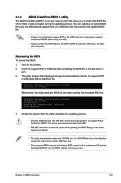
... • The utility automatically checks the CD-ROM first. Bad BIOS checksum. CD-ROM found , the utility reads the BIOS file and starts erasing the corrupted BIOS file. Doing so can support ASUS CrashFree BIOS 3. Turn on the system. 2. Insert the support DVD or ...USB flash disk containing the BIOS file to the SATA1/ SATA 2 connector. Starting BIOS recovery... Checking for CD-ROM... You can update a corrupted BIOS file using this motherboard. Start erasing... 4. 2.1.3 ASUS CrashFree BIOS 3 utility The ASUS CrashFree BIOS 3 is found, the utility then checks the...
... • The utility automatically checks the CD-ROM first. Bad BIOS checksum. CD-ROM found , the utility reads the BIOS file and starts erasing the corrupted BIOS file. Doing so can support ASUS CrashFree BIOS 3. Turn on the system. 2. Insert the support DVD or ...USB flash disk containing the BIOS file to the SATA1/ SATA 2 connector. Starting BIOS recovery... Checking for CD-ROM... You can update a corrupted BIOS file using this motherboard. Start erasing... 4. 2.1.3 ASUS CrashFree BIOS 3 utility The ASUS CrashFree BIOS 3 is found, the utility then checks the...
User Manual
Page 38
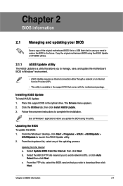
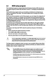
Use the BIOS Setup program when you are installing a motherboard, reconfiguring your system using the provided utility described in this motherboard. 2-4 ASUS M2N68 PLUS This section explains how to configure your system, or prompted to use as possible. Even if you are for ...this program. This requires you to reconfigure your system using the navigation keys. • The default BIOS settings for reference purposes only,...
Use the BIOS Setup program when you are installing a motherboard, reconfiguring your system using the provided utility described in this motherboard. 2-4 ASUS M2N68 PLUS This section explains how to configure your system, or prompted to use as possible. Even if you are for ...this program. This requires you to reconfigure your system using the navigation keys. • The default BIOS settings for reference purposes only,...

User Manual
Page 39
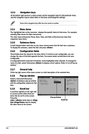
...item on the menu bar, press the right or left arrow key on the keyboard until the desired item is highlighted. • The BIOS setup screens shown in this chapter are for reference purposes only, and may not exactly match what you see on top of the screen ...bar The menu bar on your screen. • Visit the ASUS website at www.asus.com to configure system Time. Use [+] or [-] to download the latest BIOS information. 2.2.1 BIOS menu screen Menu items Menu bar Configuration fields General help Main Advanced Power BIOS SETUP UTILITY Boot Tools Exit System Time 19:34:30] ...
...item on the menu bar, press the right or left arrow key on the keyboard until the desired item is highlighted. • The BIOS setup screens shown in this chapter are for reference purposes only, and may not exactly match what you see on top of the screen ...bar The menu bar on your screen. • Visit the ASUS website at www.asus.com to configure system Time. Use [+] or [-] to download the latest BIOS information. 2.2.1 BIOS menu screen Menu items Menu bar Configuration fields General help Main Advanced Power BIOS SETUP UTILITY Boot Tools Exit System Time 19:34:30] ...
User Manual
Page 40
... enclosed in the menu and change the value of a field, select it then press to display a pop-up window Scroll bar 2-6 ASUS M2N68 PLUS Press the / arrow keys or / keys to another. 2.2.4 Menu items The highlighted item on the menu bar displays the specific items for... submenu. 2.2.3 Navigation keys At the bottom right corner of a menu screen are items that do not fit on the screen. Main Advanced BIOS SETUP UTILITY Power Boot Tools Exit Suspend Mode ACPI 2.0 Support ACPI APIC support APM Configuration Hardware Monitor [Auto] [Disabled] [EDniOsapabtbilloendesd] Enabled...
... enclosed in the menu and change the value of a field, select it then press to display a pop-up window Scroll bar 2-6 ASUS M2N68 PLUS Press the / arrow keys or / keys to another. 2.2.4 Menu items The highlighted item on the menu bar displays the specific items for... submenu. 2.2.3 Navigation keys At the bottom right corner of a menu screen are items that do not fit on the screen. Main Advanced BIOS SETUP UTILITY Power Boot Tools Exit Suspend Mode ACPI 2.0 Support ACPI APIC support APM Configuration Hardware Monitor [Auto] [Disabled] [EDniOsapabtbilloendesd] Enabled...


