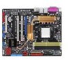
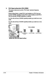
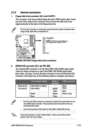
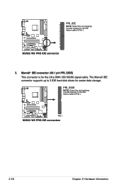
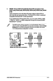
M2N32 WS Professional English Edition User's Manual
Page 27
SB_PWR M2N32 WS PRO ® ON Standby Power M2N32 WS PRO Onboard LED OFF Powered Off ASUS M2N32 WS Professional 2- The illustration below shows the location of the following precautions before removing or plugging in any motherboard settings. • Unplug the power cord from the ...
M2N32 WS Professional English Edition User's Manual
Page 28
... physical injury and damage motherboard components. 2.2.1 Placement direction When installing the motherboard, make sure that you install the motherboard, study the configuration of the chassis M2N32 WS PRO ® 2- Chapter 2: Hardware information 2.2 Motherboard overview Before you place it . Failure to the rear part of the chassis as indicated in the image below. 2.2.2 Screw...
M2N32 WS Professional English Edition User's Manual
Page 33
... designed for the AMD Athlon™ 64 X2/Athlon™ 64 FX/Athlon™ 64/Sempron™ processor. M2N32 WS PRO ® M2N32 WS PRO CPU Socket AM2 2. otherwise, the CPU will not fit in only one correct orientation. ASUS M2N32 WS Professional 2- Locate the CPU socket on the socket and damaging the CPU! 2.3.1 Installing the CPU To install a CPU...
M2N32 WS Professional English Edition User's Manual
Page 37
CPU_FAN GND CPU FAN PWR CPU FAN IN CPU FAN PWM M2N32 WS PRO ® M2N32 WS PRO CPU fan connector Do not forget to plug this connector. Hardware monitoring errors can occur if you fail to connect the CPU fan connector! ASUS M2N32 WS Professional 2-11 When the fan and heatsink assembly is in place, connect the CPU fan cable to the connector on the motherboard labeled CPU_FAN. 5.
M2N32 WS Professional English Edition User's Manual
Page 38
... a 240-pin footprint compared to prevent installation on a DDR DIMM socket. The figure illustrates the location of the DDR2 DIMM sockets: DIMM_A1 DIMM_B1 DIMM_A2 DIMM_B2 M2N32 WS PRO ® M2N32 WS PRO 240-pin DDR2 DIMM sockets Channel Channel 1 Channel 2 Sockets DIMM_A1 and DIMM_B1 DIMM_A2 and DIMM_B2 2-12 Chapter 2: Hardware information DDR2 DIMMs are notched differently...
M2N32 WS Professional English Edition User's Manual
Page 47
...nVidia GeForce 7800GTX nVidia Quadro FX1400 Matrox Parhelia LX nVidia GeForce 7800GTX nVidia GeForce 6800GT nVidia GeForce PCX5900 ASUS M2N32 WS Professional 2-21 C1 (BIOS: V5.40.02.32) Elsa Gladiac PCX 935 Rev. V1.00 (BIOS: V5.41.02.34.AS01...PX6800GT TD256M Rev. Win2003-64 R2 Standard Win2000 Pro PCIEX16_2 PCIEX16_2 PCIEX16_1 (SLI) PCIEX16_2 (SLI) PCIEX16_1 PCIEX16_1 PCIEX16_2 Win2003 R2 Enterprise (ENG) Win2003-64 R2 Standard WinXP Pro. WinXP-64 Pro. PCIEX16_1 WinXP Pro. Qualified graphics cards Model TTyyppee:: PPCCIIEX16 ASUS EAX1300 (BIOS: V113.AA77100.102) Connect Interface ...
M2N32 WS Professional English Edition User's Manual
Page 49
...WinFast PX6200TC 64M Rev. Win2003 R2 Standard (CHS) WinXP Pro. Status Chipset Pass AIC-7902W Connect Interface PCIX_2 OS Environment Win2003 R2 Standard Status Pass (continued on the next page) Chipset LSI LS153C1030 ASUS M2N32 WS Professional 2-23 A (BIOS: V5.44.02.18) Leadtek WinFast... PX6600GT TDH Rev. Pass ATI Radeon X1900XTX Win2000 Pro Win2003-64 R2 Enterprise Win2000 Pro Pass Pass nVidia GeForce 6200 (with Turbo cache) nVidia...
M2N32 WS Professional English Edition User's Manual
Page 51
For system failure due to pins 2-3. Turn OFF the computer and unplug the power cord. 2. Reinstall the battery. 5. ASUS M2N32 WS Professional 2-25 Move the jumper cap from pins 1-2 (default) to overclocking, use the C.P.R. (CPU Parameter Recall) feature. Hold down and reboot the system so...boot process and enter BIOS setup to re-enter data. The onboard button cell battery powers the RAM data in CMOS. CLRTC M2N32 WS PRO ® 12 Normal (Default) M2N32 WS PRO Clear RTC RAM 23 Clear RTC • Make sure to re-enter your previous BIOS settings after you to clear the ...
M2N32 WS Professional English Edition User's Manual
Page 52
...; AUTO by PCIX Card Force PCI-X 133MHz Force PCI-X 100MHz (Default) M2N32 WS PRO PCIX Speed setting 2-26 Chapter 2: Hardware information Default setting [Auto]: a single PCI-X card installed on a PCI-X slot can provide 133 MHz capability, and two PCI-X ...
M2N32 WS Professional English Edition User's Manual
Page 55
... 100/66 IDE devices. M2N32 WS PRO ® PIN 1 M2N32 WS PRO Floppy disk drive connector 2. FLOPPY NOTE: Orient the red markings on each Ultra DMA 133/100/66 signal cable: blue, black, and gray. Connect the blue connector to the motherboard's IDE connector, then select one end of the floppy disk drive. ASUS M2N32 WS Professional 2-29 2.7.2 Internal connectors...
M2N32 WS Professional English Edition User's Manual
Page 56
The Marvell IDE connector supports up to 2 IDE hard disk drives for the Ultra DMA 133/100/66 signal cable. PRI_EIDE NOTE: Orient the red markings (usually zigzag) on the IDE ribbon cable to PIN 1. M2N32 WS PRO ® M2N32 WS PRO IDE connector 3. Marvell® IDE connector (40-1 pin PRI_EIDE) This connector is for easier data storage. PRI_IDE NOTE: Orient the red markings (usually zigzag) on the IDE ribbon cable to PIN 1. M2N32 WS PRO ® PIN 1 M2N32 WS PRO IDE connectors 2-30 Chapter 2: Hardware information
M2N32 WS Professional English Edition User's Manual
Page 57
... RSATA_TXN4 GND RSATA_RXP4 RSATA_RXN4 GND GND RSATA_TXP3 RSATA_TXN3 GND RSATA_RXP3 RSATA_RXN3 GND GND RSATA_TXP2 RSATA_TXN2 GND RSATA_RXP2 RSATA_RXN2 GND M2N32 WS PRO ® SATA1 M2N32 WS PRO SATA connectors GND RSATA_TXP1 RSATA_TXN1 GND RSATA_RXP1 RSATA_RXN1 GND SATA2 ASUS M2N32 WS Professional 2-31 If you installed Serial ATA hard disk drives, you intend to [Disabled] by default. NVIDIA® nForce®...
M2N32 WS Professional English Edition User's Manual
Page 58
Marvell® 88SE614x Serial ATA connectors (7-pin EXT_SATA1, EXT_SATA2, EXT_SATA3) These connectors are for Serial ATA signal cables. GND RSATA_TXP1 RSATA_TXN1 GND RSATA_RXP1 RSATA_RXN1 GND EXT_SATA1 M2N32 WS PRO ® GND RSATA_TXP3 RSATA_TXN3 GND RSATA_RXP3 RSATA_RXN3 GND EXT_SATA3 M2N32 WS PRO EXT_SATA connectors GND RSATA_RXN2 RSATA_RXP2 GND RSATA_TXN2 RSATA_TXP2 GND EXT_SATA2 2-32 Chapter 2: Hardware information 5. These connectors support Serial ATA hard disk drives.
M2N32 WS Professional English Edition User's Manual
Page 59
... of these connectors, then install the module to 480 Mbps connection speed. ASUS M2N32 WS Professional 2-33 Connect the USB/GAME module cable to any of the system chassis. 6. USB+5V USB_P10USB_P10+ GND NC USB+5V USB_P8USB_P8+ GND NC USB910 1 M2N32 WS PRO ® USB56 1 M2N32 WS PRO USB 2.0 connectors USB+5V USB_P9USB_P9+ GND USB+5V USB_P6USB_P6+ GND NC USB78...
M2N32 WS Professional English Edition User's Manual
Page 60
... CHA_FAN1 GND +12V Rotation CPU_FAN GND CPU FAN PWR CPU FAN IN CPU FAN PWM SPS_FAN CHA_FAN1 CHA_FAN2 GND CHA_FANPWR Rotation GND CHA_FANPWR Rotation M2N32 WS PRO ® CHA_FAN2 CHA_FAN4 M2N32 WS PRO Fan connectors CHA_FAN3 CHA_FAN4 GND +12V x GND +12V x 2-34 Chapter 2: Hardware information CPU, Chassis, and Power Fan connectors (4-pin CPU_FAN, 3-pin CHA_FAN1, 3-pin...
M2N32 WS Professional English Edition User's Manual
Page 61
...or switch sends a high-level signal to use the chassis intrusion detection feature. +5VSB_MB Chassis Signal GND M2N32 WS PRO ® CHASSIS (Default) M2N32 WS PRO Chassis intrusion connector 10. Find the proper orientation and push down firmly until the connectors completely fit. ...M2N32 WS PRO ® M2N32 WS PRO ATX power connectors GND GND GND GND EATXPWR +3 Volts +12 Volts +12 Volts +5V Standby Power OK Ground +5 Volts Ground +5 Volts Ground +3 Volts +3 Volts Ground +5 Volts +5 Volts +5 Volts -5 Volts Ground Ground Ground PSON# Ground -12 Volts +3 Volts ASUS M2N32 WS Professional...
M2N32 WS Professional English Edition User's Manual
Page 62
... with more power-consuming devices. GND PRESENCE# SENSE1_RETUR SENSE2_RETUR AGND NC NC NC PORT1 L PORT1 R PORT2 R SENSE_SEND PORT2 L MIC2 MICPWR Line out_R NC Line out_L M2N32 WS PRO ® AAFP M2N32 WS PRO Analog front panel connector • We recommend that supports either HD Audio or legacy AC`97 audio standard.
M2N32 WS Professional English Edition User's Manual
Page 63
Right Audio Channel Ground Ground Left Audio Channel M2N32 WS PRO ® CD (black) M2N32 WS PRO Internal audio connector 13 Serial port connector (10-1 pin COM1) This connector is for a serial (COM) port. Connect the serial port module cable to this ... MPEG card. Internal audio connector (4-pin CD [Black]) These connectors allow you to a slot opening at the back of the system chassis. 12. COM1 PIN 1 M2N32 WS PRO ® M2N32 WS PRO COM port connector ASUS M2N32 WS Professional 2-37
M2N32 WS Professional English Edition User's Manual
Page 64
TPM connector (20-1 pin TPM) This connector supports a Trusted Platform Module (TPM) system, which can securely store keys, digital certificates, passwords, and data. CK_33M_TPM LFRAMEn LRESETn LAD3 +3.3V LAD0 +3.3V X GND LPC_PD# GND X X LAD2 LAD1 GND SERIRQ X X M2N32 WS PRO ® TPM 1 M2N32 WS PRO TPM connector The TPM module is purchased separately. 2-38 Chapter 2: Hardware information A TPM system also helps enhance network security, protects digital identities, and ensures platform integrity. 14.
M2N32 WS Professional English Edition User's Manual
Page 65
...; System power LED (2-pin PLED) This 3-pin connector is for the system power LED. Connect the chassis power LED cable to this connector. ASUS M2N32 WS Professional 2-39 PWR Ground Reset Ground M2N32 WS PRO ® IDE_LED RESET PWRSW * Requires an ATX power supply. The speaker allows you turn on the system power, and blinks when the...