User Guide
Page 3
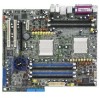
... information vii About this guide viii Typography ix K8N-DL specifications summary x Chapter 1: Product introduction 1.1 Welcome 1-1 1.2 Package contents 1-1 1.3 Special features 1-2 1.3.1 Product highlights 1-2 1.3.2 Innovative ASUS features 1-4 Chapter 2: Hardware information 2.1 Before you proceed 2-1 2.2 Motherboard overview 2-3 2.2.1 Placement direction 2-3 2.2.2 Screw holes 2-3 2.2.3 Motherboard layout 2-4 2.2.4 Layout Contents 2-5 2.3.2 Installing the CPU 2-7 2.3 Central Processing Unit (CPU 2-7 2.3.1 Overview 2-7 2.3.3 Installing the heatsink and fan 2-9 2.4 System...
... information vii About this guide viii Typography ix K8N-DL specifications summary x Chapter 1: Product introduction 1.1 Welcome 1-1 1.2 Package contents 1-1 1.3 Special features 1-2 1.3.1 Product highlights 1-2 1.3.2 Innovative ASUS features 1-4 Chapter 2: Hardware information 2.1 Before you proceed 2-1 2.2 Motherboard overview 2-3 2.2.1 Placement direction 2-3 2.2.2 Screw holes 2-3 2.2.3 Motherboard layout 2-4 2.2.4 Layout Contents 2-5 2.3.2 Installing the CPU 2-7 2.3 Central Processing Unit (CPU 2-7 2.3.1 Overview 2-7 2.3.3 Installing the heatsink and fan 2-9 2.4 System...
User Guide
Page 5
Contents 4.4 Advanced menu 4-20 4.4.1 CPU Configuration 4-20 4.4.2 Memory Configuration 4-21 4.4.3 Chipset 4-23 4.4.4 Onboard Device 4-26 4.4.5 PCIPnP 4-30 4.4.6 USB Configuration 4-32 4.5 Power menu 4-33 4.5.1 APM Configuration 4-34 4.5.2 Hardware Monitor 4-36 4.6 Boot menu 4-39 4.6.1 Boot Device Priority 4-39 4.6.2 Hard Disk Boot Priority 4-40 4.6.3 Removable Device Priority 4-40 4.6.4 Boot Settings Configuration 4-41 4.6.5 Security 4-43 4.7 Exit menu 4-45 Appendix: Reference information A.1 K8N-DL block diagram A-1 v
Contents 4.4 Advanced menu 4-20 4.4.1 CPU Configuration 4-20 4.4.2 Memory Configuration 4-21 4.4.3 Chipset 4-23 4.4.4 Onboard Device 4-26 4.4.5 PCIPnP 4-30 4.4.6 USB Configuration 4-32 4.5 Power menu 4-33 4.5.1 APM Configuration 4-34 4.5.2 Hardware Monitor 4-36 4.6 Boot menu 4-39 4.6.1 Boot Device Priority 4-39 4.6.2 Hard Disk Boot Priority 4-40 4.6.3 Removable Device Priority 4-40 4.6.4 Boot Settings Configuration 4-41 4.6.5 Security 4-43 4.7 Exit menu 4-45 Appendix: Reference information A.1 K8N-DL block diagram A-1 v
User Guide
Page 10
... features ASUS Post Reporter™ ASUS EZFlash ASUS Smart Fan Technology ASUS CrashFree BIOS 2 ASUS MyLogo2 (continued on this motherboard due to 4 GB DDR availability) 1 x PCI Express x16 slot 1 x PCI Express x1 slot 2 x PCI slots NVIDIA® CK8-04 Professional chipset supports: - 2 x Ultra DMA 133/100/66/33 - 4 x SATA-II 3Gb/s drives - K8N-DL specifications summary CPU Chipset...
... features ASUS Post Reporter™ ASUS EZFlash ASUS Smart Fan Technology ASUS CrashFree BIOS 2 ASUS MyLogo2 (continued on this motherboard due to 4 GB DDR availability) 1 x PCI Express x16 slot 1 x PCI Express x1 slot 2 x PCI slots NVIDIA® CK8-04 Professional chipset supports: - 2 x Ultra DMA 133/100/66/33 - 4 x SATA-II 3Gb/s drives - K8N-DL specifications summary CPU Chipset...
User Guide
Page 11
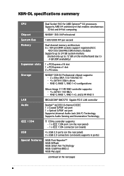
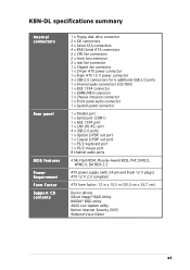
K8N-DL specifications summary Internal connectors Rear panel BIOS features Power Requirement Form Factor Support CD contents 1 x Floppy disk drive connector 2 x IDE connectors 4 x Serial ATA connectors 4 x RAID Serial ATA connectors 2 x CPU fan connectors 2 x front fan connector 2 x rear fan connector 1 x Chipset fan connector 1 x 24-pin ATX power connector 1 x 8-pin ATX 12 V power ... ATX form factor: 12 in x 10.5 in (30.5 cm x 26.7 cm) Device drivers Silicon Image® RAID Utility NVIDIA® RAID utility ASUS Live Update utility Norton Internet Security 2005 Winbond Voice Editor xi
K8N-DL specifications summary Internal connectors Rear panel BIOS features Power Requirement Form Factor Support CD contents 1 x Floppy disk drive connector 2 x IDE connectors 4 x Serial ATA connectors 4 x RAID Serial ATA connectors 2 x CPU fan connectors 2 x front fan connector 2 x rear fan connector 1 x Chipset fan connector 1 x 24-pin ATX power connector 1 x 8-pin ATX 12 V power ... ATX form factor: 12 in x 10.5 in (30.5 cm x 26.7 cm) Device drivers Silicon Image® RAID Utility NVIDIA® RAID utility ASUS Live Update utility Norton Internet Security 2005 Winbond Voice Editor xi
User Guide
Page 18
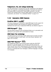
...original BIOS data from the support CD in case when the BIOS codes and data are corrupted. Temperature, fan, and voltage monitoring The CPU temperature is monitored for critical components. The system fan rotations per minute (RPM) is monitored by the ASIC (integrated in the Winbond... Super I/O) to buy a replacement ROM chip. See details on page 4-37. 1.3.2 Innovative ASUS features CrashFree BIOS 2 This feature allows you of the system boot status and causes of current for timely failure detection. This protection eliminates the...
...original BIOS data from the support CD in case when the BIOS codes and data are corrupted. Temperature, fan, and voltage monitoring The CPU temperature is monitored for critical components. The system fan rotations per minute (RPM) is monitored by the ASIC (integrated in the Winbond... Super I/O) to buy a replacement ROM chip. See details on page 4-37. 1.3.2 Innovative ASUS features CrashFree BIOS 2 This feature allows you of the system boot status and causes of current for timely failure detection. This protection eliminates the...
User Guide
Page 20
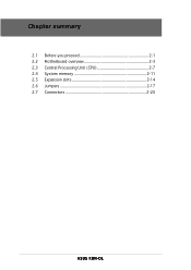
Chapter summary 2.1 Before you proceed 2-1 2.2 Motherboard overview 2-3 2.3 Central Processing Unit (CPU 2-7 2.4 System memory 2-11 2.5 Expansion slots 2-14 2.6 Jumpers 2-17 2.7 Connectors 2-20 ASUS K8N-DL
Chapter summary 2.1 Before you proceed 2-1 2.2 Motherboard overview 2-3 2.3 Central Processing Unit (CPU 2-7 2.4 System memory 2-11 2.5 Expansion slots 2-14 2.6 Jumpers 2-17 2.7 Connectors 2-20 ASUS K8N-DL
User Guide
Page 22
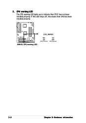
CPU warning LED The CPU warning LED lights up to indicate that CPU has been installed properly. CPU_WARN1 ® K8N-DL K8N-DL CPU warning LED ON CPU1 install fail OFF CPU install well 2-2 Chapter 2: Hardware information 2. If this LED stays off, this means that CPU1 has not been installed properly.
CPU warning LED The CPU warning LED lights up to indicate that CPU has been installed properly. CPU_WARN1 ® K8N-DL K8N-DL CPU warning LED ON CPU1 install fail OFF CPU install well 2-2 Chapter 2: Hardware information 2. If this LED stays off, this means that CPU1 has not been installed properly.
User Guide
Page 25
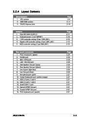
CPU sockets 2. LAN 1 (RJ-45) port 5. Line Out port (lime) 9. DDR DIMM sockets 3. Gigabit LAN controller setting (3-pin LAN1_EN1) 5. USB 2.0 ports 3 and 4 12. USB 2.0 ports 1 and 2 ... 2-6 2-11 2-16 Page 2-17 2-18 2-18 2-19 2-19 Page 2-20 2-20 2-20 2-20 2-20 2-20 2-20 2-20 2-21 2-21 2-21 2-21 2-21 2-21 2-21 2-21 ASUS K8N-DL 2-5 Keyboard power (3-pin KBPWR1) 3. 1394 controller setting (3-pin 1394_EN1) 4. Rear Speaker Out port (black) 7. Serial (COM 1) port 14. PCI/PCI Express slots Jumpers 1. Microphone port...
CPU sockets 2. LAN 1 (RJ-45) port 5. Line Out port (lime) 9. DDR DIMM sockets 3. Gigabit LAN controller setting (3-pin LAN1_EN1) 5. USB 2.0 ports 3 and 4 12. USB 2.0 ports 1 and 2 ... 2-6 2-11 2-16 Page 2-17 2-18 2-18 2-19 2-19 Page 2-20 2-20 2-20 2-20 2-20 2-20 2-20 2-20 2-21 2-21 2-21 2-21 2-21 2-21 2-21 2-21 ASUS K8N-DL 2-5 Keyboard power (3-pin KBPWR1) 3. 1394 controller setting (3-pin 1394_EN1) 4. Rear Speaker Out port (black) 7. Serial (COM 1) port 14. PCI/PCI Express slots Jumpers 1. Microphone port...
User Guide
Page 27
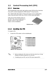
ASUS K8N-DL 2-7 2.3 Central Processing Unit (CPU) 2.3.1 Overview The motherboard comes with only 32-bit or 64-bit wide data paths. This corner should match a specific corner on your left. • If installing only one CPU, use the CPU socket marked CPU1. CPU2 CPU1 ® K8N-DL K8N-DL CPU Socket 940 • Before installing the CPU, make sure that the socket box...
ASUS K8N-DL 2-7 2.3 Central Processing Unit (CPU) 2.3.1 Overview The motherboard comes with only 32-bit or 64-bit wide data paths. This corner should match a specific corner on your left. • If installing only one CPU, use the CPU socket marked CPU1. CPU2 CPU1 ® K8N-DL K8N-DL CPU Socket 940 • Before installing the CPU, make sure that the socket box...

User Guide
Page 28
... the lever sideways, then lift it is locked. 2-8 Chapter 2: Hardware information Triangle mark Notched corner The CPU fits only in place. Carefully insert the CPU into the socket to prevent bending the pins and damaging the CPU! 5. The lever clicks on the side tab to indicate that it up to 90°-100...° angle, otherwise the CPU does not fit in place, push down the socket lever to a 90°-100° angle. DO NOT force the CPU into the socket until it fits in one correct orientation. Socket Lever Make sure that...
... the lever sideways, then lift it is locked. 2-8 Chapter 2: Hardware information Triangle mark Notched corner The CPU fits only in place. Carefully insert the CPU into the socket to prevent bending the pins and damaging the CPU! 5. The lever clicks on the side tab to indicate that it up to 90°-100...° angle, otherwise the CPU does not fit in place, push down the socket lever to a 90°-100° angle. DO NOT force the CPU into the socket until it fits in one correct orientation. Socket Lever Make sure that...
User Guide
Page 29
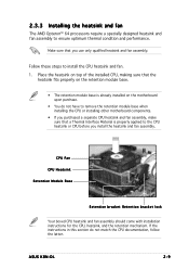
... • You do not match the CPU documentation, follow the latter. If the instructions in this section do not have to the CPU heatsink or CPU before you use only qualified heatsink and fan assembly. CPU Fan CPU Heatsink Retention Module Base Retention bracket Retention ... to remove the retention module base when installing the CPU or installing other motherboard components. • If you purchased a separate CPU heatsink and fan assembly, make sure that you install the heatsink and fan assembly. ASUS K8N-DL 2-9 Follow these steps to ensure optimum thermal condition and...
... • You do not match the CPU documentation, follow the latter. If the instructions in this section do not have to the CPU heatsink or CPU before you use only qualified heatsink and fan assembly. CPU Fan CPU Heatsink Retention Module Base Retention bracket Retention ... to remove the retention module base when installing the CPU or installing other motherboard components. • If you purchased a separate CPU heatsink and fan assembly, make sure that you install the heatsink and fan assembly. ASUS K8N-DL 2-9 Follow these steps to ensure optimum thermal condition and...
User Guide
Page 31
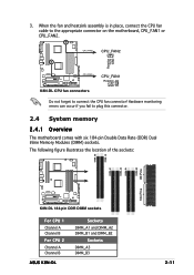
3. The following figure illustrates the location of the sockets: DIMM_A3 DIMM_B3 DIMM_B2 80 Pins DIMM_A2 DIMM_B1 DIMM_A1 104 Pins ® K8N-DL K8N-DL 184-pin DDR DIMM sockets For CPU 1 Channel A Channel B For CPU 2 Channel A Channel B ASUS K8N-DL Sockets DIMM_A1 and DIMM_A2 DIMM_B1 and DIMM_B2 Sockets DIMM_A3 DIMM_B3 2-11 Hardware monitoring errors can occur if you fail to...
3. The following figure illustrates the location of the sockets: DIMM_A3 DIMM_B3 DIMM_B2 80 Pins DIMM_A2 DIMM_B1 DIMM_A1 104 Pins ® K8N-DL K8N-DL 184-pin DDR DIMM sockets For CPU 1 Channel A Channel B For CPU 2 Channel A Channel B ASUS K8N-DL Sockets DIMM_A1 and DIMM_A2 DIMM_B1 and DIMM_B2 Sockets DIMM_A3 DIMM_B3 2-11 Hardware monitoring errors can occur if you fail to...

User Guide
Page 32
Refer to the DDR400 Qualified Vendors List on the next page for better performance. Single CPU: DIMM_A1+DIMM_A2=DIMM_B1+DIMM_B2 Dual CPU: DIMM_A1+DIMM_A2=DIMM_B1+DIMM_B2=DIMM_A3+DIMM_B3 • When using one DDR DIMM module, install into DIMM_A1 slot only. • When using two DDR DIMM modules, ...
Refer to the DDR400 Qualified Vendors List on the next page for better performance. Single CPU: DIMM_A1+DIMM_A2=DIMM_B1+DIMM_B2 Dual CPU: DIMM_A1+DIMM_A2=DIMM_B1+DIMM_B2=DIMM_A3+DIMM_B3 • When using one DDR DIMM module, install into DIMM_A1 slot only. • When using two DDR DIMM modules, ...
User Guide
Page 37
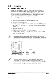
... system failure due to pins 2-3. Move the jumper cap from pins 1-2 (default) to overclocking, use the C.P.R. (CPU Parameter Recall) feature. Keep the cap on CLRTC jumper default position. ASUS K8N-DL 2-17 You can automatically reset parameter settings to pins 1-2. 4. Except when clearing the RTC RAM, never remove the ...battery powers the RAM data in CMOS. To erase the RTC RAM: 1. Removing the cap will cause system boot failure! ® K8N-DL K8N-DL Clear RTC RAM CLRTC1 12 23 Normal (Default) Clear CMOS You do not need to clear the RTC when the system hangs due to...
... system failure due to pins 2-3. Move the jumper cap from pins 1-2 (default) to overclocking, use the C.P.R. (CPU Parameter Recall) feature. Keep the cap on CLRTC jumper default position. ASUS K8N-DL 2-17 You can automatically reset parameter settings to pins 1-2. 4. Except when clearing the RTC RAM, never remove the ...battery powers the RAM data in CMOS. To erase the RTC RAM: 1. Removing the cap will cause system boot failure! ® K8N-DL K8N-DL Clear RTC RAM CLRTC1 12 23 Normal (Default) Clear CMOS You do not need to clear the RTC when the system hangs due to...

User Guide
Page 39
... controller. Set to pins 1-2 to activate the Gigabit LAN feature. ® K8N-DL LAN1_EN1 2 1 Enable (Default) 3 2 Disable K8N-DL CPU LAN1_EN setting 5 . Gigabit LAN controller setting (3-pin LAN1_EN1) This jumper allows you to enable or disable the onboard Broadcom® BCM5751 Gigabit LAN1 controller. RAID_EN1 ® K8N-DL 12 Enable (Default) 23 Disable K8N-DL RAID controller setting ASUS K8N-DL 2-19 4 .
... controller. Set to pins 1-2 to activate the Gigabit LAN feature. ® K8N-DL LAN1_EN1 2 1 Enable (Default) 3 2 Disable K8N-DL CPU LAN1_EN setting 5 . Gigabit LAN controller setting (3-pin LAN1_EN1) This jumper allows you to enable or disable the onboard Broadcom® BCM5751 Gigabit LAN1 controller. RAID_EN1 ® K8N-DL 12 Enable (Default) 23 Disable K8N-DL RAID controller setting ASUS K8N-DL 2-19 4 .
User Guide
Page 45
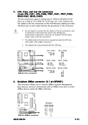
... to the fan connectors on the fan connectors! • The ASUS Smart Q-Fan function is supported using the CPU fans (CPU_FAN1, CPU_FAN2) connectors. • The chipset fan is synchronized with an SMBus host and /or other SMBus devices using the SMBus interface. ® K8N-DL K8N-DL SMBus connector ASUS K8N-DL BPSMB1 1 FAN_PWM I2C_4_CLK# GND I2C_4_DATA# +5VSB 2-25
... to the fan connectors on the fan connectors! • The ASUS Smart Q-Fan function is supported using the CPU fans (CPU_FAN1, CPU_FAN2) connectors. • The chipset fan is synchronized with an SMBus host and /or other SMBus devices using the SMBus interface. ® K8N-DL K8N-DL SMBus connector ASUS K8N-DL BPSMB1 1 FAN_PWM I2C_4_CLK# GND I2C_4_DATA# +5VSB 2-25
User Guide
Page 55
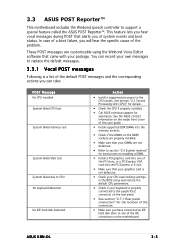
... your DIMMs are properly installed. • Make sure that alerts you will hear the specific cause of system events and boot status. ASUS K8N-DL 3-3 In case of a boot failure, you of the problem. This feature lets you hear vocal messages during POST that your package....Install a PCI graphics card into one of the IDE connectors on the motherboard. See section "2.3 Central Processing Unit (CPU)" for details. • Check the CPU if properly installed. • Call ASUS technical support for the location of the PCI slots, or a PCI Express VGA card into the memory sockets. ...
... your DIMMs are properly installed. • Make sure that alerts you will hear the specific cause of system events and boot status. ASUS K8N-DL 3-3 In case of a boot failure, you of the problem. This feature lets you hear vocal messages during POST that your package....Install a PCI graphics card into one of the IDE connectors on the motherboard. See section "2.3 Central Processing Unit (CPU)" for details. • Check the CPU if properly installed. • Call ASUS technical support for the location of the PCI slots, or a PCI Express VGA card into the memory sockets. ...

User Guide
Page 56
... it is working properly. • Check the CPU fan and make sure it turns on the inside front cover of range Computer now booting from operating system Action • Check if the CPU fan is not defective. • Call ASUS technical support for details. 3-4 Chapter 3: Powering ...up POST Message CPU temperature too high CPU fan failed CPU voltage out of this user guide. • No action required You can...
... it is working properly. • Check the CPU fan and make sure it turns on the inside front cover of range Computer now booting from operating system Action • Check if the CPU fan is not defective. • Call ASUS technical support for details. 3-4 Chapter 3: Powering ...up POST Message CPU temperature too high CPU fan failed CPU voltage out of this user guide. • No action required You can...
User Guide
Page 82
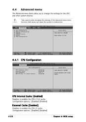
...items. Incorrect field values can cause the system to change the settings for the CPU and other system devices. Configuration options: [Disabled] [Enabled] External Cache [Enabled] Disables or enables the CPU L3 cache. F1:Help ESC: Exit ↑↓ : Select Item →...Select Menu -/+: Change Value Enter: Select Sub-menu F5: Setup Defaults F10: Save and Exit 4.4.1 CPU Configuration Advanced Phoenix-Award BIOS CMOS Setup Utility CPU Configuration CPU Internal Cache External Cache CPU Frequency AMD K8 Cool 'n' Quiet Control [Enabled] [Enabled] [200.0] [Enabled] Select Menu Item ...
...items. Incorrect field values can cause the system to change the settings for the CPU and other system devices. Configuration options: [Disabled] [Enabled] External Cache [Enabled] Disables or enables the CPU L3 cache. F1:Help ESC: Exit ↑↓ : Select Item →...Select Menu -/+: Change Value Enter: Select Sub-menu F5: Setup Defaults F10: Save and Exit 4.4.1 CPU Configuration Advanced Phoenix-Award BIOS CMOS Setup Utility CPU Configuration CPU Internal Cache External Cache CPU Frequency AMD K8 Cool 'n' Quiet Control [Enabled] [Enabled] [200.0] [Enabled] Select Menu Item ...
User Guide
Page 83
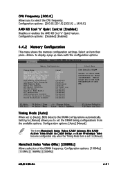
...(Mhz) [200MHz] Allows selection of the DRAM frequency. CPU Frequency [200.0] Allows you to set the DRAM timing ...a t e n c y, M i n R A S # A c t i v e T i m e, R A S # t o C A S # D e l a y, and R o w P r e c h a r g e T i m e become configurable only when the Timing Mode item is set to set each configuration on your own. Configuration options: [100Mhz] [133Mhz] [166Mhz] [200Mhz] ASUS K8N-DL 4-21 Setting to [Manual] allows you to [Auto], BIOS detects the DRAM configurations automatically. Configuration options: [Disabled] [Enabled] 4.4.2 Memory Configuration This menu shows the memory...
...(Mhz) [200MHz] Allows selection of the DRAM frequency. CPU Frequency [200.0] Allows you to set the DRAM timing ...a t e n c y, M i n R A S # A c t i v e T i m e, R A S # t o C A S # D e l a y, and R o w P r e c h a r g e T i m e become configurable only when the Timing Mode item is set to set each configuration on your own. Configuration options: [100Mhz] [133Mhz] [166Mhz] [200Mhz] ASUS K8N-DL 4-21 Setting to [Manual] allows you to [Auto], BIOS detects the DRAM configurations automatically. Configuration options: [Disabled] [Enabled] 4.4.2 Memory Configuration This menu shows the memory...


