User Guide
Page 15
..., and hardware devices on it another standout in your package with the list below. 1.2 Package contents Check your retailer. ASUS K8N-DL 1-1 The motherboard delivers a host of new features and latest technologies, making it , check the items in the long ... of the above items is damaged or missing, contact your motherboard package for buying an ASUS® K8N-DL motherboard! Before you for the following items. Motherboard I/O modules Cables Accessories Application CD Documentation ASUS K8N-DL motherboard IEEE1394 (1 port) module USB 2.0 + GAME port module 4 x Serial ATA ...
..., and hardware devices on it another standout in your package with the list below. 1.2 Package contents Check your retailer. ASUS K8N-DL 1-1 The motherboard delivers a host of new features and latest technologies, making it , check the items in the long ... of the above items is damaged or missing, contact your motherboard package for buying an ASUS® K8N-DL motherboard! Before you for the following items. Motherboard I/O modules Cables Accessories Application CD Documentation ASUS K8N-DL motherboard IEEE1394 (1 port) module USB 2.0 + GAME port module 4 x Serial ATA ...
User Guide
Page 17
.... IEEE 1394a support The IEEE 1394a interface provides high-speed and flexible PC connectivity to a wide range of peripherals and devices compliant to support RAID 5. ASUS K8N-DL 1-3 See pages2-21 for details. The S/PDIF technology turns your computer into a high-end entertainment system with dual-RAID functionality that allows you to select...
.... IEEE 1394a support The IEEE 1394a interface provides high-speed and flexible PC connectivity to a wide range of peripherals and devices compliant to support RAID 5. ASUS K8N-DL 1-3 See pages2-21 for details. The S/PDIF technology turns your computer into a high-end entertainment system with dual-RAID functionality that allows you to select...
User Guide
Page 20
Chapter summary 2.1 Before you proceed 2-1 2.2 Motherboard overview 2-3 2.3 Central Processing Unit (CPU 2-7 2.4 System memory 2-11 2.5 Expansion slots 2-14 2.6 Jumpers 2-17 2.7 Connectors 2-20 ASUS K8N-DL
Chapter summary 2.1 Before you proceed 2-1 2.2 Motherboard overview 2-3 2.3 Central Processing Unit (CPU 2-7 2.4 System memory 2-11 2.5 Expansion slots 2-14 2.6 Jumpers 2-17 2.7 Connectors 2-20 ASUS K8N-DL
User Guide
Page 21
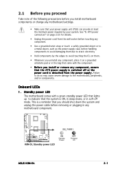
... LEDs 1. Failure to do so may cause severe damage to static electricity • Hold components by your system. SB_PWR1 ® K8N-DL K8N-DL Standby power LED ON Standby Power OFF Powered Off ASUS K8N-DL 2-1 Standby power LED The motherboard comes with a green standby power LED that lights up to indicate that the system is a reminder...
... LEDs 1. Failure to do so may cause severe damage to static electricity • Hold components by your system. SB_PWR1 ® K8N-DL K8N-DL Standby power LED ON Standby Power OFF Powered Off ASUS K8N-DL 2-1 Standby power LED The motherboard comes with a green standby power LED that lights up to indicate that the system is a reminder...
User Guide
Page 23
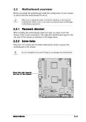
... to secure the motherboard to do so can damage the motherboard. Failure to the chassis. Make sure to the rear part of the chassis ® K8N-DL ASUS K8N-DL 2-3 Place this side towards the rear of the chassis as indicated in the image below. 2.2.2 Screw holes Place ten (10) screws into it into the...
... to secure the motherboard to do so can damage the motherboard. Failure to the chassis. Make sure to the rear part of the chassis ® K8N-DL ASUS K8N-DL 2-3 Place this side towards the rear of the chassis as indicated in the image below. 2.2.2 Screw holes Place ten (10) screws into it into the...
User Guide
Page 25
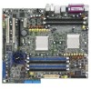
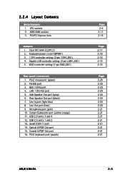
... 2-6 2-11 2-16 Page 2-17 2-18 2-18 2-19 2-19 Page 2-20 2-20 2-20 2-20 2-20 2-20 2-20 2-20 2-21 2-21 2-21 2-21 2-21 2-21 2-21 2-21 ASUS K8N-DL 2-5 PCI/PCI Express slots Jumpers 1. IEEE 1394a port 4. Line In port (light blue) 8. USB 2.0 ports 3 and 4 12. USB 2.0 ports 1 and 2 13. 2.2.4 Layout Contents Slots/Sockets...
... 2-6 2-11 2-16 Page 2-17 2-18 2-18 2-19 2-19 Page 2-20 2-20 2-20 2-20 2-20 2-20 2-20 2-20 2-21 2-21 2-21 2-21 2-21 2-21 2-21 2-21 ASUS K8N-DL 2-5 PCI/PCI Express slots Jumpers 1. IEEE 1394a port 4. Line In port (light blue) 8. USB 2.0 ports 3 and 4 12. USB 2.0 ports 1 and 2 13. 2.2.4 Layout Contents Slots/Sockets...
User Guide
Page 27
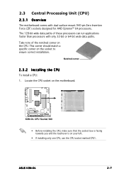
... Socket 940 • Before installing the CPU, make sure that the socket box is facing towards you and the load lever is on the motherboard. ASUS K8N-DL 2-7 Take note of these processors can run applications faster than processors with dual surface mount 940-pin Zero Insertion Force (ZIF) sockets designed for AMD...
... Socket 940 • Before installing the CPU, make sure that the socket box is facing towards you and the load lever is on the motherboard. ASUS K8N-DL 2-7 Take note of these processors can run applications faster than processors with dual surface mount 940-pin Zero Insertion Force (ZIF) sockets designed for AMD...
User Guide
Page 29
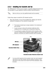
Follow these steps to ensure optimum thermal condition and performance. ASUS K8N-DL 2-9 CPU Fan CPU Heatsink Retention Module Base Retention bracket Retention bracket lock Your boxed CPU heatsink and fan assembly should come with installation instructions for ...
Follow these steps to ensure optimum thermal condition and performance. ASUS K8N-DL 2-9 CPU Fan CPU Heatsink Retention Module Base Retention bracket Retention bracket lock Your boxed CPU heatsink and fan assembly should come with installation instructions for ...
User Guide
Page 31
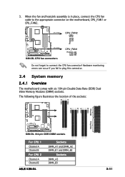
CPU_FAN2 CPU_FAN2 Rotation +12V GND ® K8N-DL CPU_FAN1 K8N-DL CPU fan connectors CPU_FAN1 Rotation +12V GND Do not forget to plug this connector. 2.4 System memory 2.4.1 Overview The motherboard comes with six 184-..., CPU_FAN1 or CPU_FAN2. The following figure illustrates the location of the sockets: DIMM_A3 DIMM_B3 DIMM_B2 80 Pins DIMM_A2 DIMM_B1 DIMM_A1 104 Pins ® K8N-DL K8N-DL 184-pin DDR DIMM sockets For CPU 1 Channel A Channel B For CPU 2 Channel A Channel B ASUS K8N-DL Sockets DIMM_A1 and DIMM_A2 DIMM_B1 and DIMM_B2 Sockets DIMM_A3 DIMM_B3 2-11 3.
CPU_FAN2 CPU_FAN2 Rotation +12V GND ® K8N-DL CPU_FAN1 K8N-DL CPU fan connectors CPU_FAN1 Rotation +12V GND Do not forget to plug this connector. 2.4 System memory 2.4.1 Overview The motherboard comes with six 184-..., CPU_FAN1 or CPU_FAN2. The following figure illustrates the location of the sockets: DIMM_A3 DIMM_B3 DIMM_B2 80 Pins DIMM_A2 DIMM_B1 DIMM_A1 104 Pins ® K8N-DL K8N-DL 184-pin DDR DIMM sockets For CPU 1 Channel A Channel B For CPU 2 Channel A Channel B ASUS K8N-DL Sockets DIMM_A1 and DIMM_A2 DIMM_B1 and DIMM_B2 Sockets DIMM_A3 DIMM_B3 2-11 3.
User Guide
Page 33
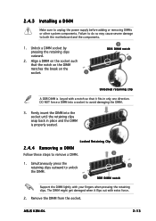
Remove the DIMM from the socket. ASUS K8N-DL 2-13 Unlock a DIMM socket by pressing the retaining clips outward. 2. Locked Retaining Clip 2.4.4 Removing a DIMM Follow these steps to both the motherboard and the components. 1. ...
Remove the DIMM from the socket. ASUS K8N-DL 2-13 Unlock a DIMM socket by pressing the retaining clips outward. 2. Locked Retaining Clip 2.4.4 Removing a DIMM Follow these steps to both the motherboard and the components. 1. ...
User Guide
Page 35
ASUS K8N-DL 2-15 2.5.3 Interrupt assignments Standard interrupt assignments IRQ Priority 0 1 1 2 2 - 4 12 5 13 6 14 7 15 8 3 9 4 10 5 11 6 12 7 13 8 14 9 15 10 Standard Function System Timer Keyboard Controller ...
ASUS K8N-DL 2-15 2.5.3 Interrupt assignments Standard interrupt assignments IRQ Priority 0 1 1 2 2 - 4 12 5 13 6 14 7 15 8 3 9 4 10 5 11 6 12 7 13 8 14 9 15 10 Standard Function System Timer Keyboard Controller ...
User Guide
Page 37
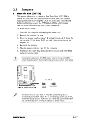
... never remove the cap on pins 2-3 for about 5~10 seconds, then move the cap back to overclocking, use the C.P.R. (CPU Parameter Recall) feature. ASUS K8N-DL 2-17 Clear RTC RAM (CLRTC1) This jumper allows you to pins 2-3. Move the jumper cap from pins 1-2 (default) to clear the Real Time Clock ... default position. Remove the onboard battery. 3. For system failure due to pins 1-2. 4. Removing the cap will cause system boot failure! ® K8N-DL K8N-DL Clear RTC RAM CLRTC1 12 23 Normal (Default) Clear CMOS You do not need to clear the RTC when the system hangs due to re...
... never remove the cap on pins 2-3 for about 5~10 seconds, then move the cap back to overclocking, use the C.P.R. (CPU Parameter Recall) feature. ASUS K8N-DL 2-17 Clear RTC RAM (CLRTC1) This jumper allows you to pins 2-3. Move the jumper cap from pins 1-2 (default) to clear the Real Time Clock ... default position. Remove the onboard battery. 3. For system failure due to pins 1-2. 4. Removing the cap will cause system boot failure! ® K8N-DL K8N-DL Clear RTC RAM CLRTC1 12 23 Normal (Default) Clear CMOS You do not need to clear the RTC when the system hangs due to re...

User Guide
Page 39
RAID_EN1 ® K8N-DL 12 Enable (Default) 23 Disable K8N-DL RAID controller setting ASUS K8N-DL 2-19 Gigabit LAN controller setting (3-pin LAN1_EN1) This jumper allows you to activate the RAID feature. Set to pins 1-2 to enable or disable the onboard ... disable the onboard Silicon Image® 3114R RAID controller. RAID controller setting (3-pin RAID_EN1) This jumper allows you to activate the Gigabit LAN feature. ® K8N-DL LAN1_EN1 2 1 Enable (Default) 3 2 Disable K8N-DL CPU LAN1_EN setting 5 . 4 .
RAID_EN1 ® K8N-DL 12 Enable (Default) 23 Disable K8N-DL RAID controller setting ASUS K8N-DL 2-19 Gigabit LAN controller setting (3-pin LAN1_EN1) This jumper allows you to activate the RAID feature. Set to pins 1-2 to enable or disable the onboard ... disable the onboard Silicon Image® 3114R RAID controller. RAID controller setting (3-pin RAID_EN1) This jumper allows you to activate the Gigabit LAN feature. ® K8N-DL LAN1_EN1 2 1 Enable (Default) 3 2 Disable K8N-DL CPU LAN1_EN setting 5 . 4 .

User Guide
Page 41
... Universal Serial Bus (USB) ports are available for connecting USB 2.0 devices. 1 3 . U S B 2 . 0 p o r t s 1 a n d 2 . C o a x i a l S / P D I F O u t p o r t. This port is for the function of the audio ports in 2, 4, 6, or 8-channel configuration. ASUS K8N-DL 2-21 Audio 2, 4, 6, or 8-channel configuration Port Light Blue Lime Pink Black Gray Yellow Orange Headset 2-channel Line In Line Out Mic In • • •...
... Universal Serial Bus (USB) ports are available for connecting USB 2.0 devices. 1 3 . U S B 2 . 0 p o r t s 1 a n d 2 . C o a x i a l S / P D I F O u t p o r t. This port is for the function of the audio ports in 2, 4, 6, or 8-channel configuration. ASUS K8N-DL 2-21 Audio 2, 4, 6, or 8-channel configuration Port Light Blue Lime Pink Black Gray Yellow Orange Headset 2-channel Line In Line Out Mic In • • •...

User Guide
Page 43
ASUS K8N-DL 2-23 Serial ATA connectors (7-pin SATA1, SATA2, SATA3, SATA4) Supported by the NVIDIA® nForce4™ chipset, these connectors are for the Serial ATA signal ... up to install the Serial ATA extension module. SATA1 SATA2 GND RSATA_TXP1 RSATA_TXN1 GND RSATA_RXN1 RSATA_RXP1 GND GND RSATA_TXP2 RSATA_TXN2 GND RSATA_RXN2 RSATA_RXP2 GND ® K8N-DL K8N-DL SATA connectors SATA3 SATA4 GND RSATA_TXP3 RSATA_TXN3 GND RSATA_RXN3 RSATA_RXP3 GND GND RSATA_TXP4 RSATA_TXN4 GND RSATA_RXN4 RSATA_RXP4 GND Important notes on Serial ATA • The...
ASUS K8N-DL 2-23 Serial ATA connectors (7-pin SATA1, SATA2, SATA3, SATA4) Supported by the NVIDIA® nForce4™ chipset, these connectors are for the Serial ATA signal ... up to install the Serial ATA extension module. SATA1 SATA2 GND RSATA_TXP1 RSATA_TXN1 GND RSATA_RXN1 RSATA_RXP1 GND GND RSATA_TXP2 RSATA_TXN2 GND RSATA_RXN2 RSATA_RXP2 GND ® K8N-DL K8N-DL SATA connectors SATA3 SATA4 GND RSATA_TXP3 RSATA_TXN3 GND RSATA_RXN3 RSATA_RXP3 GND GND RSATA_TXP4 RSATA_TXN4 GND RSATA_RXN4 RSATA_RXP4 GND Important notes on Serial ATA • The...
User Guide
Page 45
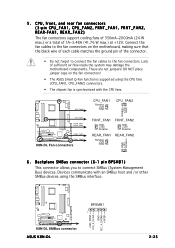
...forget to connect the fan cables to connect SMBus (System Management Bus) devices. CPU_FAN2 CPU_FAN1 REAR_FAN1 REAR_FAN2 ® K8N-DL FRNT_FAN1 FRNT_FAN2 K8N-DL Fan connectors CPU_FAN1 Rotation +12V GND CPU_FAN2 Rotation +12V GND FRNT_FAN1 GND +12V Rotation FRNT_FAN2 GND +12V Rotation ... • The ASUS Smart Q-Fan function is supported using the CPU fans (CPU_FAN1, CPU_FAN2) connectors. • The chipset fan is synchronized with an SMBus host and /or other SMBus devices using the SMBus interface. ® K8N-DL K8N-DL SMBus connector ASUS K8N-DL BPSMB1 1 FAN_PWM I2C_4_CLK...
...forget to connect the fan cables to connect SMBus (System Management Bus) devices. CPU_FAN2 CPU_FAN1 REAR_FAN1 REAR_FAN2 ® K8N-DL FRNT_FAN1 FRNT_FAN2 K8N-DL Fan connectors CPU_FAN1 Rotation +12V GND CPU_FAN2 Rotation +12V GND FRNT_FAN1 GND +12V Rotation FRNT_FAN2 GND +12V Rotation ... • The ASUS Smart Q-Fan function is supported using the CPU fans (CPU_FAN1, CPU_FAN2) connectors. • The chipset fan is synchronized with an SMBus host and /or other SMBus devices using the SMBus interface. ® K8N-DL K8N-DL SMBus connector ASUS K8N-DL BPSMB1 1 FAN_PWM I2C_4_CLK...
User Guide
Page 47
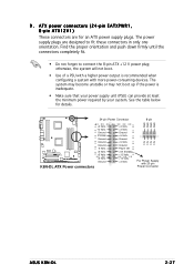
... The power supply plugs are for details. 24-pin Power Connector 8-pin GND GND GND GND ® K8N-DL +3 Volts -12 Volts Ground PSON# Ground Ground Ground -5 Volts +5 Volts +5 Volts +5 Volts Ground K8N-DL ATX Power connectors +3 Volts +3 Volts Ground +5 Volts Ground +5 Volts Ground Power OK +5V Standby +... system may become unstable or may not boot up if the power is recommended when configuring a system with 20-pin Power Connector 12V 12V ASUS K8N-DL 2-27 9 . See the table below for an ATX power supply plugs. ATX power connectors (24-pin EATXPWR1, 8-pin ATX12V1) These ...
... The power supply plugs are for details. 24-pin Power Connector 8-pin GND GND GND GND ® K8N-DL +3 Volts -12 Volts Ground PSON# Ground Ground Ground -5 Volts +5 Volts +5 Volts +5 Volts Ground K8N-DL ATX Power connectors +3 Volts +3 Volts Ground +5 Volts Ground +5 Volts Ground Power OK +5V Standby +... system may become unstable or may not boot up if the power is recommended when configuring a system with 20-pin Power Connector 12V 12V ASUS K8N-DL 2-27 9 . See the table below for an ATX power supply plugs. ATX power connectors (24-pin EATXPWR1, 8-pin ATX12V1) These ...
User Guide
Page 49
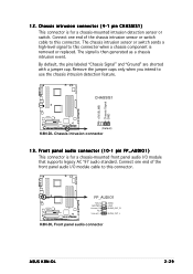
12. Chassis intrusion connector (4-1 pin CHASSIS1) This connector is removed or replaced. CHASSIS1 ® K8N-DL (Default) K8N-DL Chassis intrusion connector 13. The chassis intrusion sensor or switch sends a high-level signal to use the chassis intrusion ...-mounted front panel audio I /O module cable to this connector. +5VSB_MB Chassis Signal GND ® K8N-DL FP_AUDIO1 MIC2 MICPWR Line out_R NC Line out_L AGND +5VA BLINE_OUT_R BLINE_OUT_L K8N-DL Front panel audio connector ASUS K8N-DL 2-29 By default, the pins labeled "Chassis Signal" and "Ground" are shorted with a jumper ...
12. Chassis intrusion connector (4-1 pin CHASSIS1) This connector is removed or replaced. CHASSIS1 ® K8N-DL (Default) K8N-DL Chassis intrusion connector 13. The chassis intrusion sensor or switch sends a high-level signal to use the chassis intrusion ...-mounted front panel audio I /O module cable to this connector. +5VSB_MB Chassis Signal GND ® K8N-DL FP_AUDIO1 MIC2 MICPWR Line out_R NC Line out_L AGND +5VA BLINE_OUT_R BLINE_OUT_L K8N-DL Front panel audio connector ASUS K8N-DL 2-29 By default, the pins labeled "Chassis Signal" and "Ground" are shorted with a jumper ...
User Guide
Page 52
Chapter summary 3.1 Starting up for the first time 3-1 3.2 Powering off the computer 3-2 3.3 ASUS POST Reporter 3-3 ASUS K8N-DL
Chapter summary 3.1 Starting up for the first time 3-1 3.2 Powering off the computer 3-2 3.3 ASUS POST Reporter 3-3 ASUS K8N-DL

User Guide
Page 53
... your monitor complies with ATX power supplies, the system LED lights up or switch between orange and green after the system LED turns on test. ASUS K8N-DL 3-1 Turn on self tests or POST. If your retailer for the first time 1. For systems with "green" standards or if it has a "power standby" feature...
... your monitor complies with ATX power supplies, the system LED lights up or switch between orange and green after the system LED turns on test. ASUS K8N-DL 3-1 Turn on self tests or POST. If your retailer for the first time 1. For systems with "green" standards or if it has a "power standby" feature...


