
User Guide
Page 4
... down function 3-2 3.2.2 Using the dual function power switch 3-2 3.3 ASUS POST Reporter 3-3 3.3.1 Vocal POST messages 3-3 3.3.2 Winbond Voice Editor 3-5 Chapter 4: BIOS setup 4.1 Managing and updating your BIOS 4-1 4.1.1 Creating a bootable floppy disk 4-1 4.1.2 Updating the BIOS 4-2 4.1.3 Saving the current BIOS file 4-4 4.1.4 ASUS CrashFree BIOS 2 utility 4-5 4.1.5 ASUS EZ Flash utility 4-7 4.1.6 ASUS Update utility 4-8 4.2 BIOS setup program 4-11 4.2.1 BIOS menu screen 4-12 4.2.2 Menu bar 4-12 4.2.3 Legend bar...
... down function 3-2 3.2.2 Using the dual function power switch 3-2 3.3 ASUS POST Reporter 3-3 3.3.1 Vocal POST messages 3-3 3.3.2 Winbond Voice Editor 3-5 Chapter 4: BIOS setup 4.1 Managing and updating your BIOS 4-1 4.1.1 Creating a bootable floppy disk 4-1 4.1.2 Updating the BIOS 4-2 4.1.3 Saving the current BIOS file 4-4 4.1.4 ASUS CrashFree BIOS 2 utility 4-5 4.1.5 ASUS EZ Flash utility 4-7 4.1.6 ASUS Update utility 4-8 4.2 BIOS setup program 4-11 4.2.1 BIOS menu screen 4-12 4.2.2 Menu bar 4-12 4.2.3 Legend bar...
User Guide
Page 8
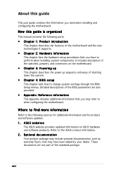
... information and for product and software updates. 1. Detailed descriptions of the BIOS parameters are not part of shutting down the system. • Chapter 4: BIOS setup This chapter tells how to perform when installing system components. Refer to the ASUS contact information. 2. ASUS websites The ASUS website provides updated information on the motherboard. • Chapter 3: Powering...
... information and for product and software updates. 1. Detailed descriptions of the BIOS parameters are not part of shutting down the system. • Chapter 4: BIOS setup This chapter tells how to perform when installing system components. Refer to the ASUS contact information. 2. ASUS websites The ASUS website provides updated information on the motherboard. • Chapter 3: Powering...
User Guide
Page 10
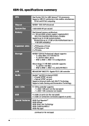
...NVIDIA® CK8-04 Professional chipset supports: - 2 x Ultra DMA 133/100/66/33 - 4 x SATA-II 3Gb/s drives - K8N-DL specifications summary CPU Chipset System Bus Memory Expansion slots Storage Dual Socket 940 for AMD Opteron™ 64 processors Supports AMD 64 architecture that enables...up to 24 GB system memory (tested only up to 12 GB on board; supports 6 ports) Special features ASUS Post Reporter™ ASUS EZFlash ASUS Smart Fan Technology ASUS CrashFree BIOS 2 ASUS MyLogo2 (continued on the next page) x RAID 0, RAID 1, RAID 1+0 configurations LAN Audio Silicon Image 3114R RAID...
...NVIDIA® CK8-04 Professional chipset supports: - 2 x Ultra DMA 133/100/66/33 - 4 x SATA-II 3Gb/s drives - K8N-DL specifications summary CPU Chipset System Bus Memory Expansion slots Storage Dual Socket 940 for AMD Opteron™ 64 processors Supports AMD 64 architecture that enables...up to 24 GB system memory (tested only up to 12 GB on board; supports 6 ports) Special features ASUS Post Reporter™ ASUS EZFlash ASUS Smart Fan Technology ASUS CrashFree BIOS 2 ASUS MyLogo2 (continued on the next page) x RAID 0, RAID 1, RAID 1+0 configurations LAN Audio Silicon Image 3114R RAID...
User Guide
Page 11
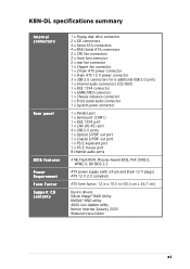
K8N-DL specifications summary Internal connectors Rear panel BIOS features Power Requirement Form Factor Support CD contents 1 x Floppy disk drive connector 2 x IDE connectors 4 x Serial ATA connectors 4 x RAID Serial ATA connectors 2 x CPU fan connectors 2 x front ... 2.0 ports 1 x Optical S/PDIF out port 1 x Coaxial S/PDIF out port 1 x PS/2 keyboard port 1 x PS/2 mouse port 8-channel audio ports 4 Mb Flash ROM, Phoenix-Award BIOS, PnP, DMI2.0, WfM2.0, SM BIOS 2.3 ATX power supply (with 24-pin and 8-pin 12 V plugs) ATX 12 V 2.0 compliant ATX form factor: 12 in x 10.5 in (30.5 cm x 26...
K8N-DL specifications summary Internal connectors Rear panel BIOS features Power Requirement Form Factor Support CD contents 1 x Floppy disk drive connector 2 x IDE connectors 4 x Serial ATA connectors 4 x RAID Serial ATA connectors 2 x CPU fan connectors 2 x front ... 2.0 ports 1 x Optical S/PDIF out port 1 x Coaxial S/PDIF out port 1 x PS/2 keyboard port 1 x PS/2 mouse port 8-channel audio ports 4 Mb Flash ROM, Phoenix-Award BIOS, PnP, DMI2.0, WfM2.0, SM BIOS 2.3 ATX power supply (with 24-pin and 8-pin 12 V plugs) ATX 12 V 2.0 compliant ATX form factor: 12 in x 10.5 in (30.5 cm x 26...
User Guide
Page 18
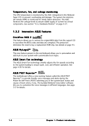
...page 4-5. See page 4-38 for details. 1-4 Chapter 1: Product introduction See details on page 4-37. 1.3.2 Innovative ASUS features CrashFree BIOS 2 This feature allows you to restore the original BIOS data from the support CD in the motherboard allows you to customize the voice messages in the Winbond Super I/O) to... your system with customizable boot logos. ASUS MyLogo2™ This new feature present in case when the BIOS codes and data are corrupted. The bundled Winbond Voice Editor software lets you to personalize and ...
...page 4-5. See page 4-38 for details. 1-4 Chapter 1: Product introduction See details on page 4-37. 1.3.2 Innovative ASUS features CrashFree BIOS 2 This feature allows you to restore the original BIOS data from the support CD in the motherboard allows you to customize the voice messages in the Winbond Super I/O) to... your system with customizable boot logos. ASUS MyLogo2™ This new feature present in case when the BIOS codes and data are corrupted. The bundled Winbond Voice Editor software lets you to personalize and ...
User Guide
Page 34
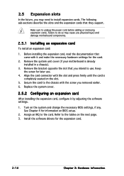
... it and make the necessary hardware settings for later use . Install the software drivers for information on the system and change the necessary BIOS settings, if any. The following sub-sections describe the slots and the expansion cards that came with the screw you intend to the ...chassis with it by adjusting the software settings. 1. Remove the system unit cover (if your motherboard is completely seated on the slot. 5. Turn on BIOS setup. 2. Align the card connector with the slot and press firmly until the card is already installed in a chassis). 3. See Chapter 4 for the...
... it and make the necessary hardware settings for later use . Install the software drivers for information on the system and change the necessary BIOS settings, if any. The following sub-sections describe the slots and the expansion cards that came with the screw you intend to the ...chassis with it by adjusting the software settings. 1. Remove the system unit cover (if your motherboard is completely seated on the slot. 5. Turn on BIOS setup. 2. Align the card connector with the slot and press firmly until the card is already installed in a chassis). 3. See Chapter 4 for the...
User Guide
Page 37
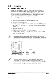
...from pins 1-2 (default) to overclocking. Turn OFF the computer and unplug the power cord. 2. Keep the cap on CLRTC jumper default position. ASUS K8N-DL 2-17 Clear RTC RAM (CLRTC1) This jumper allows you to clear the Real Time Clock (RTC) RAM in CMOS, which include system setup ...Re-install the battery. 5. Shut down the key during the boot process and enter BIOS setup to overclocking, use the C.P.R. (CPU Parameter Recall) feature. Removing the cap will cause system boot failure! ® K8N-DL K8N-DL Clear RTC RAM CLRTC1 12 23 Normal (Default) Clear CMOS You do not need...
...from pins 1-2 (default) to overclocking. Turn OFF the computer and unplug the power cord. 2. Keep the cap on CLRTC jumper default position. ASUS K8N-DL 2-17 Clear RTC RAM (CLRTC1) This jumper allows you to clear the Real Time Clock (RTC) RAM in CMOS, which include system setup ...Re-install the battery. 5. Shut down the key during the boot process and enter BIOS setup to overclocking, use the C.P.R. (CPU Parameter Recall) feature. Removing the cap will cause system boot failure! ® K8N-DL K8N-DL Clear RTC RAM CLRTC1 12 23 Normal (Default) Clear CMOS You do not need...

User Guide
Page 38
... Space Bar). KBPWR1 1 2 +5V (Default) 2 3 +5VSB ® K8N-DL K8N-DL Keyboard power setting 3 . 1394 controller setting (3-pin 1394_EN1) This jumper allows you to activate the 1394 feature. ® K8N-DL K8N-DL 1394 function setting 1394_EN 12 23 Enable (Default) Disable 2-18 Chapter 2: Hardware ...information Keyboard power (3-pin KBPWR1) This jumper allows you press a key on the +5VSB lead, and a corresponding setting in the BIOS. Set this jumper to...
... Space Bar). KBPWR1 1 2 +5V (Default) 2 3 +5VSB ® K8N-DL K8N-DL Keyboard power setting 3 . 1394 controller setting (3-pin 1394_EN1) This jumper allows you to activate the 1394 feature. ® K8N-DL K8N-DL 1394 function setting 1394_EN 12 23 Enable (Default) Disable 2-18 Chapter 2: Hardware ...information Keyboard power (3-pin KBPWR1) This jumper allows you press a key on the +5VSB lead, and a corresponding setting in the BIOS. Set this jumper to...
User Guide
Page 44
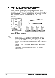
... a disk array through the onboard Silicon Image Sil3114 SATA RAID controller. ® K8N-DL SATA_RAID1 SATA_RAID2 SATA_RAID3 SATA_RAID4 K8N-DL SATA RAID connectors • Before creating a RAID configuration, make sure that you cannot enter the Silicon Image RAID utility and Serial ATA BIOS setup during POST. • The RAID 5 driver is not Windows Hardware Quality...
... a disk array through the onboard Silicon Image Sil3114 SATA RAID controller. ® K8N-DL SATA_RAID1 SATA_RAID2 SATA_RAID3 SATA_RAID4 K8N-DL SATA RAID connectors • Before creating a RAID configuration, make sure that you cannot enter the Silicon Image RAID utility and Serial ATA BIOS setup during POST. • The RAID 5 driver is not Windows Hardware Quality...
User Guide
Page 50
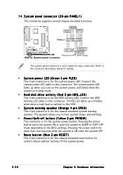
... IDE LED lights up when you to this connector. PWR GND Reset GND ® K8N-DL HD_LED RESET PWRSW * Requires an ATX power supply. The speaker allows you turn on the BIOS settings. System panel connector (20-pin PANEL1) This connector supports several chassis-mounted functions.... easy connection. Refer to this connector. 14. MLED PLED SPKO PLED+ PLEDMLED+ MLED+5V Ground Ground Speaker PANEL1 HD_LED+ HD_LED- K8N-DL System panel connector The system panel connector is for the chassis-mounted system warning speaker. Pressing the power button turns the system ON...
... IDE LED lights up when you to this connector. PWR GND Reset GND ® K8N-DL HD_LED RESET PWRSW * Requires an ATX power supply. The speaker allows you turn on the BIOS settings. System panel connector (20-pin PANEL1) This connector supports several chassis-mounted functions.... easy connection. Refer to this connector. 14. MLED PLED SPKO PLED+ PLEDMLED+ MLED+5V Ground Ground Speaker PANEL1 HD_LED+ HD_LED- K8N-DL System panel connector The system panel connector is for the chassis-mounted system warning speaker. Pressing the power button turns the system ON...

User Guide
Page 53
... connector at the back of the system chassis. 4. If your retailer for the first time 1. After making all switches are running, the BIOS beeps (see anything within 30 seconds from the time you press the ATX power button. Connect the power cord to enter the...system may light up . Turn on . System power 6. External SCSI devices (starting with a surge protector. 5. While the tests are off. 3. ASUS K8N-DL 3-1 If you do not see BIOS beep codes table below) or additional messages appear on test. For systems with "green" standards or if it has a "power standby" feature, the...
... connector at the back of the system chassis. 4. If your retailer for the first time 1. After making all switches are running, the BIOS beeps (see anything within 30 seconds from the time you press the ATX power button. Connect the power cord to enter the...system may light up . Turn on . System power 6. External SCSI devices (starting with a surge protector. 5. While the tests are off. 3. ASUS K8N-DL 3-1 If you do not see BIOS beep codes table below) or additional messages appear on test. For systems with "green" standards or if it has a "power standby" feature, the...

User Guide
Page 54
... then select T u r n O f f C o m p u t e r . 2. Pressing the power switch for more than four seconds puts the system to sleep mode or to soft-off mode regardless of the BIOS setting. Click the S t a r t button then click S h u t D o w n . . . 2. Make sure that the S h u t D o w n option button is ON, pressing the power switch for details. 3-2 Chapter 3: Powering up Click ...the T u r n O f f button to section "4.5 Power Menu" in Chapter 4 for less than four seconds lets the system enter the soft-off mode, depending on the BIOS setting. If you are using Windows® 2000: 1.
... then select T u r n O f f C o m p u t e r . 2. Pressing the power switch for more than four seconds puts the system to sleep mode or to soft-off mode regardless of the BIOS setting. Click the S t a r t button then click S h u t D o w n . . . 2. Make sure that the S h u t D o w n option button is ON, pressing the power switch for details. 3-2 Chapter 3: Powering up Click ...the T u r n O f f button to section "4.5 Power Menu" in Chapter 4 for less than four seconds lets the system enter the soft-off mode, depending on the BIOS setting. If you are using Windows® 2000: 1.
User Guide
Page 55
See the ASUS contact information on the inside front cover of this user guide. • Install supported DDR DIMMs into the PCI Express x16 slot. • Make sure that your graphics card is not defective. • Check your CPU overclocking settings in the BIOS setup and restore the default CPU ...to the purple PS/2 connector on the rear panel. • See section "2.7.1 Rear panel connectors" for assistance. You can record your package. ASUS K8N-DL 3-3 See section "2.3 Central Processing Unit (CPU)" for details. • Check the CPU if properly installed. • Call...
See the ASUS contact information on the inside front cover of this user guide. • Install supported DDR DIMMs into the PCI Express x16 slot. • Make sure that your graphics card is not defective. • Check your CPU overclocking settings in the BIOS setup and restore the default CPU ...to the purple PS/2 connector on the rear panel. • See section "2.7.1 Rear panel connectors" for assistance. You can record your package. ASUS K8N-DL 3-3 See section "2.3 Central Processing Unit (CPU)" for details. • Check the CPU if properly installed. • Call...

User Guide
Page 56
See the "ASUS contact information" on after you apply power to the system. • Make sure that your CPU fan supports the fan speed detection function. • Check ... system Action • Check if the CPU fan is working properly. • Check the CPU fan and make sure it is not defective. • Call ASUS technical support for details. 3-4 Chapter 3: Powering up See section 4.4.4 for assistance. POST Message CPU temperature too high CPU fan failed CPU voltage out of this...
See the "ASUS contact information" on after you apply power to the system. • Make sure that your CPU fan supports the fan speed detection function. • Check ... system Action • Check if the CPU fan is working properly. • Check the CPU fan and make sure it is not defective. • Call ASUS technical support for details. 3-4 Chapter 3: Powering up See section 4.4.4 for assistance. POST Message CPU temperature too high CPU fan failed CPU voltage out of this...

User Guide
Page 61
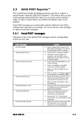
Detailed descriptions of the BIOS parameters are also provided. 4 BIOS setup This chapter tells how to change the system settings through the BIOS Setup menus.
Detailed descriptions of the BIOS parameters are also provided. 4 BIOS setup This chapter tells how to change the system settings through the BIOS Setup menus.

User Guide
Page 62
Chapter summary 4 4.1 Managing and updating your BIOS 4-1 4.2 BIOS setup program 4-11 4.3 Main menu 4-15 4.4 Advanced menu 4-20 4.5 Power menu 4-33 4.6 Boot menu 4-39 4.7 Exit menu 4-45 ASUS K8N-DL
Chapter summary 4 4.1 Managing and updating your BIOS 4-1 4.2 BIOS setup program 4-11 4.3 Main menu 4-15 4.4 Advanced menu 4-20 4.5 Power menu 4-33 4.6 Boot menu 4-39 4.7 Exit menu 4-45 ASUS K8N-DL
User Guide
Page 63
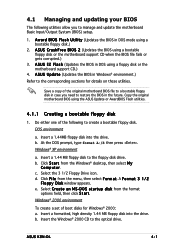
... a 1.44MB floppy disk into the drive. A F o r m a t 3 1 / 2 F l o p p y D i s k window appears. D O S s t a r t u p d i s k from the menu, then select F o r m a t. b. Insert the Windows® 2000 CD to the floppy disk drive. ASUS K8N-DL 4-1 A S U S E Z F l a s h (Updates the BIOS in DOS mode using a floppy disk or the motherboard support CD.) 4. DOS environment a. b. At the DOS prompt, type format A:/S then press . Click F i l e from the...
... a 1.44MB floppy disk into the drive. A F o r m a t 3 1 / 2 F l o p p y D i s k window appears. D O S s t a r t u p d i s k from the menu, then select F o r m a t. b. Insert the Windows® 2000 CD to the floppy disk drive. ASUS K8N-DL 4-1 A S U S E Z F l a s h (Updates the BIOS in DOS mode using a floppy disk or the motherboard support CD.) 4. DOS environment a. b. At the DOS prompt, type format A:/S then press . Click F i l e from the...
User Guide
Page 64
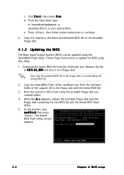
... NF-KC804-K8N-DL-00 DATE: 02/01/2005 Flash Type - Copy the original or the latest motherboard BIOS file to the floppy disk with the floppy disk containing the new BIOS file and the Award BIOS Flash Utility. 5. Boot the system in the floppy disk to update the BIOS using this ...utility. 1. The Award AwardBIOS Flash Utility for ASUS V1.01 (C) Phoenix Technologies Ltd. Click S t a r t, then select R...
... NF-KC804-K8N-DL-00 DATE: 02/01/2005 Flash Type - Copy the original or the latest motherboard BIOS file to the floppy disk with the floppy disk containing the new BIOS file and the Award BIOS Flash Utility. 5. Boot the system in the floppy disk to update the BIOS using this ...utility. 1. The Award AwardBIOS Flash Utility for ASUS V1.01 (C) Phoenix Technologies Ltd. Click S t a r t, then select R...

User Guide
Page 65
... to Continue restart the system. 111122223333 Write OK 111122223333 No Update 111122223333 Write Fail F1 Reset ASUS K8N-DL 4-3 SST 49LF004A/B /3.3V flashed the BIOS file. All Rights Reserved P r o g r a m field, then press . All Rights Reserved For NF-KC804-K8N-DL-00 DATE: 02/01/2005 Flash Type - All Rights Reserved message indicating that you to Program...
... to Continue restart the system. 111122223333 Write OK 111122223333 No Update 111122223333 Write Fail F1 Reset ASUS K8N-DL 4-3 SST 49LF004A/B /3.3V flashed the BIOS file. All Rights Reserved P r o g r a m field, then press . All Rights Reserved For NF-KC804-K8N-DL-00 DATE: 02/01/2005 Flash Type - All Rights Reserved message indicating that you to Program...

User Guide
Page 66
... Flash Utility: 1. 4.1.3 Saving the current BIOS file You can load the current BIOS file when the BIOS file gets corrupted during the flashing process. You can use the AwardBIOS Flash Utility to For NF-KC804-K8N-DL-00 DATE: 02/01/2005 Flash Type - All Rights Reserved 2. Type a filename for ASUS V1.01 (C) Phoenix Technologies Ltd...
... Flash Utility: 1. 4.1.3 Saving the current BIOS file You can load the current BIOS file when the BIOS file gets corrupted during the flashing process. You can use the AwardBIOS Flash Utility to For NF-KC804-K8N-DL-00 DATE: 02/01/2005 Flash Type - All Rights Reserved 2. Type a filename for ASUS V1.01 (C) Phoenix Technologies Ltd...


