

User Guide
Page 1
Motherboard H110I-PLUS D3
Motherboard H110I-PLUS D3
User Guide
Page 3
Contents Safety information iv About this guide iv Package contents vi H110I-PLUS D3 specifications summary vi Chapter 1: Product introduction 1.1 Before you proceed 1-1 1.2 Motherboard overview 1-2 1.3 Central Processing Unit (CPU 1-4 1.4 System memory 1-7 1.5 Expansion slots 1-10 1.6 Headers 1-11 1.7 Connectors 1-12 1.8 Software support 1-20 Chapter 2: BIOS information 2.1 Managing and ...2.5 Ai Tweaker menu 2-16 2.6 Advanced menu 2-22 2.7 Monitor menu 2-29 2.8 Boot menu 2-32 2.9 Tool menu 2-37 2.10 Exit menu 2-38 Appendices Notices...A-1 ASUS contact information A-4 iii
Contents Safety information iv About this guide iv Package contents vi H110I-PLUS D3 specifications summary vi Chapter 1: Product introduction 1.1 Before you proceed 1-1 1.2 Motherboard overview 1-2 1.3 Central Processing Unit (CPU 1-4 1.4 System memory 1-7 1.5 Expansion slots 1-10 1.6 Headers 1-11 1.7 Connectors 1-12 1.8 Software support 1-20 Chapter 2: BIOS information 2.1 Managing and ...2.5 Ai Tweaker menu 2-16 2.6 Advanced menu 2-22 2.7 Monitor menu 2-29 2.8 Boot menu 2-32 2.9 Tool menu 2-37 2.10 Exit menu 2-38 Appendices Notices...A-1 ASUS contact information A-4 iii

User Guide
Page 4
...user guide contains the information you detect any area where it may be exposed to moisture. • Place the product on the motherboard. • Chapter 2: BIOS information This chapter discusses changing system settings through the BIOS Setup menus. These devices could interrupt the grounding... system, ensure that the power cables for the BIOS parameters are also provided. If possible, disconnect all power cables from the motherboard, ensure that came with the product, contact a qualified service technician or your retailer. iv If you encounter technical problems with the...
...user guide contains the information you detect any area where it may be exposed to moisture. • Place the product on the motherboard. • Chapter 2: BIOS information This chapter discusses changing system settings through the BIOS Setup menus. These devices could interrupt the grounding... system, ensure that the power cables for the BIOS parameters are also provided. If possible, disconnect all power cables from the motherboard, ensure that came with the product, contact a qualified service technician or your retailer. iv If you encounter technical problems with the...
User Guide
Page 6
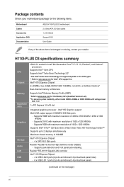
...shared memory of 4096 x 2160 @24Hz / 2560 x 1600 @60Hz - Supports jack-detection and front panel jack-retasking. H110I-PLUS D3 specifications summary CPU Chipset Memory Expansion slots Graphics Storage Audio LAN USB LGA1151 socket for Intel® 6th Generation Core™... panel) (continued on the CPU types. ** Refer to www.asus.com for Intel® CPU support list. Package contents Check your motherboard package for the following items. Motherboard Cables Accessories Application DVD Documentation ASUS H110I-PLUS D3 motherboard 2 x Serial ATA 6.0 Gb/s cables 1 x I/O Shield ...
...shared memory of 4096 x 2160 @24Hz / 2560 x 1600 @60Hz - Supports jack-detection and front panel jack-retasking. H110I-PLUS D3 specifications summary CPU Chipset Memory Expansion slots Graphics Storage Audio LAN USB LGA1151 socket for Intel® 6th Generation Core™... panel) (continued on the CPU types. ** Refer to www.asus.com for Intel® CPU support list. Package contents Check your motherboard package for the following items. Motherboard Cables Accessories Application DVD Documentation ASUS H110I-PLUS D3 motherboard 2 x Serial ATA 6.0 Gb/s cables 1 x I/O Shield ...

User Guide
Page 9
... wrist strap or touch a safely grounded object or a metal object, such as the power supply case, to avoid damaging them due to the motherboard, peripherals, or components. ASUS H110I-PLUS D3 1-1 Failure to do so may cause severe damage to static electricity. • Before you install or remove any component, ensure that the ATX power...
... wrist strap or touch a safely grounded object or a metal object, such as the power supply case, to avoid damaging them due to the motherboard, peripherals, or components. ASUS H110I-PLUS D3 1-1 Failure to do so may cause severe damage to static electricity. • Before you install or remove any component, ensure that the ATX power...

User Guide
Page 10
... holes Place four screws into the holes indicated by circles to secure the motherboard to the chassis. Unplug the power cord before installing or removing the motherboard. Do not overtighten the screws! Failure to the rear part of the chassis H110I-PLUS D3 1-2 Chapter 1: Product introduction Place this side towards the rear of the chassis...
... holes Place four screws into the holes indicated by circles to secure the motherboard to the chassis. Unplug the power cord before installing or removing the motherboard. Do not overtighten the screws! Failure to the rear part of the chassis H110I-PLUS D3 1-2 Chapter 1: Product introduction Place this side towards the rear of the chassis...
User Guide
Page 11
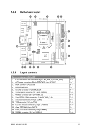
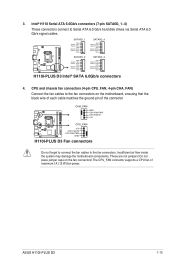
... 2.0 connector (10-1 pin USB910) F_PANEL EATX_PWR 17.0cm(6.7in) 2 6 7 8 Page 1-15 1-17 1-4 1-7 1-17 1-18 1-16 1-15 1-14 1-18 1-19 1-11 1-14 1-16 ASUS H110I-PLUS D3 1-3 Serial ATA 6.0 Gb/s connectors (7-pin SATA6G_1~4) 9. 1.2.3 Motherboard layout 1 2 3 17.0cm(6.7in) KBMS_USB78 ATX12V BATTERY CHA_FAN HDMI ASM 1442K LGA1151 45 SPEAKER DDR3_DIMM_B1 (64bit, 240-pin module) DDR3_DIMM_A1 (64bit, 240...
... 2.0 connector (10-1 pin USB910) F_PANEL EATX_PWR 17.0cm(6.7in) 2 6 7 8 Page 1-15 1-17 1-4 1-7 1-17 1-18 1-16 1-15 1-14 1-18 1-19 1-11 1-14 1-16 ASUS H110I-PLUS D3 1-3 Serial ATA 6.0 Gb/s connectors (7-pin SATA6G_1~4) 9. 1.2.3 Motherboard layout 1 2 3 17.0cm(6.7in) KBMS_USB78 ATX12V BATTERY CHA_FAN HDMI ASM 1442K LGA1151 45 SPEAKER DDR3_DIMM_B1 (64bit, 240-pin module) DDR3_DIMM_A1 (64bit, 240...
User Guide
Page 12
...ASUS will process Return Merchandise Authorization (RMA) requests only if the motherboard comes with a surface mount LGA1151 socket designed for 6th Generation Intel® Core™ i7 / i5 / i3, Pentium®, and Celeron® processors. DO NOT install a CPU designed for the LGA1151 socket only. H110I-PLUS D3... CPU designed for LGA1150, LGA1155 and LGA1156 sockets on the socket and the socket contacts are not bent. H110I-PLUS D3 1.3 Central Processing Unit (CPU) This motherboard comes with the cap on the LGA1151 socket. • The product warranty does not cover damage to the...
...ASUS will process Return Merchandise Authorization (RMA) requests only if the motherboard comes with a surface mount LGA1151 socket designed for 6th Generation Intel® Core™ i7 / i5 / i3, Pentium®, and Celeron® processors. DO NOT install a CPU designed for the LGA1151 socket only. H110I-PLUS D3... CPU designed for LGA1150, LGA1155 and LGA1156 sockets on the socket and the socket contacts are not bent. H110I-PLUS D3 1.3 Central Processing Unit (CPU) This motherboard comes with the cap on the LGA1151 socket. • The product warranty does not cover damage to the...

User Guide
Page 15
To uninstall the CPU heatsink and fan assembly 1 2 A B B A 1.4 System memory 1.4.1 Overview This motherboard comes with two Double Data Rate 3 (DDR3) Dual Inline Memory Module (DIMM) sockets. The figure illustrates the location of the DDR3 DIMM sockets: H110I-PLUS D3 DIMM_A1 DIMM_B1 Channel Channel A Channel B Sockets DIMM_A1 DIMM_B1 H110I-PLUS D3 240-pin DDR3 DIMM sockets ASUS H110I-PLUS D3 1-7
To uninstall the CPU heatsink and fan assembly 1 2 A B B A 1.4 System memory 1.4.1 Overview This motherboard comes with two Double Data Rate 3 (DDR3) Dual Inline Memory Module (DIMM) sockets. The figure illustrates the location of the DDR3 DIMM sockets: H110I-PLUS D3 DIMM_A1 DIMM_B1 Channel Channel A Channel B Sockets DIMM_A1 DIMM_B1 H110I-PLUS D3 240-pin DDR3 DIMM sockets ASUS H110I-PLUS D3 1-7

User Guide
Page 16
... varying memory sizes in Channel A and Channel B. For an optimum compatibility, we recommend that you install 4GB or more memory on the motherboard, the actual usable memory for manual memory frequency adjustment. • Always install the DIMMs with the vendor to install 4GB or more details...population below. Check with the same CAS Latency. Use a maximum of the following: - Any excess memory from a memory module. Visit the ASUS website at a higher frequency, refer to section 2.5 Ai Tweaker menu for the OS can refer to the memory address limitation on 32-bit Windows...
... varying memory sizes in Channel A and Channel B. For an optimum compatibility, we recommend that you install 4GB or more memory on the motherboard, the actual usable memory for manual memory frequency adjustment. • Always install the DIMMs with the vendor to install 4GB or more details...population below. Check with the same CAS Latency. Use a maximum of the following: - Any excess memory from a memory module. Visit the ASUS website at a higher frequency, refer to section 2.5 Ai Tweaker menu for the OS can refer to the memory address limitation on 32-bit Windows...
User Guide
Page 18
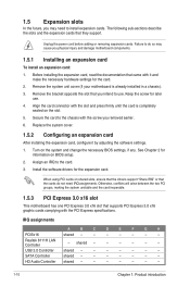
... 4. Otherwise, conflicts will arise between the two PCI groups, making the system unstable and the card inoperable. 1.5.3 PCI Express 3.0 x16 slot This motherboard has one PCI Express 3.0 x16 slot that the cards do so may need IRQ assignments. shared - - - - - - The following sub&#...slots and the expansion cards that you intend to the chassis with it by adjusting the software settings. 1. Remove the system unit cover (if your motherboard is completely seated on BIOS setup. 2. USB 3.0 Controller shared - - - - - - - Remove the bracket opposite the slot that they...
... 4. Otherwise, conflicts will arise between the two PCI groups, making the system unstable and the card inoperable. 1.5.3 PCI Express 3.0 x16 slot This motherboard has one PCI Express 3.0 x16 slot that the cards do so may need IRQ assignments. shared - - - - - - The following sub&#...slots and the expansion cards that you intend to the chassis with it by adjusting the software settings. 1. Remove the system unit cover (if your motherboard is completely seated on BIOS setup. 2. USB 3.0 Controller shared - - - - - - - Remove the bracket opposite the slot that they...

User Guide
Page 22
...connector, set the Front Panel Type item in the BIOS setup to this connector. Connect the serial port module cable to [HD Audio]. AAFP H110I-PLUS D3 SENSE2_RETUR SENSE1_RETUR NC AGND PORT2 L NC SENSE_SEND PORT2 R NC PORT1 R NC PORT1 L AGND PIN 1 Line out_L NC Line out_R MICPWR MIC2 ... of the front panel audio I /O module that you connect a high-definition front panel audio module to this connector to avail of the motherboard's high-definition audio capability. • If you want to connect a high-definition front panel audio module to this connector is for a ...
...connector, set the Front Panel Type item in the BIOS setup to this connector. Connect the serial port module cable to [HD Audio]. AAFP H110I-PLUS D3 SENSE2_RETUR SENSE1_RETUR NC AGND PORT2 L NC SENSE_SEND PORT2 R NC PORT1 R NC PORT1 L AGND PIN 1 Line out_L NC Line out_R MICPWR MIC2 ... of the front panel audio I /O module that you connect a high-definition front panel audio module to this connector to avail of the motherboard's high-definition audio capability. • If you want to connect a high-definition front panel audio module to this connector is for a ...
User Guide
Page 23
ASUS H110I-PLUS D3 1-15 Insufficient air flow inside the system may damage the motherboard components. These are not jumpers! Do not place jumper caps on the motherboard, ensuring that the black wire of each cable matches the ground pin of maximum 1A (12 W) fan power. SATA6G_1 GND RSATA_TXP1 RSATA_TXN1 GND RSATA_RXN1 RSATA_RXP1 ...
ASUS H110I-PLUS D3 1-15 Insufficient air flow inside the system may damage the motherboard components. These are not jumpers! Do not place jumper caps on the motherboard, ensuring that the black wire of each cable matches the ground pin of maximum 1A (12 W) fan power. SATA6G_1 GND RSATA_TXP1 RSATA_TXN1 GND RSATA_RXN1 RSATA_RXP1 ...

User Guide
Page 24
... GND USB_P10+ USB_P10USB+5V PIN 1 H110I-PLUS D3 USB2.0 connector Never connect a 1394 cable to connect a USB 3.0 module for USB 2.0 ports. The USB 2.0 module is purchased separately. 6. USB 2.0 connector (10-1 pin USB910) This connector is for additional USB 3.0 front or rear panel ports. 5. Doing so will damage the motherboard! USB 3.0 connector (20-1 pin USB3_12...
... GND USB_P10+ USB_P10USB+5V PIN 1 H110I-PLUS D3 USB2.0 connector Never connect a 1394 cable to connect a USB 3.0 module for USB 2.0 ports. The USB 2.0 module is purchased separately. 6. USB 2.0 connector (10-1 pin USB910) This connector is for additional USB 3.0 front or rear panel ports. 5. Doing so will damage the motherboard! USB 3.0 connector (20-1 pin USB3_12...

User Guide
Page 28
...time without notice. The contents of the Support DVD are subject to change at www.asus.com for detailed information. 1.8.2 Support DVD information The Support DVD that comes with the motherboard package contains the drivers, software applications, and utilities that you can install to run ...Support DVD Place the Support DVD into the optical drive. The following screen is NOT enabled in your ASUS motherboard. Double-click the Setup.exe to avail all motherboard features. Motherboard settings and hardware options vary. Click an icon to display a tab Click to install Tick an item...
...time without notice. The contents of the Support DVD are subject to change at www.asus.com for detailed information. 1.8.2 Support DVD information The Support DVD that comes with the motherboard package contains the drivers, software applications, and utilities that you can install to run ...Support DVD Place the Support DVD into the optical drive. The following screen is NOT enabled in your ASUS motherboard. Double-click the Setup.exe to avail all motherboard features. Motherboard settings and hardware options vary. Click an icon to display a tab Click to install Tick an item...
User Guide
Page 29
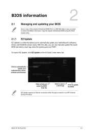
... file to a USB flash disk in case you need to restore the BIOS in the future. Copy the original motherboard BIOS using the ASUS Update utility. 2.1.1 EZ Update EZ Update is a utility that allows you can also manually update the saved BIOS and select a boot... Managing and updating your motherboard's softwares, drivers and the BIOS version easily. With this utlity, you to update the BIOS EZ Update requires an Internet connection either through a network or an ISP (Internet Service Provider). To launch EZ Update, click EZ Update on the AI Suite 3 main menu bar. ASUS H110I-PLUS D3 2-1
... file to a USB flash disk in case you need to restore the BIOS in the future. Copy the original motherboard BIOS using the ASUS Update utility. 2.1.1 EZ Update EZ Update is a utility that allows you can also manually update the saved BIOS and select a boot... Managing and updating your motherboard's softwares, drivers and the BIOS version easily. With this utlity, you to update the BIOS EZ Update requires an Internet connection either through a network or an ISP (Internet Service Provider). To launch EZ Update, click EZ Update on the AI Suite 3 main menu bar. ASUS H110I-PLUS D3 2-1
User Guide
Page 31
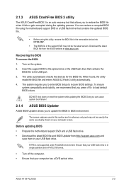
... file. Before updating BIOS • Prepare the motherboard support DVD and a USB flash drive. • Download the latest BIOS file and BIOS Updater from the ASUS website at www.asus.com. Recovering the BIOS To recover the BIOS: 1. Turn on your computer has a DVD optical drive. ASUS H110I-PLUS D3 2-3 To ensure system compatibility and stability, we...
... file. Before updating BIOS • Prepare the motherboard support DVD and a USB flash drive. • Download the latest BIOS file and BIOS Updater from the ASUS website at www.asus.com. Recovering the BIOS To recover the BIOS: 1. Turn on your computer has a DVD optical drive. ASUS H110I-PLUS D3 2-3 To ensure system compatibility and stability, we...

User Guide
Page 34
...BIOS file for information on your screen. • Visit the ASUS website at startup: Press or during the Power-On Self Test (POST). Press the reset button on . BIOS menu screen The BIOS setup program can cause damage to your motherboard if you always shut down the system properly from a running..., or the ++ keys to force reset from the operating system. • The BIOS setup screens shown in using the first two options. Do this motherboard. • Ensure that a mouse is connected to your data or system. 2.2 BIOS setup program Use the BIOS Setup program to update the BIOS or...
...BIOS file for information on your screen. • Visit the ASUS website at startup: Press or during the Power-On Self Test (POST). Press the reset button on . BIOS menu screen The BIOS setup program can cause damage to your motherboard if you always shut down the system properly from a running..., or the ++ keys to force reset from the operating system. • The BIOS setup screens shown in using the first two options. Do this motherboard. • Ensure that a mouse is connected to your data or system. 2.2 BIOS setup program Use the BIOS Setup program to update the BIOS or...

User Guide
Page 35
...setup program Displays the CPU Fan's speed. Click to select the display language, system performance mode, fan profile and boot device priority. ASUS H110I-PLUS D3 2-7 Refer to manually tune the fans Loads optimized default settings Shows the bootable devices Saves the changes and resets the system Displays the.... The default screen for details. To access the Advanced Mode, click Advanced Mode(F7) or press . Displays the CPU/motherboard temperature, CPU voltage output, CPU/chassis fan speed, and SATA information Displays the system properties of the selected mode.
...setup program Displays the CPU Fan's speed. Click to select the display language, system performance mode, fan profile and boot device priority. ASUS H110I-PLUS D3 2-7 Refer to manually tune the fans Loads optimized default settings Shows the bootable devices Saves the changes and resets the system Displays the.... The default screen for details. To access the Advanced Mode, click Advanced Mode(F7) or press . Displays the CPU/motherboard temperature, CPU voltage output, CPU/chassis fan speed, and SATA information Displays the system properties of the selected mode.

User Guide
Page 36
Refer to EZ Mode Popup window Last modified settings Search on FAQs Displays the CPU/motherboard temperature, CPU and memory voltage output 2-8 Chapter 2: Getting started To access the EZ Mode, click EzMode(F7) or press . The figure below shows an example ...
Refer to EZ Mode Popup window Last modified settings Search on FAQs Displays the CPU/motherboard temperature, CPU and memory voltage output 2-8 Chapter 2: Getting started To access the EZ Mode, click EzMode(F7) or press . The figure below shows an example ...


