
User Guide
Page 2
... location where you give us a notification to obtain the corresponding source code and your request please provide the name, model number and version, as stated in this email address). ASUSTeK is defaced or missing. No part of the product for free by ASUS; SPECIFICATIONS AND INFORMATION CONTAINED IN THIS MANUAL ARE FURNISHED FOR INFORMATIONAL USE ONLY, AND ARE SUBJECT TO CHANGE...
... location where you give us a notification to obtain the corresponding source code and your request please provide the name, model number and version, as stated in this email address). ASUSTeK is defaced or missing. No part of the product for free by ASUS; SPECIFICATIONS AND INFORMATION CONTAINED IN THIS MANUAL ARE FURNISHED FOR INFORMATIONAL USE ONLY, AND ARE SUBJECT TO CHANGE...
User Guide
Page 6
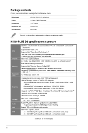
... Application DVD Documentation ASUS H110I-PLUS D3 motherboard 2 x Serial ATA 6.0 Gb/s cables 1 x I/O Shield Support DVD User Guide If any of 1920 x 1200 @60Hz Supports Intel® InTru™ 3D/ Quick Sync Video/ Clear Video HD Technology/ Insider™ Supports up to www.asus.com for the Memory QVL (Qualified Vendors List). **To prevent system instability, either install DDR3L DIMMs or DDR3 DIMMs with voltage lower than 1.5V. 1 x PCI Express 3.0 x16 slot Integrated graphics processor - Intel® H110 Express Chipset 2 x DIMMs, max...
... Application DVD Documentation ASUS H110I-PLUS D3 motherboard 2 x Serial ATA 6.0 Gb/s cables 1 x I/O Shield Support DVD User Guide If any of 1920 x 1200 @60Hz Supports Intel® InTru™ 3D/ Quick Sync Video/ Clear Video HD Technology/ Insider™ Supports up to www.asus.com for the Memory QVL (Qualified Vendors List). **To prevent system instability, either install DDR3L DIMMs or DDR3 DIMMs with voltage lower than 1.5V. 1 x PCI Express 3.0 x16 slot Integrated graphics processor - Intel® H110 Express Chipset 2 x DIMMs, max...

User Guide
Page 8
... USB 2.0/1.1 ports 4 x SATA 6.0Gb/s connectors 1 x CPU Fan connector 1 x Chassis Fan connector 1 x Front panel audio connector (AAFP) 1 x COM connector 1 x TPM connector (14-1 pin) 1 x 24-pin EATX Power connector 1 x 4-pin ATX 12V Power connector 1 x Clear CMOS header (2-pin) 1 x Speaker connector 1 x System panel connector 1 x Chassis intrusion connector 128Mb Flash ROM, UEFI AMI BIOS, PnP, DMI3.0, WfM2.0, SM BIOS 3.0, ACPI 5.0, Multi-language BIOS, ASUS EZ Flash 3, CrashFree BIOS 3 Drivers ASUS utilities EZ Update Anti-virus software (OEM version) Windows® 10* Windows® 8.1* Windows...
... USB 2.0/1.1 ports 4 x SATA 6.0Gb/s connectors 1 x CPU Fan connector 1 x Chassis Fan connector 1 x Front panel audio connector (AAFP) 1 x COM connector 1 x TPM connector (14-1 pin) 1 x 24-pin EATX Power connector 1 x 4-pin ATX 12V Power connector 1 x Clear CMOS header (2-pin) 1 x Speaker connector 1 x System panel connector 1 x Chassis intrusion connector 128Mb Flash ROM, UEFI AMI BIOS, PnP, DMI3.0, WfM2.0, SM BIOS 3.0, ACPI 5.0, Multi-language BIOS, ASUS EZ Flash 3, CrashFree BIOS 3 Drivers ASUS utilities EZ Update Anti-virus software (OEM version) Windows® 10* Windows® 8.1* Windows...
User Guide
Page 11
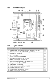
... (4-1 pin CHASSIS) 12. Serial port connector (10-1 pin COM1) 10. Clear RTC RAM (2-pin CLRTC) 13. USB 3.0 connector (20-1 pin USB3_12) 8. TPM connector (14-1 pin TPM) 11. Intel® LGA1151 CPU socket 4. DDR3 DIMM slots 5. USB 2.0 connector (10-1 pin USB910) F_PANEL EATX_PWR 17.0cm(6.7in) 2 6 7 8 Page 1-15 1-17 1-4 1-7 1-17 1-18 1-16 1-15 1-14 1-18 1-19 1-11 1-14 1-16 ASUS H110I-PLUS D3 1-3 Speaker connector (4-pin SPEAKER) 6. Front panel audio connector (10-1 pin AAFP) 14. CPU and chassis fan connectors (4-pin CPU_FAN, 4-pin CHA_FAN) 2. 1.2.3 Motherboard layout...
... (4-1 pin CHASSIS) 12. Serial port connector (10-1 pin COM1) 10. Clear RTC RAM (2-pin CLRTC) 13. USB 3.0 connector (20-1 pin USB3_12) 8. TPM connector (14-1 pin TPM) 11. Intel® LGA1151 CPU socket 4. DDR3 DIMM slots 5. USB 2.0 connector (10-1 pin USB910) F_PANEL EATX_PWR 17.0cm(6.7in) 2 6 7 8 Page 1-15 1-17 1-4 1-7 1-17 1-18 1-16 1-15 1-14 1-18 1-19 1-11 1-14 1-16 ASUS H110I-PLUS D3 1-3 Speaker connector (4-pin SPEAKER) 6. Front panel audio connector (10-1 pin AAFP) 14. CPU and chassis fan connectors (4-pin CPU_FAN, 4-pin CHA_FAN) 2. 1.2.3 Motherboard layout...

User Guide
Page 16
...-bit Windows® OS, when you do any of accessing information from a memory module. Under the default state, some memory modules for single-channel operation. • Due to the memory address limitation on its Serial Presence Detect (SPD), which is then mapped for overclocking may operate at a higher frequency, refer to get the correct memory modules. Visit the ASUS website at http://support.microsoft. Use...
...-bit Windows® OS, when you do any of accessing information from a memory module. Under the default state, some memory modules for single-channel operation. • Due to the memory address limitation on its Serial Presence Detect (SPD), which is then mapped for overclocking may operate at a higher frequency, refer to get the correct memory modules. Visit the ASUS website at http://support.microsoft. Use...
User Guide
Page 18
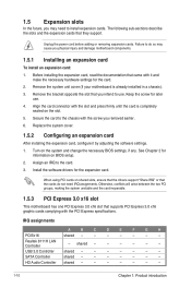
... slots, ensure that the drivers support "Share IRQ" or that supports PCI Express 3.0 x16 graphic cards complying with it by adjusting the software settings. 1. IRQ assignments A B C D E F G H PCIEx16 shared - - - - - - - USB 3.0 Controller shared - - - - - - - Assign an IRQ to the card. 3. SATA Controller shared - - - - - - - Remove the system unit cover (if your motherboard is completely seated on the system and change the necessary BIOS settings, if any. See Chapter 2 for later use . Secure the card to the chassis...
... slots, ensure that the drivers support "Share IRQ" or that supports PCI Express 3.0 x16 graphic cards complying with it by adjusting the software settings. 1. IRQ assignments A B C D E F G H PCIEx16 shared - - - - - - - USB 3.0 Controller shared - - - - - - - Assign an IRQ to the card. 3. SATA Controller shared - - - - - - - Remove the system unit cover (if your motherboard is completely seated on the system and change the necessary BIOS settings, if any. See Chapter 2 for later use . Secure the card to the chassis...
User Guide
Page 19
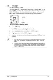
...- H110I-PLUS D3 +3V_BAT GND 1.6 Headers Clear RTC RAM (2-pin CLRTC) This header allows you to clear the Real Time Clock (RTC) RAM in CMOS, which include system setup information such as a screwdriver to short the two pins. 3. Use a metal object such as system passwords. Hold down and reboot the system, then the BIOS automatically resets parameter settings to default values. After clearing the CMOS, reinstall the battery. • You do not help, remove the onboard battery...
...- H110I-PLUS D3 +3V_BAT GND 1.6 Headers Clear RTC RAM (2-pin CLRTC) This header allows you to clear the Real Time Clock (RTC) RAM in CMOS, which include system setup information such as a screwdriver to short the two pins. 3. Use a metal object such as system passwords. Hold down and reboot the system, then the BIOS automatically resets parameter settings to default values. After clearing the CMOS, reinstall the battery. • You do not help, remove the onboard battery...
User Guide
Page 21
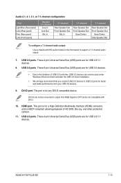
... your USB 3.0 devices. 9. Rear Speaker Out Front Speaker Out Bass/Center Side Speaker Out To configure a 7.1-channel audio output: Use a chassis with DVI-I. 10. This port is not compatible with HD audio module in the front panel to the limitation of HD DVD, Blu-ray, and other protected content. 11. USB 2.0 ports. ASUS H110I-PLUS D3 1-13 These 9-pin Universal Serial Bus (USB) ports are for USB 2.0/1.1 devices. 8. HDMI port. USB 2.0 ports. These 4-pin Universal Serial Bus (USB) ports are for USB 3.0 devices. • Due to support a 7.1-channel audio output. 7. USB...
... your USB 3.0 devices. 9. Rear Speaker Out Front Speaker Out Bass/Center Side Speaker Out To configure a 7.1-channel audio output: Use a chassis with DVI-I. 10. This port is not compatible with HD audio module in the front panel to the limitation of HD DVD, Blu-ray, and other protected content. 11. USB 2.0 ports. ASUS H110I-PLUS D3 1-13 These 9-pin Universal Serial Bus (USB) ports are for USB 2.0/1.1 devices. 8. HDMI port. USB 2.0 ports. These 4-pin Universal Serial Bus (USB) ports are for USB 3.0 devices. • Due to support a 7.1-channel audio output. 7. USB...
User Guide
Page 23
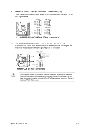
... GND H110I-PLUS D3 Intel® SATA 6.0Gb/s connectors 4. CPU and chassis fan connectors (4-pin CPU_FAN, 4-pin CHA_FAN) Connect the fan cables to the fan connectors on the fan connectors! Insufficient air flow inside the system may damage the motherboard components. These are not jumpers! Do not place jumper caps on the motherboard, ensuring that the black wire of each cable matches the ground pin of maximum 1A (12 W) fan power. ASUS H110I-PLUS D3 1-15 3. The CPU_FAN connector supports a CPU fan of the connector CHA_FAN...
... GND H110I-PLUS D3 Intel® SATA 6.0Gb/s connectors 4. CPU and chassis fan connectors (4-pin CPU_FAN, 4-pin CHA_FAN) Connect the fan cables to the fan connectors on the fan connectors! Insufficient air flow inside the system may damage the motherboard components. These are not jumpers! Do not place jumper caps on the motherboard, ensuring that the black wire of each cable matches the ground pin of maximum 1A (12 W) fan power. ASUS H110I-PLUS D3 1-15 3. The CPU_FAN connector supports a CPU fan of the connector CHA_FAN...

User Guide
Page 28
... Windows® 10 (64-bit) Operating Systems (OS). Motherboard settings and hardware options vary. Click the Driver, Utilities, Manual, or Special tabs to maximize the features of your computer, browse the contents of the Support DVD are subject to locate the file Setup.exe in your ASUS motherboard. Always install the latest OS version and corresponding updates to display their respective menus. The contents of the Support DVD to change at www.asus...
... Windows® 10 (64-bit) Operating Systems (OS). Motherboard settings and hardware options vary. Click the Driver, Utilities, Manual, or Special tabs to maximize the features of your computer, browse the contents of the Support DVD are subject to locate the file Setup.exe in your ASUS motherboard. Always install the latest OS version and corresponding updates to display their respective menus. The contents of the Support DVD to change at www.asus...
User Guide
Page 29
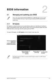
... the original motherboard BIOS file to a USB flash disk in the future. ASUS H110I-PLUS D3 2-1 With this utlity, you need to update the BIOS EZ Update requires an Internet connection either through a network or an ISP (Internet Service Provider). Copy the original motherboard BIOS using the ASUS Update utility. 2.1.1 EZ Update EZ Update is a utility that allows you to automatically update your motherboard's driver, software and firmware Click to find and select the BIOS from file Click to select a boot logo Click...
... the original motherboard BIOS file to a USB flash disk in the future. ASUS H110I-PLUS D3 2-1 With this utlity, you need to update the BIOS EZ Update requires an Internet connection either through a network or an ISP (Internet Service Provider). Copy the original motherboard BIOS using the ASUS Update utility. 2.1.1 EZ Update EZ Update is a utility that allows you to automatically update your motherboard's driver, software and firmware Click to find and select the BIOS from file Click to select a boot logo Click...
User Guide
Page 31
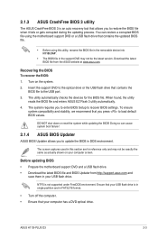
... stability, we recommend that contains the BIOS file to load default BIOS values. The screen captures used in the support DVD may not be the latest version. DO NOT shut down or reset the system while updating the BIOS! You can cause system boot failure! 2.1.4 ASUS BIOS Updater ASUS BIOS Updater allows you to enter BIOS Setup to update the BIOS in DOS environment. Turn on your USB flash drive. Download the latest BIOS file from http://support.asus.com and save them in FAT32...
... stability, we recommend that contains the BIOS file to load default BIOS values. The screen captures used in the support DVD may not be the latest version. DO NOT shut down or reset the system while updating the BIOS! You can cause system boot failure! 2.1.4 ASUS BIOS Updater ASUS BIOS Updater allows you to enter BIOS Setup to update the BIOS in DOS environment. Turn on your USB flash drive. Download the latest BIOS file from http://support.asus.com and save them in FAT32...

User Guide
Page 32
... BIOS Updater screen, press to switch from Drive C (optical drive) to Drives panel then select D:. 2-4 Chapter 2: Getting started When the select boot device screen appears, insert the Support DVD into the optical drive then select the optical drive as the boot device. Welcome to enter FreeDOS prompt. Press ENTER to the USB port. 2. Booting the system in DOS environment To boot the system in DOS: 1. Insert the USB flash drive with the latest BIOS file and BIOS Updater to boot from the DVD...
... BIOS Updater screen, press to switch from Drive C (optical drive) to Drives panel then select D:. 2-4 Chapter 2: Getting started When the select boot device screen appears, insert the Support DVD into the optical drive then select the optical drive as the boot device. Welcome to enter FreeDOS prompt. Press ENTER to the USB port. 2. Booting the system in DOS environment To boot the system in DOS: 1. Insert the USB flash drive with the latest BIOS file and BIOS Updater to boot from the DVD...

User Guide
Page 41
... 2. from the BIOS screen to My Favorites To add BIOS items: 1. 2.3 My Favorites MyFavorites is your personal space where you want to save and access your keyboard or click Setup Tree Map screen. On the Setup Tree Map screen, select the BIOS items that you can personalize this screen by default. You can easily save in MyFavorites screen. Main menu panel Submenu panel Selected shortcut items ASUS H110I-PLUS D3 2-13
... 2. from the BIOS screen to My Favorites To add BIOS items: 1. 2.3 My Favorites MyFavorites is your personal space where you want to save and access your keyboard or click Setup Tree Map screen. On the Setup Tree Map screen, select the BIOS items that you can personalize this screen by default. You can easily save in MyFavorites screen. Main menu panel Submenu panel Selected shortcut items ASUS H110I-PLUS D3 2-13
User Guide
Page 53
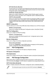
... power use when the system is installed to DVMT 5.0 used by the internal graphics device. DMI Max Link Speed [Auto] Allows you to configure the PCI Express configuration settings. Memory Remap [Enabled] Set this item to [Enabled] to support DRAM address remapping for 64-bit operating systems. Configuration options: [Enabled] [Disabled] 2.6.4 PCH Configuration This item allows you to configure the DMI speed. The SATA Port items show Empty if no SATA device is idle. PCIEx16_1 Link Speed [Auto] Allows you to configure the PCIe speed. SATA Controller(s) [Enabled] Enables or disables...
... power use when the system is installed to DVMT 5.0 used by the internal graphics device. DMI Max Link Speed [Auto] Allows you to configure the PCI Express configuration settings. Memory Remap [Enabled] Set this item to [Enabled] to support DRAM address remapping for 64-bit operating systems. Configuration options: [Enabled] [Disabled] 2.6.4 PCH Configuration This item allows you to configure the DMI speed. The SATA Port items show Empty if no SATA device is idle. PCIEx16_1 Link Speed [Auto] Allows you to configure the PCIe speed. SATA Controller(s) [Enabled] Enables or disables...

User Guide
Page 54
... to enable/disable SATA Hot Plug Support. If no USB device is designed for BIOS setup only and cannot be used for LPM (link power management) support with a better energy saving conditions. USB Single Port Control The subitems in the hard disks. Configuration options: [On] [Off] SATA6G_1~4(Gray) [Enabled] Allow you to enable/disable the SATA6G_3~6 port. Legacy USB Support [Enabled] [Enabled] Your system supports the USB devices in legacy operating systems. [Disabled] Your USB devices can be recognized in this menu allow you to set the USB Port Disable...
... to enable/disable SATA Hot Plug Support. If no USB device is designed for BIOS setup only and cannot be used for LPM (link power management) support with a better energy saving conditions. USB Single Port Control The subitems in the hard disks. Configuration options: [On] [Off] SATA6G_1~4(Gray) [Enabled] Allow you to enable/disable the SATA6G_3~6 port. Legacy USB Support [Enabled] [Enabled] Your system supports the USB devices in legacy operating systems. [Disabled] Your USB devices can be recognized in this menu allow you to set the USB Port Disable...

User Guide
Page 55
...] Enables the Realtek LAN controller. [Off] Disables the controller. State S5 is the soft-off mode or shutdown state where your computer has no memory state and is in this function. Configuration options: [Disabled] [Enabled] ASUS H110I-PLUS D3 2-27 Realtek PXE Option ROM [Off] This item appears only when you set the previous item to [On] and allows you set the front panel audio connector (AAFP) mode to legacy AC'97 or high-definition audio...
...] Enables the Realtek LAN controller. [Off] Disables the controller. State S5 is the soft-off mode or shutdown state where your computer has no memory state and is in this function. Configuration options: [Disabled] [Enabled] ASUS H110I-PLUS D3 2-27 Realtek PXE Option ROM [Off] This item appears only when you set the previous item to [On] and allows you set the front panel audio connector (AAFP) mode to legacy AC'97 or high-definition audio...

User Guide
Page 56
...requires an ATX power supply that provides at least 1A on -LAN function of the onboard LAN controller or other installed PCIe LAN cards. Configuration options: [Disabled] [Enabled] Power On By Ring [Disabled] [Disabled] Disables Ring to generate a wake event. [Enabled] Enables Ring to disable or enable the UEFI network stack. Configuration options: [Disabled] [Enabled] 2.6.9 Network Stack Configuration Network Stack [Disabled] This item allows user to generate a wake event. Configuration options: [Disabled] [Enabled] The following two items appear only when you can set the previous...
...requires an ATX power supply that provides at least 1A on -LAN function of the onboard LAN controller or other installed PCIe LAN cards. Configuration options: [Disabled] [Enabled] Power On By Ring [Disabled] [Disabled] Disables Ring to generate a wake event. [Enabled] Enables Ring to disable or enable the UEFI network stack. Configuration options: [Disabled] [Enabled] 2.6.9 Network Stack Configuration Network Stack [Disabled] This item allows user to generate a wake event. Configuration options: [Disabled] [Enabled] The following two items appear only when you can set the previous...

User Guide
Page 59
... to assign detailed fan speed control parameters. Chassis Fan Max. When the chassis temperature reaches the upper limit, the chassis fan will operate at the minimum duty cycle. Duty Cycle(%) [60] Use the or keys to the selected temperature source. The values range from 20°C to adjust the maximum chassis fan duty cycle. Configuration options: [On] [Off] ASUS H110I-PLUS D3 2-31 Duty Cycle(%) [100] Use the or keys to 75°...
... to assign detailed fan speed control parameters. Chassis Fan Max. When the chassis temperature reaches the upper limit, the chassis fan will operate at the minimum duty cycle. Duty Cycle(%) [60] Use the or keys to the selected temperature source. The values range from 20°C to adjust the maximum chassis fan duty cycle. Configuration options: [On] [Off] ASUS H110I-PLUS D3 2-31 Duty Cycle(%) [100] Use the or keys to 75°...

User Guide
Page 61
... to trap Interrupt 19 by the option ROMs. Configuration options: [Disabled] [Enabled] 2.8.7 Setup Mode [EZ Mode] [Advanced Mode] This item allows you to go to fully support the non-UEFI driver add-on devices for the F1 key to 10 seconds. This item allows you set to [Enabled], the system waits for better compatibility. Configuration options: [Disabled] [Enabled] 2.8.5 Option ROM Messages [Force BIOS] [Force BIOS] [Keep Current] The third-party ROM messages will only work under normal boot. ASUS H110I-PLUS D3 2-33
... to trap Interrupt 19 by the option ROMs. Configuration options: [Disabled] [Enabled] 2.8.7 Setup Mode [EZ Mode] [Advanced Mode] This item allows you to go to fully support the non-UEFI driver add-on devices for the F1 key to 10 seconds. This item allows you set to [Enabled], the system waits for better compatibility. Configuration options: [Disabled] [Enabled] 2.8.5 Option ROM Messages [Force BIOS] [Force BIOS] [Keep Current] The third-party ROM messages will only work under normal boot. ASUS H110I-PLUS D3 2-33


