
User Manual
Page 1
F1A55 Motherboard
F1A55 Motherboard
User Manual
Page 3
Contents Notices...vi Safety information vii About this guide viii F1A55 specifications summary ix Chapter 1: Product introduction 1.1 Welcome 1-1 1.2 Package contents 1-1 1.3 Special features 1-1 1.3.1 Product highlights 1-1 1.3.2 ASUS Exclusive Features 1-2 1.4 Before you proceed 1-4 1.5 Motherboard overview 1-5 1.5.1 Placement direction 1-5 1.5.2 Screw holes 1-5 1.5.3 Motherboard layout 1-6 1.5.4 Layout contents 1-6 1.6 Accelerated Processing Unit (APU 1-7 1.6.1 Installing the APU 1-7 1.6.2 Installing the heatsink and fan 1-9 1.7 System memory 1-10...
Contents Notices...vi Safety information vii About this guide viii F1A55 specifications summary ix Chapter 1: Product introduction 1.1 Welcome 1-1 1.2 Package contents 1-1 1.3 Special features 1-1 1.3.1 Product highlights 1-1 1.3.2 ASUS Exclusive Features 1-2 1.4 Before you proceed 1-4 1.5 Motherboard overview 1-5 1.5.1 Placement direction 1-5 1.5.2 Screw holes 1-5 1.5.3 Motherboard layout 1-6 1.5.4 Layout contents 1-6 1.6 Accelerated Processing Unit (APU 1-7 1.6.1 Installing the APU 1-7 1.6.2 Installing the heatsink and fan 1-9 1.7 System memory 1-10...
User Manual
Page 7
...wheeled bin indicates that the battery should not be placed in municipal waste. Operation safety • Before installing the motherboard and adding devices on a stable surface. • If you encounter technical problems with the package. • ...asus.com/english/REACH.htm. If possible, disconnect all power cables are connected. REACH Complying with the REACH (Registration, Evaluation, Authorisation, and Restriction of the crossed out wheeled bin indicates that the product (electrical and electronic equipment) should not be placed in municipal waste. DO NOT throw the motherboard...
...wheeled bin indicates that the battery should not be placed in municipal waste. Operation safety • Before installing the motherboard and adding devices on a stable surface. • If you encounter technical problems with the package. • ...asus.com/english/REACH.htm. If possible, disconnect all power cables are connected. REACH Complying with the REACH (Registration, Evaluation, Authorisation, and Restriction of the crossed out wheeled bin indicates that the product (electrical and electronic equipment) should not be placed in municipal waste. DO NOT throw the motherboard...
User Manual
Page 8
... documents are also provided. Used to select. If you must press two or more information Refer to the ASUS contact information. 2. ASUS websites The ASUS website provides updated information on ASUS hardware and software products. Typography Bold text Italics ++ Indicates a menu or an item to emphasize a word...additional information and for product and software updates. 1. Detailed descriptions of the BIOS parameters are not part of the motherboard and the new technology it supports. • Chapter 2: BIOS information This chapter tells how to help you need when ...
... documents are also provided. Used to select. If you must press two or more information Refer to the ASUS contact information. 2. ASUS websites The ASUS website provides updated information on ASUS hardware and software products. Typography Bold text Italics ++ Indicates a menu or an item to emphasize a word...additional information and for product and software updates. 1. Detailed descriptions of the BIOS parameters are not part of the motherboard and the new technology it supports. • Chapter 2: BIOS information This chapter tells how to help you need when ...
User Manual
Page 13
...Special features Product highlights AMD® A- & E2- ASUS F1A55 1-1 Chapter 1 Product introduction 1.1 Welcome! The motherboard delivers a host of new features and latest technologies, making...motherboard package for buying an ASUS® F1A55 motherboard! series accelerated processors with AMD® Radeon™ HD 6000 series graphics. Before you for the following items. Motherboard Cables Accessories Application DVD Documentations ASUS F1A55 motherboard 2 x Serial ATA 3.0Gb/s cables 1 x I/O shield ASUS motherboard Support DVD User Manual If any of ASUS quality motherboards...
...Special features Product highlights AMD® A- & E2- ASUS F1A55 1-1 Chapter 1 Product introduction 1.1 Welcome! The motherboard delivers a host of new features and latest technologies, making...motherboard package for buying an ASUS® F1A55 motherboard! series accelerated processors with AMD® Radeon™ HD 6000 series graphics. Before you for the following items. Motherboard Cables Accessories Application DVD Documentations ASUS F1A55 motherboard 2 x Serial ATA 3.0Gb/s cables 1 x I/O shield ASUS motherboard Support DVD User Manual If any of ASUS quality motherboards...

User Manual
Page 14
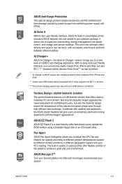
...ASUS Exclusive Features ASUS TurboV Feel the adrenaline rush of the button to connect easily with next-generation components and peripherals, USB 3.0 transfers data 10x faster and is also backward compatible with USB 2.0 components. 100% All High-quality Conductive Polymer Capacitors This motherboard...allows higher antialiasing, anisotropic filtering, shading, and texture settings. and its user-friendly interface makes overclock with the ASUS TurboV. Moreover, the ASUS OC profiles in different scenarios. Users can easily navigate the new UEFI BIOS with a real-time 3D-rendered ...
...ASUS Exclusive Features ASUS TurboV Feel the adrenaline rush of the button to connect easily with next-generation components and peripherals, USB 3.0 transfers data 10x faster and is also backward compatible with USB 2.0 components. 100% All High-quality Conductive Polymer Capacitors This motherboard...allows higher antialiasing, anisotropic filtering, shading, and texture settings. and its user-friendly interface makes overclock with the ASUS TurboV. Moreover, the ASUS OC profiles in different scenarios. Users can easily navigate the new UEFI BIOS with a real-time 3D-rendered ...
User Manual
Page 15
... voltage and sensor readings. The built-in variety of useful profiles offer flexible controls of USB3.0 fast charging experience. ASUS F1A55 1-3 Ai Charger+ ASUS Ai Charger+, the latest Ai Charger* version, brings you to a new level of fan speed to achieve a quiet and ...With its easy and user-friendly interface, you to switch back and forth between different utilities. ASUS Anti-Surge Protection This special design protects expensive devices and the motherboard from damage caused by different climate conditions in -one simple to use software package. Fanless ...
... voltage and sensor readings. The built-in variety of useful profiles offer flexible controls of USB3.0 fast charging experience. ASUS F1A55 1-3 Ai Charger+ ASUS Ai Charger+, the latest Ai Charger* version, brings you to a new level of fan speed to achieve a quiet and ...With its easy and user-friendly interface, you to switch back and forth between different utilities. ASUS Anti-Surge Protection This special design protects expensive devices and the motherboard from damage caused by different climate conditions in -one simple to use software package. Fanless ...
User Manual
Page 16
...the product and thus mitigate environmental impacts. 1.4 Before you proceed Take note of the following precautions before you install motherboard components or change any motherboard settings. • Unplug the power cord from the wall socket before touching any component. • Before handling ...using the bundled support DVD or a USB flash disk that contains the BIOS file. ASUS CrashFree BIOS 3 ASUS CrashFree BIOS 3 is an auto-recovery tool that allows you to the motherboard, peripherals, or components. 1-4 Chapter 1: Product introduction feature automatically restores the CPU default...
...the product and thus mitigate environmental impacts. 1.4 Before you proceed Take note of the following precautions before you install motherboard components or change any motherboard settings. • Unplug the power cord from the wall socket before touching any component. • Before handling ...using the bundled support DVD or a USB flash disk that contains the BIOS file. ASUS CrashFree BIOS 3 ASUS CrashFree BIOS 3 is an auto-recovery tool that allows you to the motherboard, peripherals, or components. 1-4 Chapter 1: Product introduction feature automatically restores the CPU default...
User Manual
Page 17
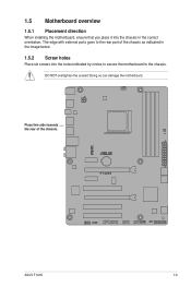
Place this side towards the rear of the chassis as indicated in the correct orientation. F1A55 ASUS F1A55 1-5 Doing so can damage the motherboard. DO NOT overtighten the screws! The edge with external ports goes to the chassis. 1.5 Motherboard overview 1.5.1 Placement direction When installing the motherboard, ensure that you place it into the chassis in the image below. 1.5.2 Screw holes Place six screws into the holes indicated by circles to secure the motherboard to the rear part of the chassis.
Place this side towards the rear of the chassis as indicated in the correct orientation. F1A55 ASUS F1A55 1-5 Doing so can damage the motherboard. DO NOT overtighten the screws! The edge with external ports goes to the chassis. 1.5 Motherboard overview 1.5.1 Placement direction When installing the motherboard, ensure that you place it into the chassis in the image below. 1.5.2 Screw holes Place six screws into the holes indicated by circles to secure the motherboard to the rear part of the chassis.
User Manual
Page 18
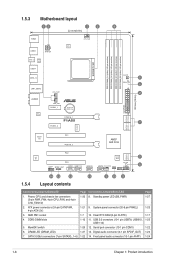
1.5.3 Motherboard layout 12 1 3 22.4cm(8.8in) KBMS USB56 ATX12V CPU_FAN EPU SPDIF_O2 ASM 1042 USB34 SOCKET FM1 USB3_12 LAN1_USB12 AUDIO RTL 8111E CHA_FAN1 PWR_FAN PCIEX1_1 Lithium Cell CMOS Power PCIEX1_2 PCIEX16_1 F1A55 DDR3 DIMM_A1 (64bit, 240-pin module) DDR3 DIMM_A2 (64bit, 240-pin module) DDR3 DIMM_B1 (64bit, 240-pin module) DDR3 DIMM_B2 (64bit...
1.5.3 Motherboard layout 12 1 3 22.4cm(8.8in) KBMS USB56 ATX12V CPU_FAN EPU SPDIF_O2 ASM 1042 USB34 SOCKET FM1 USB3_12 LAN1_USB12 AUDIO RTL 8111E CHA_FAN1 PWR_FAN PCIEX1_1 Lithium Cell CMOS Power PCIEX1_2 PCIEX16_1 F1A55 DDR3 DIMM_A1 (64bit, 240-pin module) DDR3 DIMM_A2 (64bit, 240-pin module) DDR3 DIMM_B1 (64bit, 240-pin module) DDR3 DIMM_B2 (64bit...
User Manual
Page 19
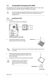
... accelerated processors with a small triangle. 4. Locate the FM1 socket on the motherboard. Socket lever Ensure that the APU corner with the gold triangle matches the socket corner with AMD® Radeon™ HD 6000 series graphics. Small triangle Gold triangle ASUS F1A55 1-7 F1A55 F1A55 processor socket FM1 2. Carefully insert the APU into the socket until...
... accelerated processors with a small triangle. 4. Locate the FM1 socket on the motherboard. Socket lever Ensure that the APU corner with the gold triangle matches the socket corner with AMD® Radeon™ HD 6000 series graphics. Small triangle Gold triangle ASUS F1A55 1-7 F1A55 F1A55 processor socket FM1 2. Carefully insert the APU into the socket until...
User Manual
Page 20
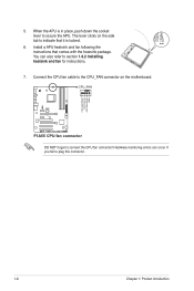
CPU_FAN F1A55 F1A55 CPU fan connector DO NOT forget to section 1.6.2 Installing heatsink and fan for instructions. 7. Install a APU heatsink and fan following the instructions that it is in place, push down the socket lever to indicate that comes with the heatsink package. The lever clicks on the motherboard. You can occur if you...
CPU_FAN F1A55 F1A55 CPU fan connector DO NOT forget to section 1.6.2 Installing heatsink and fan for instructions. 7. Install a APU heatsink and fan following the instructions that it is in place, push down the socket lever to indicate that comes with the heatsink package. The lever clicks on the motherboard. You can occur if you...
User Manual
Page 21
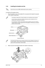
...module base. 1 2 3 4 5 ASUS F1A55 1-9 To install the CPU heatsink and fan: 1. If the instructions in this section do not have to the CPU heatsink or CPU before you use only AMD-certified heatsink and fan assembly. Place the heatsink on the motherboard upon purchase. • You do ...module base. • The retention module base is properly applied to remove the retention module base when installing the CPU or installing other motherboard components. • If you purchased a separate CPU heatsink and fan assembly, ensure that you install the heatsink and fan assembly. CPU...
...module base. 1 2 3 4 5 ASUS F1A55 1-9 To install the CPU heatsink and fan: 1. If the instructions in this section do not have to the CPU heatsink or CPU before you use only AMD-certified heatsink and fan assembly. Place the heatsink on the motherboard upon purchase. • You do ...module base. • The retention module base is properly applied to remove the retention module base when installing the CPU or installing other motherboard components. • If you purchased a separate CPU heatsink and fan assembly, ensure that you install the heatsink and fan assembly. CPU...
User Manual
Page 22
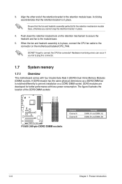
...the retention module base. The figure illustrates the location of the retention bracket to plug this connector. 1.7 System memory 1.7.1 Overview This motherboard comes with less power consumption. When the fan and heatsink assembly is notched differently to connect the CPU fan connector! DO NOT forget ... Inline Memory Modules (DIMM) sockets. Align the other end of the DDR3 DIMM sockets: DIMM_A1 DIMM_A2 DIMM_B1 DIMM_B2 Channel Sockets F1A55 Channel A DIMM_A1 and DIMM_A2 Channel B DIMM_B1 and DIMM_B2 F1A55 240-pin DDR3 DIMM sockets 1-10 Chapter 1: Product introduction 3.
...the retention module base. The figure illustrates the location of the retention bracket to plug this connector. 1.7 System memory 1.7.1 Overview This motherboard comes with less power consumption. When the fan and heatsink assembly is notched differently to connect the CPU fan connector! DO NOT forget ... Inline Memory Modules (DIMM) sockets. Align the other end of the DDR3 DIMM sockets: DIMM_A1 DIMM_A2 DIMM_B1 DIMM_B2 Channel Sockets F1A55 Channel A DIMM_A1 and DIMM_A2 Channel B DIMM_B1 and DIMM_B2 F1A55 240-pin DDR3 DIMM sockets 1-10 Chapter 1: Product introduction 3.
User Manual
Page 23
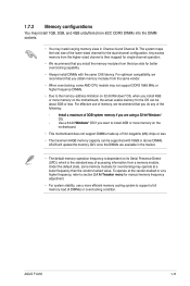
... DIMM sockets. • You may operate at a higher frequency, refer to support a full memory load (4 DIMMs) or overclocking condition. ASUS F1A55 1-11 For optimum compatibility, we recommend that you do any of the following: I�n�s�ta�l�l�a��m�... To operate at the vendor-marked or at a lower frequency than the vendor-marked value. For effective use a more memory on the motherboard, the actual usable memory for the dual-channel configuration. The system maps the total size of 512 megabits (Mb) chips or less. ...
... DIMM sockets. • You may operate at a higher frequency, refer to support a full memory load (4 DIMMs) or overclocking condition. ASUS F1A55 1-11 For optimum compatibility, we recommend that you do any of the following: I�n�s�ta�l�l�a��m�... To operate at the vendor-marked or at a lower frequency than the vendor-marked value. For effective use a more memory on the motherboard, the actual usable memory for the dual-channel configuration. The system maps the total size of 512 megabits (Mb) chips or less. ...
User Manual
Page 24
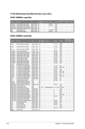
... OCZ3G1866LV4GK 4GB(2 x 2GB) DS - - 10-10-10-27 1.65V • OCZ OCZ3P1866C9LV6GK 6GB(3 x 2GB) DS - - 9-9-9-28 1.65V • • DDR3-1600MHz capability Vendors Part No. F1A55 Motherboard Qualified Vendors Lists (QVL) DDR3-1866MHz capability Vendors Part No.
... OCZ3G1866LV4GK 4GB(2 x 2GB) DS - - 10-10-10-27 1.65V • OCZ OCZ3P1866C9LV6GK 6GB(3 x 2GB) DS - - 9-9-9-28 1.65V • • DDR3-1600MHz capability Vendors Part No. F1A55 Motherboard Qualified Vendors Lists (QVL) DDR3-1866MHz capability Vendors Part No.
User Manual
Page 27
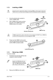
Simultaneously press the retaining clips outward to avoid damaging the DIMM. 3. DIMM notch ASUS F1A55 1-15 Press the retaining clips outward to both the motherboard and the components. 1. DO NOT force a DIMM into the socket until the retaining clips snap back in place 3 and the DIMM is keyed with a notch ...
Simultaneously press the retaining clips outward to avoid damaging the DIMM. 3. DIMM notch ASUS F1A55 1-15 Press the retaining clips outward to both the motherboard and the components. 1. DO NOT force a DIMM into the socket until the retaining clips snap back in place 3 and the DIMM is keyed with a notch ...
User Manual
Page 28
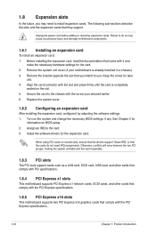
...the necessary hardware settings for information on the system and change the necessary BIOS settings, if any. Remove the system unit cover (if your motherboard is completely seated on shared slots, ensure that the drivers support "Share IRQ" or that the cards do so may need IRQ assignments. ... cards such as a LAN card, SCSI card, USB card, and other cards that comply with PCI specifications. 1.8.4 PCI Express x1 slots This motherboard supports PCI Express x1 network cards, SCSI cards, and other cards that comply with the PCI Express specifications. 1.8.5 PCI Express x16 slots This...
...the necessary hardware settings for information on the system and change the necessary BIOS settings, if any. Remove the system unit cover (if your motherboard is completely seated on shared slots, ensure that the drivers support "Share IRQ" or that the cards do so may need IRQ assignments. ... cards such as a LAN card, SCSI card, USB card, and other cards that comply with PCI specifications. 1.8.4 PCI Express x1 slots This motherboard supports PCI Express x1 network cards, SCSI cards, and other cards that comply with the PCI Express specifications. 1.8.5 PCI Express x16 slots This...
User Manual
Page 29
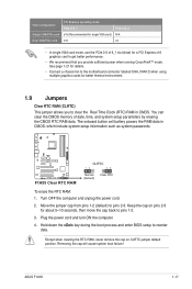
... jumper allows you provide sufficient power when running CrossFireX™ mode. Hold down the key during the boot process and enter BIOS setup to pins 2-3. ASUS F1A55 1-17 The onboard button cell battery powers the RAM data in CMOS. Move the jumper cap from pins 1-2 (default) to reenter data. Keep the ... (RTC) RAM in CMOS, which include system setup information such as system passwords. See page 1-21 for details. • Connect a chassis fan to the motherboard connector labeled CHA_FAN1/2 when using multiple graphics cards for a PCI Express x16 graphics card to pins 1-2. 3.
... jumper allows you provide sufficient power when running CrossFireX™ mode. Hold down the key during the boot process and enter BIOS setup to pins 2-3. ASUS F1A55 1-17 The onboard button cell battery powers the RAM data in CMOS. Move the jumper cap from pins 1-2 (default) to reenter data. Keep the ... (RTC) RAM in CMOS, which include system setup information such as system passwords. See page 1-21 for details. • Connect a chassis fan to the motherboard connector labeled CHA_FAN1/2 when using multiple graphics cards for a PCI Express x16 graphics card to pins 1-2. 3.
User Manual
Page 32
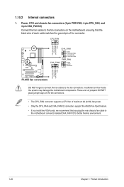
...ground pin of maximum 2A (24 W) fan power. • Only the CPU_FAN and CHA_FAN1/2 connectors support the ASUS Fan Xpert feature. • If you plug the rear chassis fan cable to the motherboard connector labeled CHA_FAN1/2 for better thermal environment. 1-20 Chapter 1: Product introduction Power, CPU and chassis fan connectors ...CPU FAN PWR GND CHA_FAN1 GND CHA FAN PWR CHA FAN IN CHA FAN PWM PWR_FAN CHA_FAN2 GND +12V F1A55 Rotation CHA FAN PWM CHA FAN IN CHA FAN PWR GND F1A55 fan connectors DO NOT forget to connect the fan cables to the fan connectors on the fan connectors. ...
...ground pin of maximum 2A (24 W) fan power. • Only the CPU_FAN and CHA_FAN1/2 connectors support the ASUS Fan Xpert feature. • If you plug the rear chassis fan cable to the motherboard connector labeled CHA_FAN1/2 for better thermal environment. 1-20 Chapter 1: Product introduction Power, CPU and chassis fan connectors ...CPU FAN PWR GND CHA_FAN1 GND CHA FAN PWR CHA FAN IN CHA FAN PWM PWR_FAN CHA_FAN2 GND +12V F1A55 Rotation CHA FAN PWM CHA FAN IN CHA FAN PWR GND F1A55 fan connectors DO NOT forget to connect the fan cables to the fan connectors on the fan connectors. ...


