User Manual
Page 13
...-leading visual experience. Chapter 1 Product introduction 1.1 Welcome! series accelerated processor with AMD® Radeon™ HD 6000 series graphics This motherboard supports AMD® A- & E2- ASUS F1A55 1-1 Thank you start installing the motherboard, and hardware devices on it another standout in one small, energy-efficient design to 5GT/s.
...-leading visual experience. Chapter 1 Product introduction 1.1 Welcome! series accelerated processor with AMD® Radeon™ HD 6000 series graphics This motherboard supports AMD® A- & E2- ASUS F1A55 1-1 Thank you start installing the motherboard, and hardware devices on it another standout in one small, energy-efficient design to 5GT/s.
User Manual
Page 15
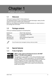
... is a user-friendly utility that offers users a noiseless PC environment. ASUS MyLogo 2™ Turn your system. Ai Charger+ ASUS Ai Charger+, the latest Ai Charger* version, brings you to use software package. ASUS F1A55 1-3 It allows you to update the BIOS without using a bootable floppy... disk or an OS-based utility. Fan Xpert ASUS Fan Xpert intelligently allows you to a new level of USB3.0 fast charging experience. ASUS Anti-Surge Protection This special...
... is a user-friendly utility that offers users a noiseless PC environment. ASUS MyLogo 2™ Turn your system. Ai Charger+ ASUS Ai Charger+, the latest Ai Charger* version, brings you to use software package. ASUS F1A55 1-3 It allows you to update the BIOS without using a bootable floppy... disk or an OS-based utility. Fan Xpert ASUS Fan Xpert intelligently allows you to a new level of USB3.0 fast charging experience. ASUS Anti-Surge Protection This special...
User Manual
Page 17
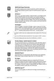
Place this side towards the rear of the chassis as indicated in the image below. 1.5.2 Screw holes Place six screws into the chassis in the correct orientation. DO NOT overtighten the screws! Doing so can damage the motherboard. F1A55 ASUS F1A55 1-5 1.5 Motherboard overview 1.5.1 Placement direction When installing the motherboard, ensure that you place it into the holes indicated by circles to secure the motherboard to the chassis. The edge with external ports goes to the rear part of the chassis.
Place this side towards the rear of the chassis as indicated in the image below. 1.5.2 Screw holes Place six screws into the chassis in the correct orientation. DO NOT overtighten the screws! Doing so can damage the motherboard. F1A55 ASUS F1A55 1-5 1.5 Motherboard overview 1.5.1 Placement direction When installing the motherboard, ensure that you place it into the holes indicated by circles to secure the motherboard to the chassis. The edge with external ports goes to the rear part of the chassis.
User Manual
Page 19
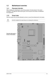
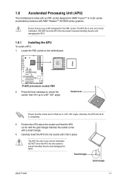
... in only one correct orientation. otherwise, the APU will not fit in one correct orientation. The APU fits only in completely. 3. Small triangle Gold triangle ASUS F1A55 1-7 F1A55 F1A55 processor socket FM1 2. series accelerated processors with a small triangle. 4. Ensure that the socket lever is lifted up to a 90°-100° angle; 1.6 Accelerated Processing...
... in only one correct orientation. otherwise, the APU will not fit in one correct orientation. The APU fits only in completely. 3. Small triangle Gold triangle ASUS F1A55 1-7 F1A55 F1A55 processor socket FM1 2. series accelerated processors with a small triangle. 4. Ensure that the socket lever is lifted up to a 90°-100° angle; 1.6 Accelerated Processing...
User Manual
Page 21
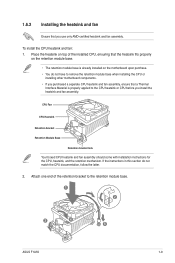
... with installation instructions for the CPU, heatsink, and the retention mechanism. If the instructions in this section do not have to the retention module base. 1 2 3 4 5 ASUS F1A55 1-9 To install the CPU heatsink and fan: 1. Attach one end of the installed CPU, ensuring that the heatsink fits properly on the retention module base...
... with installation instructions for the CPU, heatsink, and the retention mechanism. If the instructions in this section do not have to the retention module base. 1 2 3 4 5 ASUS F1A55 1-9 To install the CPU heatsink and fan: 1. Attach one end of the installed CPU, ensuring that the heatsink fits properly on the retention module base...
User Manual
Page 23
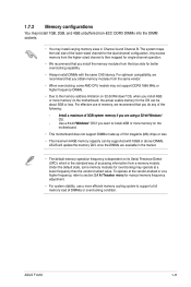
...or more memory on the motherboard, the actual usable memory for better overclocking capability. • Always install DIMMs with 16GB or above DIMMs. ASUS will update the memory QVL once the DIMMs are available in the market. • The default memory operation frequency is dependent on the ...made up of 512 megabits (Mb) chips or less. • The maximum 64GB memory capacity can be supported with the same CAS latency. ASUS F1A55 1-11 Under the default state, some AMD CPU models may not support DDR3 1866 MHz or higher frequency DIMMs. • Due to support a...
...or more memory on the motherboard, the actual usable memory for better overclocking capability. • Always install DIMMs with 16GB or above DIMMs. ASUS will update the memory QVL once the DIMMs are available in the market. • The default memory operation frequency is dependent on the ...made up of 512 megabits (Mb) chips or less. • The maximum 64GB memory capacity can be supported with the same CAS latency. ASUS F1A55 1-11 Under the default state, some AMD CPU models may not support DDR3 1866 MHz or higher frequency DIMMs. • Due to support a...
User Manual
Page 25
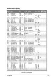
...; PSC AL7F8G73F-DJ2 1GB SS PSC A3P1GF3FGF - - • • • PSC AL8F8G73F-DJ2 2GB DS PSC A3P1GF3FGF - - • • • (continued on the next page) ASUS F1A55 1-13 DDR3-1333MHz capability Vendors Part No. Size SS/ Chip DS Brand Chip NO.
...; PSC AL7F8G73F-DJ2 1GB SS PSC A3P1GF3FGF - - • • • PSC AL8F8G73F-DJ2 2GB DS PSC A3P1GF3FGF - - • • • (continued on the next page) ASUS F1A55 1-13 DDR3-1333MHz capability Vendors Part No. Size SS/ Chip DS Brand Chip NO.
User Manual
Page 27
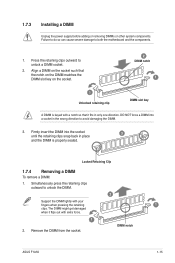
...: 1. Simultaneously press the retaining clips outward to unlock a DIMM socket. 2. Failure to do so can cause severe damage to avoid damaging the DIMM. 3. DIMM notch ASUS F1A55 1-15
...: 1. Simultaneously press the retaining clips outward to unlock a DIMM socket. 2. Failure to do so can cause severe damage to avoid damaging the DIMM. 3. DIMM notch ASUS F1A55 1-15
User Manual
Page 29
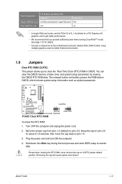
... seconds, then move the cap back to clear the Real Time Clock (RTC) RAM in CMOS, which include system setup information such as system passwords. ASUS F1A55 1-17 F1A55 F1A55 Clear RTC RAM CLRTC 12 23 Normal (Default) Clear RTC To erase the RTC RAM: 1. Plug the power cord and turn ON the computer...
... seconds, then move the cap back to clear the Real Time Clock (RTC) RAM in CMOS, which include system setup information such as system passwords. ASUS F1A55 1-17 F1A55 F1A55 Clear RTC RAM CLRTC 12 23 Normal (Default) Clear RTC To erase the RTC RAM: 1. Plug the power cord and turn ON the computer...
User Manual
Page 31
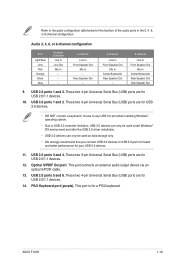
... Speaker Out - 8-channel Line In Front Speaker Out Mic In Center/Subwoofer Rear Speaker Out Side Speaker Out 9. Optical S/PDIF Out port. USB 3.0 ports 1 and 2. ASUS F1A55 1-19 These two 4-pin Universal Serial Bus (USB) ports are for the function of the audio ports in the 2, 4, 6, or 8-channel configuration. USB 2.0 ports 3 and...
... Speaker Out - 8-channel Line In Front Speaker Out Mic In Center/Subwoofer Rear Speaker Out Side Speaker Out 9. Optical S/PDIF Out port. USB 3.0 ports 1 and 2. ASUS F1A55 1-19 These two 4-pin Universal Serial Bus (USB) ports are for the function of the audio ports in the 2, 4, 6, or 8-channel configuration. USB 2.0 ports 3 and...
User Manual
Page 33
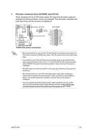
... devices. Otherwise, the system will not boot up if the power is inadequate. • DO NOT forget to fit these connectors in only one orientation. ASUS F1A55 1-21 The plugs from the power supply are for details. This PSU type has 24-pin and 4-pin power plugs. • If you use a PSU... with 20-pin and 4-pin power plugs, ensure that the 20-pin power plug can provide at http://support.asus. ATX12V EATXPWR F1A55 GND GND PIN 1 F1A55 ATX power connectors +12V DC +3 Volts +12V DC +12 Volts +12 Volts +5V Standby Power OK GND +5 Volts GND +5 Volts GND +3 Volts...
... devices. Otherwise, the system will not boot up if the power is inadequate. • DO NOT forget to fit these connectors in only one orientation. ASUS F1A55 1-21 The plugs from the power supply are for details. This PSU type has 24-pin and 4-pin power plugs. • If you use a PSU... with 20-pin and 4-pin power plugs, ensure that the 20-pin power plug can provide at http://support.asus. ATX12V EATXPWR F1A55 GND GND PIN 1 F1A55 ATX power connectors +12V DC +3 Volts +12V DC +12 Volts +12 Volts +5V Standby Power OK GND +5 Volts GND +5 Volts GND +3 Volts...
User Manual
Page 35
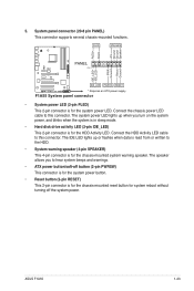
... panel connector (20-8 pin PANEL) This connector supports several chassis-mounted functions. PWR Ground Reset Ground PANEL PIN 1 F1A55 IDE_LED PWRSW RESET * Requires an ATX power supply F1A55 System panel connector • System power LED (2-pin PLED) This 2-pin connector is for the HDD Activity LED. The... system power LED lights up or flashes when data is for system reboot without turning off the system power. 5. ASUS F1A55 1-23 PLED SPEAKER PLED+ PLED+5V Ground Ground Speaker IDE_LED+ IDE_LED- Connect the HDD Activity LED cable to the HDD. • System...
... panel connector (20-8 pin PANEL) This connector supports several chassis-mounted functions. PWR Ground Reset Ground PANEL PIN 1 F1A55 IDE_LED PWRSW RESET * Requires an ATX power supply F1A55 System panel connector • System power LED (2-pin PLED) This 2-pin connector is for the HDD Activity LED. The... system power LED lights up or flashes when data is for system reboot without turning off the system power. 5. ASUS F1A55 1-23 PLED SPEAKER PLED+ PLED+5V Ground Ground Speaker IDE_LED+ IDE_LED- Connect the HDD Activity LED cable to the HDD. • System...
User Manual
Page 37
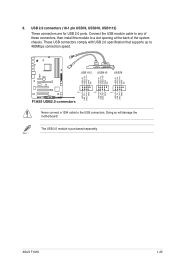
.... USB1112 USB910 USB78 USB+5V USB_P12USB_P12+ GND NC USB+5V USB_P10USB_P10+ GND NC USB+5V USB_P8USB_P8+ GND NC F1A55 USB+5V USB_P11USB_P11+ GND USB+5V USB_P9USB_P9+ GND USB+5V USB_P7USB_P7+ GND PIN 1 PIN 1 PIN 1 F1A55 USB2.0 connectors Never connect a 1394 cable to 480Mbps connection speed. The USB 2.0 module is purchased separately. USB... 2.0 ports. Connect the USB module cable to any of these connectors, then install the module to a slot opening at the back of the system chassis. ASUS F1A55 1-25 8. Doing so will damage the motherboard!
.... USB1112 USB910 USB78 USB+5V USB_P12USB_P12+ GND NC USB+5V USB_P10USB_P10+ GND NC USB+5V USB_P8USB_P8+ GND NC F1A55 USB+5V USB_P11USB_P11+ GND USB+5V USB_P9USB_P9+ GND USB+5V USB_P7USB_P7+ GND PIN 1 PIN 1 PIN 1 F1A55 USB2.0 connectors Never connect a 1394 cable to 480Mbps connection speed. The USB 2.0 module is purchased separately. USB... 2.0 ports. Connect the USB module cable to any of these connectors, then install the module to a slot opening at the back of the system chassis. ASUS F1A55 1-25 8. Doing so will damage the motherboard!
User Manual
Page 39
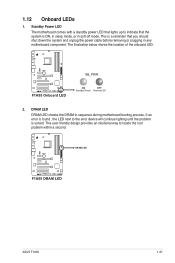
... will continue lighting until the problem is found , the LED next to locate the root problem within a second. SB_PWR F1A55 F1A55 Onboard LED ON OFF Standby Power Powered Off 2. F1A55 DRAM LED F1A55 DRAM LED ASUS F1A55 1-27 Standby Power LED The motherboard comes with a standby power LED that lights up to indicate that you should...
... will continue lighting until the problem is found , the LED next to locate the root problem within a second. SB_PWR F1A55 F1A55 Onboard LED ON OFF Standby Power Powered Off 2. F1A55 DRAM LED F1A55 DRAM LED ASUS F1A55 1-27 Standby Power LED The motherboard comes with a standby power LED that lights up to indicate that you should...
User Manual
Page 42
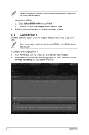
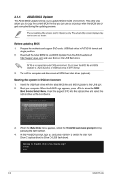
...Locate the BIOS file from file, then click Next. ASUS EZ Flash 2 Utility V01.02 Flash Info MODEL: F1A55 File Path: fs0:\ Drive fs0:\ VER: 0203 Folder Info 05/02/11 03:19p 4194304 Exit DATE: 06/28/2011 F1A55.ROM File Info MODEL: F1A55 Help Info VER: 0203 DATE: 06/28/11 [Enter...] Select or Load [Tab] Switch [Up/Down/PageUp/PageDown/Home/End] Move [Esc] Exit [F2] Backup 2-2 ASUS F1A55 Select Update BIOS from the Open window, then click Open. 3. Enter the Advanced Mode of updating itself through the Internet. b. To update the BIOS using ...
...Locate the BIOS file from file, then click Next. ASUS EZ Flash 2 Utility V01.02 Flash Info MODEL: F1A55 File Path: fs0:\ Drive fs0:\ VER: 0203 Folder Info 05/02/11 03:19p 4194304 Exit DATE: 06/28/2011 F1A55.ROM File Info MODEL: F1A55 Help Info VER: 0203 DATE: 06/28/11 [Enter...] Select or Load [Tab] Switch [Up/Down/PageUp/PageDown/Home/End] Move [Esc] Exit [F2] Backup 2-2 ASUS F1A55 Select Update BIOS from the Open window, then click Open. 3. Enter the Advanced Mode of updating itself through the Internet. b. To update the BIOS using ...
User Manual
Page 44
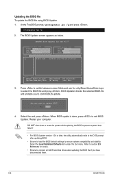
...FreeDOS prompt, type d: and press to switch the disk from the ASUS website at http://support.asus.com and save the BIOS file and BIOS Updater to show the BIOS Boot Device Select Menu. C:\>d: D:\> 2-4 ASUS F1A55 Insert the USB flash drive with the latest BIOS file and BIOS ...Updater to Drive D (USB flash drive). Download the latest BIOS file and BIOS Updater from Drive C (optical drive) to the USB port. 2. 2.1.4 ASUS BIOS Updater The ASUS BIOS Updater allows you can...
...FreeDOS prompt, type d: and press to switch the disk from the ASUS website at http://support.asus.com and save the BIOS file and BIOS Updater to show the BIOS Boot Device Select Menu. C:\>d: D:\> 2-4 ASUS F1A55 Insert the USB flash drive with the latest BIOS file and BIOS ...Updater to Drive D (USB flash drive). Download the latest BIOS file and BIOS Updater from Drive C (optical drive) to the USB port. 2. 2.1.4 ASUS BIOS Updater The ASUS BIOS Updater allows you can...
User Manual
Page 46
Select Yes and press . BIOS Updater checks the selected BIOS file and prompts you have disconnected them. 2-6 ASUS F1A55 When BIOS update is done, press to update BIOS? Refer to confirm BIOS update. Updating the BIOS file To update the BIOS file using BIOS ... after updating the BIOS file if you to section 2.9 Exit menu for DOS V1.07 Current ROM BOARD: F1A55 VER: 0203 DATE: 06/28/2011 Update ROM BOARD: Unknown VER: Unknown DATE: Unknown PATH: A:\ A: F1A55.ROM 4194304 2011-06-28 17:30:48 Note [Enter] Select or Load [Up/Down/Home/End...
Select Yes and press . BIOS Updater checks the selected BIOS file and prompts you have disconnected them. 2-6 ASUS F1A55 When BIOS update is done, press to update BIOS? Refer to confirm BIOS update. Updating the BIOS file To update the BIOS file using BIOS ... after updating the BIOS file if you to section 2.9 Exit menu for DOS V1.07 Current ROM BOARD: F1A55 VER: 0203 DATE: 06/28/2011 Update ROM BOARD: Unknown VER: Unknown DATE: Unknown PATH: A:\ A: F1A55.ROM 4194304 2011-06-28 17:30:48 Note [Enter] Select or Load [Up/Down/Home/End...
User Manual
Page 48
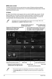
...65533;n� 2.7 Boot menu for details. You can be used under two modes: EZ Mode and Advanced Mode. EZ Mode Friday [10/08/2010] F1A55 BIOS Version : 0203 CPU Type : AMD Engineering Sample Total Memory : 1024 MB (DDR3 1066MHz) Exit/Advanced Mode Build Date : 06/28/2011 ...CHA_FAN2 N/A Q-Fan Control Quiet Performance Boot Priority Energy Saving Normal Use the mouse to drag or keyboard to navigate to the system. 2-8 ASUS F1A55 Boot Menu(F8) Default(F5) Selects the boot device priority Silent mode Loads optimized default Displays the system properties of the selected mode ...
...65533;n� 2.7 Boot menu for details. You can be used under two modes: EZ Mode and Advanced Mode. EZ Mode Friday [10/08/2010] F1A55 BIOS Version : 0203 CPU Type : AMD Engineering Sample Total Memory : 1024 MB (DDR3 1066MHz) Exit/Advanced Mode Build Date : 06/28/2011 ...CHA_FAN2 N/A Q-Fan Control Quiet Performance Boot Priority Energy Saving Normal Use the mouse to drag or keyboard to navigate to the system. 2-8 ASUS F1A55 Boot Menu(F8) Default(F5) Selects the boot device priority Silent mode Loads optimized default Displays the system properties of the selected mode ...
User Manual
Page 50
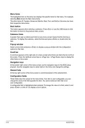
... can change the settings. Pop-up window Select a menu item and press to select items in the menu and change the value of options. 2-10 ASUS F1A55 A configurable field is a brief description of the menu screen are items that menu. To display the submenu, select the item and press or double-click...
... can change the settings. Pop-up window Select a menu item and press to select items in the menu and change the value of options. 2-10 ASUS F1A55 A configurable field is a brief description of the menu screen are items that menu. To display the submenu, select the item and press or double-click...
User Manual
Page 52
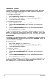
... Password item on top of the screen shows the default Not Installed. The User Password item on top of the screen shows Not Installed. 2-12 ASUS F1A55 Select the User Password item and press . 2. From the Create New Password box, key in the BIOS setup program. To clear the user password, follow...
... Password item on top of the screen shows the default Not Installed. The User Password item on top of the screen shows Not Installed. 2-12 ASUS F1A55 Select the User Password item and press . 2. From the Create New Password box, key in the BIOS setup program. To clear the user password, follow...


