
CUSI-FX User Manual
Page 4
... (CPU 22 3.7 Expansion Cards 23 3.7.1 Expansion Card Installation Procedure 23 3.7.2 Assigning IRQs for Expansion Cards 23 3.7.3 Audio Modem Riser (AMR) Slot 25 3.8 Connectors 26 3.9 Starting Up the First Time 39 4. FEATURES 8 2.1 The ASUS CUSI-FX 8 2.1.1 Specifications 8 2.1.2 Specifications-Optional Components 9 2.1.3 Performance 10 2.1.4 Intelligence 11 2.2 CUSI-FX Motherboard Components 12 3. BIOS SETUP 41 4.1 Managing and Updating Your BIOS 41 4.1.1 Upon First Use of the Computer System 41 4.1.2 Updating BIOS Procedures 42 4.2 BIOS Setup Program 45 4.2.1 BIOS Menu...
... (CPU 22 3.7 Expansion Cards 23 3.7.1 Expansion Card Installation Procedure 23 3.7.2 Assigning IRQs for Expansion Cards 23 3.7.3 Audio Modem Riser (AMR) Slot 25 3.8 Connectors 26 3.9 Starting Up the First Time 39 4. FEATURES 8 2.1 The ASUS CUSI-FX 8 2.1.1 Specifications 8 2.1.2 Specifications-Optional Components 9 2.1.3 Performance 10 2.1.4 Intelligence 11 2.2 CUSI-FX Motherboard Components 12 3. BIOS SETUP 41 4.1 Managing and Updating Your BIOS 41 4.1.1 Upon First Use of the Computer System 41 4.1.2 Updating BIOS Procedures 42 4.2 BIOS Setup Program 45 4.2.1 BIOS Menu...

CUSI-FX User Manual
Page 8
... The ASUS CUSI-FX motherboard is carefully designed for more peripheral connectivity options. • Peripheral Wakeup: Supports Wakeup on two channels. UART2 can support Bus Master PCI cards, such as SCSI or LAN cards. (PCI supports up to 1GB. • UltraDMA/66 Support: Comes with an onboard PCI Bus Master IDE controller with two connectors that support four IDE devices on LAN, USB, and PS/2 Mouse/Keyboard. • SMBus: Features the System Management...
... The ASUS CUSI-FX motherboard is carefully designed for more peripheral connectivity options. • Peripheral Wakeup: Supports Wakeup on two channels. UART2 can support Bus Master PCI cards, such as SCSI or LAN cards. (PCI supports up to 1GB. • UltraDMA/66 Support: Comes with an onboard PCI Bus Master IDE controller with two connectors that support four IDE devices on LAN, USB, and PS/2 Mouse/Keyboard. • SMBus: Features the System Management...

CUSI-FX User Manual
Page 11
... and driver support. • Peripheral Power Up: Keyboard power up to ensure proper system configuration and management. • System Resources Alert: Today's operating systems, such as information providers. All the fans are used up can be monitored for RPM and failure. Suggestions will warn the user before the system resources are set for future processors, so monitoring is necessary to prevent possible application crashes. ASUS CUSI-FX User's Manual...
... and driver support. • Peripheral Power Up: Keyboard power up to ensure proper system configuration and management. • System Resources Alert: Today's operating systems, such as information providers. All the fans are used up can be monitored for RPM and failure. Suggestions will warn the user before the system resources are set for future processors, so monitoring is necessary to prevent possible application crashes. ASUS CUSI-FX User's Manual...

CUSI-FX User Manual
Page 12
...VGA Monitor Output Connector 17 1 Serial COM1 Port Connectors Bottom) 19 1 PS/2 Mouse Connector Top) 21 1 PS/2 Keyboard Connector Bottom) 21 Audio Cmedia 8738 PCI Audio Chipset (optional 15 1 Game/MIDI Connector (on audio model only Top) 16 1 Line Out Connector (on audio model only) ........ (Bottom) 16 1 Line In Connector (on audio model only Bottom) 16 1 Microphone Connector (on audio model only) ... (Bottom) 16 Network Features SiS630E Ethernet Controller 1 LAN (RJ45) Connector (optional Top) 20 Wake-On-LAN Connector 9 Wake-On-Ring Connector 1 Power ATX Power Supply Connector...
...VGA Monitor Output Connector 17 1 Serial COM1 Port Connectors Bottom) 19 1 PS/2 Mouse Connector Top) 21 1 PS/2 Keyboard Connector Bottom) 21 Audio Cmedia 8738 PCI Audio Chipset (optional 15 1 Game/MIDI Connector (on audio model only Top) 16 1 Line Out Connector (on audio model only) ........ (Bottom) 16 1 Line In Connector (on audio model only Bottom) 16 1 Microphone Connector (on audio model only) ... (Bottom) 16 Network Features SiS630E Ethernet Controller 1 LAN (RJ45) Connector (optional Top) 20 Wake-On-LAN Connector 9 Wake-On-Ring Connector 1 Power ATX Power Supply Connector...

CUSI-FX User Manual
Page 15
... Motherboard Settings 1) JEN p.16 JumperFree Mode Setting (Enable/Disable) 2) USBPWR0/USBPWR1 p.17 USB Power Up Settings (Enable/Disable) 3) FS3, FS1, FS2, FS0 p.18 CPU External Frequency Selection Expansion Slots 1) DIMM1, DIMM2 p.20 168-Pin DIMM Memory Support 2) Socket 370 p.22 Central Processing Unit (CPU) 3) PCI1, PCI2 p.23 32-bit PCI Bus Expansion Slots 4) AMR p.25 Audio Modem Riser Slot Connectors 1) PS2KBMS p.26 PS/2 Mouse Connector (6-pin female) 2) PS2KBMS p.26 PS/2 Keyboard Connector (6-pin female) 3) RJ-45 p.27 Fast-Ethernet Port Connector (optional) 4) USB...
... Motherboard Settings 1) JEN p.16 JumperFree Mode Setting (Enable/Disable) 2) USBPWR0/USBPWR1 p.17 USB Power Up Settings (Enable/Disable) 3) FS3, FS1, FS2, FS0 p.18 CPU External Frequency Selection Expansion Slots 1) DIMM1, DIMM2 p.20 168-Pin DIMM Memory Support 2) Socket 370 p.22 Central Processing Unit (CPU) 3) PCI1, PCI2 p.23 32-bit PCI Bus Expansion Slots 4) AMR p.25 Audio Modem Riser Slot Connectors 1) PS2KBMS p.26 PS/2 Mouse Connector (6-pin female) 2) PS2KBMS p.26 PS/2 Keyboard Connector (6-pin female) 3) RJ-45 p.27 Fast-Ethernet Port Connector (optional) 4) USB...

CUSI-FX User Manual
Page 16
...; Mode Setting JEN Jumperless Mode Jumper Mode 12 12 16 ASUS CUSI-FX User's Manual 3. Unplug your motherboard's function settings through the BIOS setup (see 4.4 Advanced Menu) IMPORTANT: In JumperFree mode, all DIP switches must complete the following steps: • Check Motherboard Settings • Install Memory Modules • Install the Central Processing Unit (CPU) • Install Expansion Cards • Connect Ribbon Cables, Panel Wires, and Power Supply 3.4 Motherboard Settings This section explains in or remove the ATX power connector on the inside. 2. HARDWARE SETUP...
...; Mode Setting JEN Jumperless Mode Jumper Mode 12 12 16 ASUS CUSI-FX User's Manual 3. Unplug your motherboard's function settings through the BIOS setup (see 4.4 Advanced Menu) IMPORTANT: In JumperFree mode, all DIP switches must complete the following steps: • Check Motherboard Settings • Install Memory Modules • Install the Central Processing Unit (CPU) • Install Expansion Cards • Connect Ribbon Cables, Panel Wires, and Power Supply 3.4 Motherboard Settings This section explains in or remove the ATX power connector on the inside. 2. HARDWARE SETUP...

CUSI-FX User Manual
Page 17
... to Enable. 2. Setting USBPWR0/USBPWR1 Enable [1-2] Disable [2-3] (default) 01 USBPWR1 2 1 Enable 3 2 Disable (Default) CUSI-FX CUSI-FX USB Device Wake Up USBPWR0 12 23 Enable Disable (Default) ® 3. These two jumpers must also be set in conjunction with Wake On USB Device in unison; These settings must be set in 4.5.1 Power Up Control. that can supply at least 2A on the +5VSB lead. NOTES: 1. H/W SETUP Motherboard Settings ASUS CUSI-FX User's Manual 17 HARDWARE SETUP 2) USB Device Wake Up (USBPWR0, USBPWR1) These jumpers allow you set to Enable...
... to Enable. 2. Setting USBPWR0/USBPWR1 Enable [1-2] Disable [2-3] (default) 01 USBPWR1 2 1 Enable 3 2 Disable (Default) CUSI-FX CUSI-FX USB Device Wake Up USBPWR0 12 23 Enable Disable (Default) ® 3. These two jumpers must also be set in conjunction with Wake On USB Device in unison; These settings must be set in 4.5.1 Power Up Control. that can supply at least 2A on the +5VSB lead. NOTES: 1. H/W SETUP Motherboard Settings ASUS CUSI-FX User's Manual 17 HARDWARE SETUP 2) USB Device Wake Up (USBPWR0, USBPWR1) These jumpers allow you set to Enable...

CUSI-FX User Manual
Page 23
... necessary hardware or software settings for possible future use , leaving 6 IRQs free for Expansion Cards Some expansion cards need an IRQ to both your power supply when adding or removing expansion cards or other system components. Unplug your motherboard and expansion cards. 3.7.1 Expansion Card Installation Procedure 1. Failure to do so may cause severe damage to operate. If your expansion card. 3.7.2 Assigning IRQs for expansion cards. H/W SETUP Expansion Cards ASUS CUSI-FX User's Manual 23 Install the necessary software drivers...
... necessary hardware or software settings for possible future use , leaving 6 IRQs free for Expansion Cards Some expansion cards need an IRQ to both your power supply when adding or removing expansion cards or other system components. Unplug your motherboard and expansion cards. 3.7.1 Expansion Card Installation Procedure 1. Failure to do so may cause severe damage to operate. If your expansion card. 3.7.2 Assigning IRQs for expansion cards. H/W SETUP Expansion Cards ASUS CUSI-FX User's Manual 23 Install the necessary software drivers...
CUSI-FX User Manual
Page 35
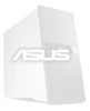
3. If you are not using an ASUS iPanel, you to connect an optional ASUS iPanel, an easy to access drive bay with front I/O ports, status LEDs, and space reserved for a hard disk drive. CUSI-FX AUDIO_PANEL Line out_R AGND3 Line out_L MICPWR Line in_R AGND2 Line in_L AGND MIC2 CUSI-FX Audio Panel Connectors ASUS CUSI-FX User's Manual 35 AFPANEL +5 V IRRX GND IRTX SMBDATA +3VSB SMBCLK LOCKKEY NC...
3. If you are not using an ASUS iPanel, you to connect an optional ASUS iPanel, an easy to access drive bay with front I/O ports, status LEDs, and space reserved for a hard disk drive. CUSI-FX AUDIO_PANEL Line out_R AGND3 Line out_L MICPWR Line in_R AGND2 Line in_L AGND MIC2 CUSI-FX Audio Panel Connectors ASUS CUSI-FX User's Manual 35 AFPANEL +5 V IRRX GND IRTX SMBDATA +3VSB SMBCLK LOCKKEY NC...

CUSI-FX User Manual
Page 37
... the case-mounted key switch to allow you to hear system beeps and warnings. This function requires an ACPI OS and driver support. 24) System Management Interrupt Lead (2-pin SMI) This allows the user to manually place the system into a suspend mode or "Green" mode, where system activity is in use. Only SPEAKER will allow keyboard locking. 22) System Power LED Lead (3-1 pin PWRLED) This 3-1 pin connector connects the system power LED, which lights...
... the case-mounted key switch to allow you to hear system beeps and warnings. This function requires an ACPI OS and driver support. 24) System Management Interrupt Lead (2-pin SMI) This allows the user to manually place the system into a suspend mode or "Green" mode, where system activity is in use. Only SPEAKER will allow keyboard locking. 22) System Power LED Lead (3-1 pin PWRLED) This 3-1 pin connector connects the system power LED, which lights...

CUSI-FX User Manual
Page 39
... the power supply located on test. For ATX power supplies, you turn on the screen. If you do not see anything within 30 seconds from the time you need to your retailer for assistance. 3. HARDWARE SETUP 3.9 Starting Up the First Time 1. Connect the power supply cord into a power outlet that all connections are running at a lower frequency ASUS CUSI-FX User's Manual 39 While the tests are made, close the system case cover. 2. Award BIOS Beep Codes Beep...
... the power supply located on test. For ATX power supplies, you turn on the screen. If you do not see anything within 30 seconds from the time you need to your retailer for assistance. 3. HARDWARE SETUP 3.9 Starting Up the First Time 1. Connect the power supply cord into a power outlet that all connections are running at a lower frequency ASUS CUSI-FX User's Manual 39 While the tests are made, close the system case cover. 2. Award BIOS Beep Codes Beep...
CUSI-FX User Manual
Page 51
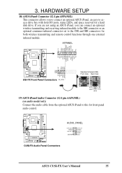
.... NOTE: To make changes to [Manual]. NOTE: To make changes to this feature may not always be set to this field. This feature is automatically configured, the set it manually. Modes 0 through 4 provide successively increased performance. Configuration options: [0] [1] [2] [3] [4] [Disabled] 4. BIOS SETUP Master/Slave Drives ASUS CUSI-FX User's Manual 51 BIOS SETUP Head This field configures the number of the S.M.A.R.T. (Self-Monitoring, Analysis and Reporting Technology) system which utilizes internal hard disk drive monitoring technology. NOTE: To make changes to this...
.... NOTE: To make changes to [Manual]. NOTE: To make changes to this feature may not always be set to this field. This feature is automatically configured, the set it manually. Modes 0 through 4 provide successively increased performance. Configuration options: [0] [1] [2] [3] [4] [Disabled] 4. BIOS SETUP Master/Slave Drives ASUS CUSI-FX User's Manual 51 BIOS SETUP Head This field configures the number of the S.M.A.R.T. (Self-Monitoring, Analysis and Reporting Technology) system which utilizes internal hard disk drive monitoring technology. NOTE: To make changes to this...
CUSI-FX User Manual
Page 54
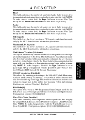
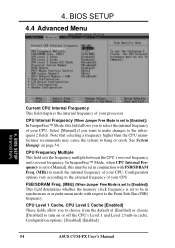
... Jumper Free Mode is set to [Enabled]) This field determines whether the memory clock frequency is set to [Manual], this field allows you to the subsequent 2 fields. BIOS SETUP 4.4 Advanced Menu 4. BIOS SETUP Advanced Menu Current CPU Internal Frequency This field displays the internal frequency of your CPU. In JumperFree™ Mode, when CPU Internal Frequency is set in cache. CPU Level 1 Cache, CPU Level 2 Cache [Enabled] These fields allow you want to make changes to select the internal...
... Jumper Free Mode is set to [Enabled]) This field determines whether the memory clock frequency is set to [Manual], this field allows you to the subsequent 2 fields. BIOS SETUP 4.4 Advanced Menu 4. BIOS SETUP Advanced Menu Current CPU Internal Frequency This field displays the internal frequency of your CPU. In JumperFree™ Mode, when CPU Internal Frequency is set in cache. CPU Level 1 Cache, CPU Level 2 Cache [Enabled] These fields allow you want to make changes to select the internal...
CUSI-FX User Manual
Page 61
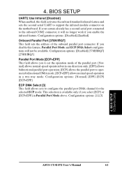
... available only if you to support the infrared module connector on the motherboard. BIOS SETUP I/O Device Config ASUS CUSI-FX User's Manual 61 If your system already has a second serial port connected to operate in bidirectional DMA mode; [ECP+EPP] allows normal speed operation in Parallel Port Mode above. Configuration options: [1] [3] 4. Configuration options: [Disabled] [Enabled] Onboard Parallel Port [378H/IRQ7] This field sets the address of the parallel port. [Normal] allows normal-speed operation but in one direction only...
... available only if you to support the infrared module connector on the motherboard. BIOS SETUP I/O Device Config ASUS CUSI-FX User's Manual 61 If your system already has a second serial port connected to operate in bidirectional DMA mode; [ECP+EPP] allows normal speed operation in Parallel Port Mode above. Configuration options: [1] [3] 4. Configuration options: [Disabled] [Enabled] Onboard Parallel Port [378H/IRQ7] This field sets the address of the parallel port. [Normal] allows normal-speed operation but in one direction only...

CUSI-FX User Manual
Page 70
... power up and down arrow keys. Removable Device [Legacy Floppy] Configuration options: [Disabled] [Legacy Floppy] [LS120] [ZIP-100] [ATAPI MO] [USB FDD] [USB ZIP] IDE Hard Drive This field allows you to use in the boot sequence. BIOS SETUP Boot Menu Boot Sequence The Boot menu allows you to select which ATAPI CD-ROM drive to select among the four possible types of all connected IDE hard disk drives. Other Boot Device Select [INT18 Device (Network)] Configuration options: [Disabled] [SCSI Boot Device] [INT18 Device (Network)] 70 ASUS CUSI-FX User's Manual BIOS SETUP 4.6 Boot Menu...
... power up and down arrow keys. Removable Device [Legacy Floppy] Configuration options: [Disabled] [Legacy Floppy] [LS120] [ZIP-100] [ATAPI MO] [USB FDD] [USB ZIP] IDE Hard Drive This field allows you to use in the boot sequence. BIOS SETUP Boot Menu Boot Sequence The Boot menu allows you to select which ATAPI CD-ROM drive to select among the four possible types of all connected IDE hard disk drives. Other Boot Device Select [INT18 Device (Network)] Configuration options: [Disabled] [SCSI Boot Device] [INT18 Device (Network)] 70 ASUS CUSI-FX User's Manual BIOS SETUP 4.6 Boot Menu...

CUSI-FX User Manual
Page 75
... PCI audio chipset. • Lan Driver (on LAN model only): Installs the driver for the first time after installing your CD-ROM drive and the support CD installation menu should always use the latest operating system and updates when using new hardware to Enabled in BIOS setup (see this section. For Windows NT 4.0, you do not see 4.4.1 Chip Configuration). • ASUS PC Probe Vx.xx: Installs a utility to install all plug-and play devices. 5. NOTE: If you must use Service Pack 3.0 or later. 5.2 Start Windows...
... PCI audio chipset. • Lan Driver (on LAN model only): Installs the driver for the first time after installing your CD-ROM drive and the support CD installation menu should always use the latest operating system and updates when using new hardware to Enabled in BIOS setup (see this section. For Windows NT 4.0, you do not see 4.4.1 Chip Configuration). • ASUS PC Probe Vx.xx: Installs a utility to install all plug-and play devices. 5. NOTE: If you must use Service Pack 3.0 or later. 5.2 Start Windows...
CUSI-FX User Manual
Page 76
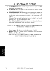
... you update your BIOS or download a BIOS image file. • PC-cillin 2000 Vx.xx: Installs the PC-cillin virus protection software. S/W SETUP Windows 98 76 ASUS CUSI-FX User's Manual SOFTWARE SETUP • Install ASUS Update Vx.xx: Installs a program to help for more information. • Adobe Acrobat Reader Vx.x: Installs the Adobe Acrobat Reader software necessary to view the support CD file list and contact information. • Exit: Exits the CD installation menu. (TO...
... you update your BIOS or download a BIOS image file. • PC-cillin 2000 Vx.xx: Installs the PC-cillin virus protection software. S/W SETUP Windows 98 76 ASUS CUSI-FX User's Manual SOFTWARE SETUP • Install ASUS Update Vx.xx: Installs a program to help for more information. • Adobe Acrobat Reader Vx.x: Installs the Adobe Acrobat Reader software necessary to view the support CD file list and contact information. • Exit: Exits the CD installation menu. (TO...

CUSI-FX User Manual
Page 90
... will start VideoLive Mail, click the Windows Start button, point to enter your ISP or MIS staff for VLM 3, if there are not sure. Then the Video Configuration screen shows up. The Internet e-mail configuration screen appears. Note that you through configuring the video and audio input peripherals and to configure the hardware and E-mail setting. S/W REFERENCE Windows 98 6. SOFTWARE REFERENCE 6.6.1 Starting VideoLive Mail To start and guide you want to setup the...
... will start VideoLive Mail, click the Windows Start button, point to enter your ISP or MIS staff for VLM 3, if there are not sure. Then the Video Configuration screen shows up. The Internet e-mail configuration screen appears. Note that you through configuring the video and audio input peripherals and to configure the hardware and E-mail setting. S/W REFERENCE Windows 98 6. SOFTWARE REFERENCE 6.6.1 Starting VideoLive Mail To start and guide you want to setup the...
CUSI-FX User Manual
Page 91
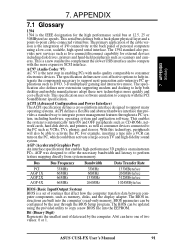
... for external devices including disk drives, printers and hand-held peripherals such as VCRs, TVs, phones, and stereos. BIOS parameters can be updated using a low-cost, scalable, high-speed serial interface. A bit can turn ON and OFF peripherals such as CD-ROMs, network cards, hard disk drives, and printers, as well as consumer devices connected to support next-generation auto-intensive PC applications such as memory, disks, and the display adapter. The BIOS can...
... for external devices including disk drives, printers and hand-held peripherals such as VCRs, TVs, phones, and stereos. BIOS parameters can be updated using a low-cost, scalable, high-speed serial interface. A bit can turn ON and OFF peripherals such as CD-ROMs, network cards, hard disk drives, and printers, as well as consumer devices connected to support next-generation auto-intensive PC applications such as memory, disks, and the display adapter. The BIOS can...

CUSI-FX User Manual
Page 93
... POST checks system memory, the motherboard circuitry, the display, the keyboard, the diskette drive, and other I /O address, DMA channels and interrupt levels among multiple ISA cards. This type of architecture transfers data through the POST, a series of software-controlled diagnostic tests. RDRAM (Rambus DRAM) Developed by each card's configuration, which is configured to system and device power control. 7. MMX A set of data per second. PCI Bus Master The PCI Bus Master...
... POST checks system memory, the motherboard circuitry, the display, the keyboard, the diskette drive, and other I /O address, DMA channels and interrupt levels among multiple ISA cards. This type of architecture transfers data through the POST, a series of software-controlled diagnostic tests. RDRAM (Rambus DRAM) Developed by each card's configuration, which is configured to system and device power control. 7. MMX A set of data per second. PCI Bus Master The PCI Bus Master...


