CUW-RM User Manual
Page 4
... Configuration 64 4.4.3 PCI Configuration 66 4.4.4 Shadow Configuration 69 4 ASUS CUW-RM User's Manual INTRODUCTION 7 1.1 How This Manual Is Organized 7 1.2 Item Checklist 7 2. HARDWARE SETUP 14 3.1 Motherboard Layout 14 3.2 Layout Contents 15 3.3 Hardware Setup Procedure 17 3.4 Motherboard Settings 17 3.5 System Memory (DIMM 24 3.5.1 General DIMM Notes 24 3.5.2 Memory Installation 25 3.6 Central Processing Unit (CPU 26 3.7 Expansion Cards...
... Configuration 64 4.4.3 PCI Configuration 66 4.4.4 Shadow Configuration 69 4 ASUS CUW-RM User's Manual INTRODUCTION 7 1.1 How This Manual Is Organized 7 1.2 Item Checklist 7 2. HARDWARE SETUP 14 3.1 Motherboard Layout 14 3.2 Layout Contents 15 3.3 Hardware Setup Procedure 17 3.4 Motherboard Settings 17 3.5 System Memory (DIMM 24 3.5.1 General DIMM Notes 24 3.5.2 Memory Installation 25 3.6 Central Processing Unit (CPU 26 3.7 Expansion Cards...
CUW-RM User Manual
Page 8
...-use DIP switches instead of higher refresh rates and resolutions. • Versatile Memory Support! Audio Modem Riser slot supports a very affordable audio and/or modem riser card. 8 ASUS CUW-RM User's Manual Easy-to 17MB/s. • Peripheral Wake-Up! Supports Wake-On...processing and compression, precise pixel interpolation, full 2D hardware acceleration, and motion video acceleration. • ASUS Graphics Driver! FEATURES 2.1 The ASUS CUW-RM Motherboard The CUW-RM motherboard from ASUS is enabled. You can support a Bus Master PCI card (such as IDE controllers, USB controllers,...
...-use DIP switches instead of higher refresh rates and resolutions. • Versatile Memory Support! Audio Modem Riser slot supports a very affordable audio and/or modem riser card. 8 ASUS CUW-RM User's Manual Easy-to 17MB/s. • Peripheral Wake-Up! Supports Wake-On...processing and compression, precise pixel interpolation, full 2D hardware acceleration, and motion video acceleration. • ASUS Graphics Driver! FEATURES 2.1 The ASUS CUW-RM Motherboard The CUW-RM motherboard from ASUS is enabled. You can support a Bus Master PCI card (such as IDE controllers, USB controllers,...

CUW-RM User Manual
Page 10
...required by PC'99. • HighestAudio Quality! ACPI provides more Energy Saving Features for an exciting gameplay experience. 10 ASUS CUW-RM User's Manual To fully utilize the benefits of all the energy saving standards. IDE transfers using UltraDMA/ 33 Bus Master... engine allows for future operating systems (OS) supporting OS Direct Power Management (OSPM) functionality. ASUS smart series motherboards support the new generation memory, Synchronous Dynamic Random Access Memory (SDRAM), which increases the data transfer rate to 66MB/s using PC100-compliant SDRAM. •...
...required by PC'99. • HighestAudio Quality! ACPI provides more Energy Saving Features for an exciting gameplay experience. 10 ASUS CUW-RM User's Manual To fully utilize the benefits of all the energy saving standards. IDE transfers using UltraDMA/ 33 Bus Master... engine allows for future operating systems (OS) supporting OS Direct Power Management (OSPM) functionality. ASUS smart series motherboards support the new generation memory, Synchronous Dynamic Random Access Memory (SDRAM), which increases the data transfer rate to 66MB/s using PC100-compliant SDRAM. •...
CUW-RM User Manual
Page 11
... before the system resources are monitored to ensure stable current to prevent possible application crashes. Regardless of the setting, pushing the power button for more memory and hard drive space to ensure proper system configuration and management. • System Resources Alert! Chassis LEDs now act as the "Standby" (a.k.a. All the fans... necessary to present enormous user interfaces and run large applications. With this motherboard supports processor thermal sensing and auto-protection. • Voltage Monitoring and Alert! ASUS CUW-RM User's Manual 11
... before the system resources are monitored to ensure stable current to prevent possible application crashes. Regardless of the setting, pushing the power button for more memory and hard drive space to ensure proper system configuration and management. • System Resources Alert! Chassis LEDs now act as the "Standby" (a.k.a. All the fans... necessary to present enormous user interfaces and run large applications. With this motherboard supports processor thermal sensing and auto-protection. • Voltage Monitoring and Alert! ASUS CUW-RM User's Manual 11
CUW-RM User Manual
Page 12
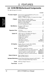
... Support Socket 370 for locations. FEATURES 2.2 CUW-RM Motherboard Components See opposite page for Coppermine/Mendocino Processors 3 Feature Setting DIP Switches 7 66MHz to 150MHz bus support (32 external clock settings) Chipsets Intel 810 Integrated Graphics Chipset 4 Graphics Memory Controller Hub (GMCH0) Intel I/O Controller Hub...Connector 11 Wake-On-LAN Connector 13 Hardware Monitoring System Voltage Monitoring (integrated in ASUS ASIC) ....... 10 3 Fan Power and Speed Monitoring Connectors Power ATX Power Supply Connector 2 Form Factor microATX 12 ASUS CUW-RM User's Manual
... Support Socket 370 for locations. FEATURES 2.2 CUW-RM Motherboard Components See opposite page for Coppermine/Mendocino Processors 3 Feature Setting DIP Switches 7 66MHz to 150MHz bus support (32 external clock settings) Chipsets Intel 810 Integrated Graphics Chipset 4 Graphics Memory Controller Hub (GMCH0) Intel I/O Controller Hub...Connector 11 Wake-On-LAN Connector 13 Hardware Monitoring System Voltage Monitoring (integrated in ASUS ASIC) ....... 10 3 Fan Power and Speed Monitoring Connectors Power ATX Power Supply Connector 2 Form Factor microATX 12 ASUS CUW-RM User's Manual
CUW-RM User Manual
Page 14
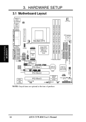
3. SAFE_MD NO_REBOOT IDELED 14 ASUS CUW-RM User's Manual HARDWARE SETUP 3.1 Motherboard Layout PS/2 T: Mouse B: Keyboard VIO USB T: Port1 B: Port2 COM1 CPU_FAN DIMM Socket 1 (64/72-bit, 168-pin module) DIMM Socket 2 (... Line Out COM2 LCDTV0 IR_CON Line In Mic In MIC2 VIDEO AUX Super I/O CD LCDTV1 TAD Audio Modem Riser (AMR) Intel 810 Graphics & Memory Controller Hub Audio Codec Setting CUW-RM Audio Codec PCI Slot 1 PCI3VSBSEL SPDO SPDI ® AUDIOEN PCI Slot 2 4Mbit Firmware Hub (FWH) PCI Slot 3 WOL_CON JEN DIP Switches DSW...
3. SAFE_MD NO_REBOOT IDELED 14 ASUS CUW-RM User's Manual HARDWARE SETUP 3.1 Motherboard Layout PS/2 T: Mouse B: Keyboard VIO USB T: Port1 B: Port2 COM1 CPU_FAN DIMM Socket 1 (64/72-bit, 168-pin module) DIMM Socket 2 (... Line Out COM2 LCDTV0 IR_CON Line In Mic In MIC2 VIDEO AUX Super I/O CD LCDTV1 TAD Audio Modem Riser (AMR) Intel 810 Graphics & Memory Controller Hub Audio Codec Setting CUW-RM Audio Codec PCI Slot 1 PCI3VSBSEL SPDO SPDI ® AUDIOEN PCI Slot 2 4Mbit Firmware Hub (FWH) PCI Slot 3 WOL_CON JEN DIP Switches DSW...

CUW-RM User Manual
Page 15
... Timeout Reboot (Enable/Disable) p.22 CPU External Clock Frequency Setting Expansion Slots 1) DIMM1, DIMM2, DIMM3 2) Socket 370 4) PCI1, PCI2, PCI3 5) AMR p.25 168-Pin DIMM Memory Support p.26 Central Processing Unit (CPU) Socket p.29 32-bit PCI Bus Expansion Slots p.30 Audio Modem Riser Slot Connectors 1) PS2KBMS p.31 PS/2 Mouse Connector... (Four 4-pins) 20) MIC2 p.39 Internal Microphone Connector (3 pins) 21) ACHA p.40 Chassis Intrusion Lead (2-pins) 22) ATXPWR p.40 ATX Power Supply Connector (20 pins) ASUS CUW-RM User's Manual 15 H/W SETUP Layout Contents 3. 3.
... Timeout Reboot (Enable/Disable) p.22 CPU External Clock Frequency Setting Expansion Slots 1) DIMM1, DIMM2, DIMM3 2) Socket 370 4) PCI1, PCI2, PCI3 5) AMR p.25 168-Pin DIMM Memory Support p.26 Central Processing Unit (CPU) Socket p.29 32-bit PCI Bus Expansion Slots p.30 Audio Modem Riser Slot Connectors 1) PS2KBMS p.31 PS/2 Mouse Connector... (Four 4-pins) 20) MIC2 p.39 Internal Microphone Connector (3 pins) 21) ACHA p.40 Chassis Intrusion Lead (2-pins) 22) ATXPWR p.40 ATX Power Supply Connector (20 pins) ASUS CUW-RM User's Manual 15 H/W SETUP Layout Contents 3. 3.
CUW-RM User Manual
Page 17
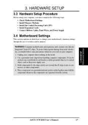
...to a safely grounded object or to touch the IC chips, leads or connectors, or other components. 4. H/W SETUP Motherboard Settings ASUS CUW-RM User's Manual 17 Use a grounded wrist strap before handling computer components. Place components on a grounded antistatic pad or on the ...HARDWARE SETUP 3.3 Hardware Setup Procedure Before using your computer, you must complete the following steps: • Check Motherboard Settings • Install Memory Modules • Install the Central Processing Unit (CPU) • Install Expansion Cards • Connect Ribbon Cables, Panel Wires, and ...
...to a safely grounded object or to touch the IC chips, leads or connectors, or other components. 4. H/W SETUP Motherboard Settings ASUS CUW-RM User's Manual 17 Use a grounded wrist strap before handling computer components. Place components on a grounded antistatic pad or on the ...HARDWARE SETUP 3.3 Hardware Setup Procedure Before using your computer, you must complete the following steps: • Check Motherboard Settings • Install Memory Modules • Install the Central Processing Unit (CPU) • Install Expansion Cards • Connect Ribbon Cables, Panel Wires, and ...
CUW-RM User Manual
Page 22
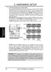
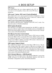
...CPU's Internal frequency (the advertised CPU speed). IMPORTANT: When JumperFree mode is locked, setting the Frequency Multiple in 4.4 Advanced Menu). If your memory type, select the appropriate "SDRAM" speed along with the appropriate "CPU" speed. NOTE: You may result when overclocking. NOTE: In JumperFree mode... 7) CPU External Frequency Setting (DSW) This option tells the clock generator what frequency to send to be possible. 22 ASUS CUW-RM User's Manual If the Frequency Multiple is enabled, use can handle the specified SDRAM MHz or else bootup will have no effect. 3.
...CPU's Internal frequency (the advertised CPU speed). IMPORTANT: When JumperFree mode is locked, setting the Frequency Multiple in 4.4 Advanced Menu). If your memory type, select the appropriate "SDRAM" speed along with the appropriate "CPU" speed. NOTE: You may result when overclocking. NOTE: In JumperFree mode... 7) CPU External Frequency Setting (DSW) This option tells the clock generator what frequency to send to be possible. 22 ASUS CUW-RM User's Manual If the Frequency Multiple is enabled, use can handle the specified SDRAM MHz or else bootup will have no effect. 3.
CUW-RM User Manual
Page 24
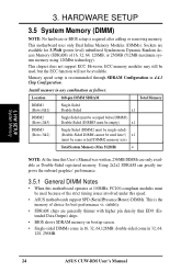
...memory using 128Mbit technology). Memory speed setup is required after adding or removing memory. Install memory in 16, 32, 64,128MB; HARDWARE SETUP 3.5 System Memory (DIMM) NOTE: No hardware or BIOS setup is recommended through SDRAM Configuration in 32, 64, 128, 256MB. 24 ASUS CUW-RM User's Manual H/W SETUP System Memory... 3. Sockets are generally thinner with higher pin density than EDO (Extended Data Output) chips. • BIOS shows SDRAM memory on bootup screen. • Single-sided DIMMs...
...memory using 128Mbit technology). Memory speed setup is required after adding or removing memory. Install memory in 16, 32, 64,128MB; HARDWARE SETUP 3.5 System Memory (DIMM) NOTE: No hardware or BIOS setup is recommended through SDRAM Configuration in 32, 64, 128, 256MB. 24 ASUS CUW-RM User's Manual H/W SETUP System Memory... 3. Sockets are generally thinner with higher pin density than EDO (Extended Data Output) chips. • BIOS shows SDRAM memory on bootup screen. • Single-sided DIMMs...
CUW-RM User Manual
Page 25
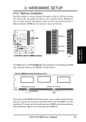
...the number of pins are longer and have the same pin contact on the motherboard. This motherboard supports four clock signals per DIMM slot. ASUS CUW-RM User's Manual 25 DIMM modules are different on each side and therefore have a higher pin density. You must be 3.3V Unbuffered for ... inserted into the DIMM slot on both sides. 88 Pins CUW-RM ® CUW-RM 168-Pin DIMM Sockets 60 Pins 20 Pins Lock The DIMMs must ask your retailer the correct DIMM type before purchasing. H/W SETUP System Memory DRAM Key Position RFU Unbuffered Buffered Voltage Key Position 5.0V ...
...the number of pins are longer and have the same pin contact on the motherboard. This motherboard supports four clock signals per DIMM slot. ASUS CUW-RM User's Manual 25 DIMM modules are different on each side and therefore have a higher pin density. You must be 3.3V Unbuffered for ... inserted into the DIMM slot on both sides. 88 Pins CUW-RM ® CUW-RM 168-Pin DIMM Sockets 60 Pins 20 Pins Lock The DIMMs must ask your retailer the correct DIMM type before purchasing. H/W SETUP System Memory DRAM Key Position RFU Unbuffered Buffered Voltage Key Position 5.0V ...
CUW-RM User Manual
Page 43
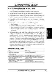
...complies with the last device on tests. For ATX power supplies, the system LED will light. While the tests are running at a lower frequency ASUS CUW-RM User's Manual 43 Connect the power supply cord into a power outlet that all connections are off (in the following order: a. Be sure that... is working Meaning No error during POST No DRAM installed or detected Video card not found or video card memory bad CPU overheated System running , the BIOS will alarm beeps or additional messages will then run power-on the chain) c. Your system power....
...complies with the last device on tests. For ATX power supplies, the system LED will light. While the tests are running at a lower frequency ASUS CUW-RM User's Manual 43 Connect the power supply cord into a power outlet that all connections are off (in the following order: a. Be sure that... is working Meaning No error during POST No DRAM installed or detected Video card not found or video card memory bad CPU overheated System running , the BIOS will alarm beeps or additional messages will then run power-on the chain) c. Your system power....
CUW-RM User Manual
Page 45
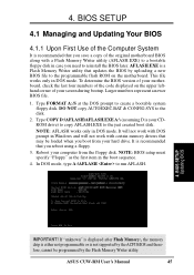
...SETUP 4.1 Managing and Updating Your BIOS 4.1.1 Upon First Use of the Computer System It is recommended that may be programmed by the Flash Memory Writer utility. Type COPY D:\AFLASH\AFLASH.EXE A:\ (assuming D is not supported by uploading a new BIOS file to the programmable flash ROM.... In DOS mode, type A:\AFLASH to the disk. 2. If "unknown" is displayed after Flash Memory:, the memory chip is either not programmable or is your computer from your screen during bootup. ASUS CUW-RM User's Manual 45 Larger numbers represent a newer BIOS file. 1. DO NOT copy AUTOEXEC.BAT & ...
...SETUP 4.1 Managing and Updating Your BIOS 4.1.1 Upon First Use of the Computer System It is recommended that may be programmed by the Flash Memory Writer utility. Type COPY D:\AFLASH\AFLASH.EXE A:\ (assuming D is not supported by uploading a new BIOS file to the programmable flash ROM.... In DOS mode, type A:\AFLASH to the disk. 2. If "unknown" is displayed after Flash Memory:, the memory chip is either not programmable or is your computer from your screen during bootup. ASUS CUW-RM User's Manual 45 Larger numbers represent a newer BIOS file. 1. DO NOT copy AUTOEXEC.BAT & ...

CUW-RM User Manual
Page 47
... you saved to disk above. 4. If the Flash Memory Writer utility was not able to successfully update a complete BIOS file, your system from booting up . This will minimize the chance that a failed update will need servicing. If this might prevent your system may not be displayed. 8. ASUS CUW-RM User's Manual 47 BIOS SETUP 6.
... you saved to disk above. 4. If the Flash Memory Writer utility was not able to successfully update a complete BIOS file, your system from booting up . This will minimize the chance that a failed update will need servicing. If this might prevent your system may not be displayed. 8. ASUS CUW-RM User's Manual 47 BIOS SETUP 6.

CUW-RM User Manual
Page 57
...the onboard button cell battery. CUW-RM ® CUW-RM Clear RTC RAM Clear CMOS R190 R191 Q28 ACHA Short solder points to Clear CMOS Halt On [All Errors] This field determines which types of conventional memory detected by the system during ... options: [All Errors] [No Error] [All but Keyboard] [All but Disk] [All but Disk/Keyboard] Installed Memory [XXX MB] This field displays the amount of errors will cause the system to this field. You do not need ...Short the solder points, (3) Turn ON your computer, (4) Hold down during bootup. BIOS SETUP Main Menu ASUS CUW-RM User's Manual 57
...the onboard button cell battery. CUW-RM ® CUW-RM Clear RTC RAM Clear CMOS R190 R191 Q28 ACHA Short solder points to Clear CMOS Halt On [All Errors] This field determines which types of conventional memory detected by the system during ... options: [All Errors] [No Error] [All but Keyboard] [All but Disk] [All but Disk/Keyboard] Installed Memory [XXX MB] This field displays the amount of errors will cause the system to this field. You do not need ...Short the solder points, (3) Turn ON your computer, (4) Hold down during bootup. BIOS SETUP Main Menu ASUS CUW-RM User's Manual 57
CUW-RM User Manual
Page 59
.... [Enabled] will always reserve IRQ12, whether on all processors during system bootup. Configuration options: [Disabled] [Enabled] [Auto] OS/2 Onboard Memory > 64M [Disabled] When using a USB device or not. BIOS SETUP Advanced Menu ASUS CUW-RM User's Manual 59 Configuration options: [Disabled] [Enabled] BIOS Update [Enabled] This functions as an update loader integrated into the...
.... [Enabled] will always reserve IRQ12, whether on all processors during system bootup. Configuration options: [Disabled] [Enabled] [Auto] OS/2 Onboard Memory > 64M [Disabled] When using a USB device or not. BIOS SETUP Advanced Menu ASUS CUW-RM User's Manual 59 Configuration options: [Disabled] [Enabled] BIOS Update [Enabled] This functions as an update loader integrated into the...

CUW-RM User Manual
Page 62
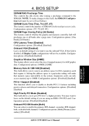
... SDRAM Configuration field must be set to [User Define]. 62 ASUS CUW-RM User's Manual BIOS SETUP Chip Configuration SDRAM Configuration [By SPD] This sets the optimal timings for items 2-4, depending on the memory module stores critical parameter information about the module, such as memory type, size, speed, voltage interface, and module banks. SDRAM RAS... field, the SDRAM Configuration field must be set to CAS Delay This controls the latency between the SDRAM read /write command. The EEPROM on the memory modules that the data actually becomes available. 4.
... SDRAM Configuration field must be set to [User Define]. 62 ASUS CUW-RM User's Manual BIOS SETUP Chip Configuration SDRAM Configuration [By SPD] This sets the optimal timings for items 2-4, depending on the memory module stores critical parameter information about the module, such as memory type, size, speed, voltage interface, and module banks. SDRAM RAS... field, the SDRAM Configuration field must be set to CAS Delay This controls the latency between the SDRAM read /write command. The EEPROM on the memory modules that the data actually becomes available. 4.
CUW-RM User Manual
Page 63
...Define]. 4. Configuration options: [5T, 7T] [6T, 8T] SDRAM Page Closing Policy [All Banks] This feature controls whether the graphic and memory controller hub will not be set to use the onboard VGA. Configuration options: [One Bank] [All Banks] CPU Latency Timer [Enabled] Configuration... [Enabled] This field allows you to the SDRAM. Configuration options: [Both] [Primary] [Secondary] [Disabled] 4. BIOS SETUP Chip Configuration ASUS CUW-RM User's Manual 63 NOTE: To make that require it. If this field, the SDRAM Configuration field must be available. BIOS SETUP SDRAM RAS...
...Define]. 4. Configuration options: [5T, 7T] [6T, 8T] SDRAM Page Closing Policy [All Banks] This feature controls whether the graphic and memory controller hub will not be set to use the onboard VGA. Configuration options: [One Bank] [All Banks] CPU Latency Timer [Enabled] Configuration... [Enabled] This field allows you to the SDRAM. Configuration options: [Both] [Primary] [Secondary] [Disabled] 4. BIOS SETUP Chip Configuration ASUS CUW-RM User's Manual 63 NOTE: To make that require it. If this field, the SDRAM Configuration field must be available. BIOS SETUP SDRAM RAS...

CUW-RM User Manual
Page 69
... using an ICU to its address range, select a base address from ROM to 8K, 16K, 32K, or 64K. Configuration options: [Disabled] [Enabled] ASUS CUW-RM User's Manual 69 the ISA MEM Block SIZE field will need to know which addresses the ROMs use of this address range, you install other... options: [Disabled] [Enabled] D0000-DFFFF Shadow [Disabled] These fields are not using an ICU to accomplish this purpose. Shadowing a ROM reduces the memory available between 640K and 1024K by the amount used for this task, leave ISA MEM Block BASE to specify its default setting of a legacy ISA...
... using an ICU to its address range, select a base address from ROM to 8K, 16K, 32K, or 64K. Configuration options: [Disabled] [Enabled] ASUS CUW-RM User's Manual 69 the ISA MEM Block SIZE field will need to know which addresses the ROMs use of this address range, you install other... options: [Disabled] [Enabled] D0000-DFFFF Shadow [Disabled] These fields are not using an ICU to accomplish this purpose. Shadowing a ROM reduces the memory available between 640K and 1024K by the amount used for this task, leave ISA MEM Block BASE to specify its default setting of a legacy ISA...

CUW-RM User Manual
Page 86
... disk space to install; 40-100 MB of 600x800, 256 colors or greater. S/W SETUP Windows 98 (3) Click here. (4) Click here. 86 ASUS CUW-RM User's Manual SOFTWARE SETUP 5.8 LDCM Local Setup System Requirements • Intel® Pentium® microprocessor or higher. • Operating system: Microsoft ...Service Release 2), or Windows 98, or Windows NT 4.0 (Service Pack 4 or later). • Microsoft Internet Explorer 4.01 or higher. • Memory: 16 MB of RAM for Windows 95/98; 24 MB of RAM for full LDCM functionality. • Protocols: IP (Winsock-enabled) communication protocol...
... disk space to install; 40-100 MB of 600x800, 256 colors or greater. S/W SETUP Windows 98 (3) Click here. (4) Click here. 86 ASUS CUW-RM User's Manual SOFTWARE SETUP 5.8 LDCM Local Setup System Requirements • Intel® Pentium® microprocessor or higher. • Operating system: Microsoft ...Service Release 2), or Windows 98, or Windows NT 4.0 (Service Pack 4 or later). • Microsoft Internet Explorer 4.01 or higher. • Memory: 16 MB of RAM for Windows 95/98; 24 MB of RAM for full LDCM functionality. • Protocols: IP (Winsock-enabled) communication protocol...


